<?xml version="1.0" encoding="UTF-8"?>
<feed xmlns="http://www.w3.org/2005/Atom" xml:lang="en-US">
                        <id>https://convergecfd.com/blog-feed</id>
                                <link href="https://convergecfd.com/blog-feed" rel="self"></link>
                                <title><![CDATA[Convergent Science Blog Feed]]></title>
                    
                                <subtitle></subtitle>
                                                    <updated>2026-04-23T09:38:07+00:00</updated>
                        <entry>
            <title><![CDATA[Effects of the CREST Slip-Wall Model and Higher-Order Continuum Momentum Corrections on Local Non-Equilibrium Flow]]></title>
            <link rel="alternate" href="https://convergecfd.com/blog/effects-of-the-crest-slip-wall-model-and-higher-order-continuum-momentum-corrections-on-local-non-equilibrium-flow" />
            <id>https://convergecfd.com/250</id>
            <author>
                <name><![CDATA[Convergent Science]]></name>
            </author>
            <summary type="html">
                <![CDATA[
<div id="attachment_4079" class=" wp-caption  alignright" style="width: 160px;">
  <img loading="lazy" decoding="async" class="size-thumbnail" src="https://convergecfd.canto.com/direct/image/pec4a457a17779p4jc9vifu74l/8yt0xLwg3V-35NVMqkn9I2lWNM4/original?content-type=image%2Fpng&#038;name=Jay_headshot.png" width="150" height="150">
  <p style="margin-bottom: -0.5%"><span class="bold">Author:<br>Junhyeong (Jay) Ahn</span></p>
  <p><span style="text-transform: none;">Mechanical Engineering Graduate Student</span></p>
  <p><span style="text-transform: none;">PennState University Harrisburg</span></p>
</div>


<p>As aerospace engineering advances, researchers continue to explore flight at higher speeds and over greater distances than ever before. These developments require new technologies and innovative strategies for designing and testing advanced vehicles. Consequently, high-fidelity numerical simulation has emerged as a central tool in aerospace research. Engineers routinely use computational fluid dynamics (CFD) to evaluate new concepts, identify critical design flaws, and improve performance before costly experiments or flight tests. Yet, in focusing on simulation capability, we sometimes overlook the underlying foundation that makes these analyses possible: the governing equations themselves.</p>


<p>Fluid-flow simulations generally follow one of two approaches: molecular-based modeling or continuum-based modeling.<sup>1</sup> Molecular approaches, such as Direct Simulation Monte Carlo (DSMC) and Boltzmann-based kinetic solvers, are well known in the aerospace community and can accurately represent non-equilibrium effects. However, these methods are computationally expensive and mathematically more difficult to handle than conventional continuum models. For this reason, continuum-based CFD remains the preferred approach whenever the continuum assumption is valid, that is, when the flow remains sufficiently close to local thermodynamic equilibrium. Nevertheless, many challenging flows exhibit strong local non-equilibrium effects, particularly in high-speed and rarefied regimes, where the conventional continuum governing equations may no longer yield accurate predictions.<sup>2</sup> In such cases, maintaining accuracy within a continuum framework requires modified boundary conditions and, when necessary, adding higher-order continuum corrections to the governing equations, especially in the momentum and energy transport equations.</p>


<figure class="wp-block-image size-large"><img decoding="async" src="https://convergecfd.canto.com/direct/image/2r1pre9n9p6qt29927nb4puq6c/yp7NcWxfPwzRR6qNw42SXiJUoT8/original?content-type=image%2Fpng&amp;name=Figure_1_FIxed_Heirarchy.png" alt=""/><figcaption class="wp-element-caption">Figure 1: Schematic comparison of molecular and continuum modeling approaches.</figcaption></figure>


<h3 class="wp-block-heading"><strong>Slip-Flow Regime </strong>(0.001 &lt; Kn &lt; 0.1)</h3>


<p>When the Knudsen number, Kn, lies between 0.001 and 0.1, the flow is generally classified as being in the slip-flow regime.<sup>1</sup> In this range, rarefaction effects become important, and the classical no-slip boundary condition is no longer strictly valid. Although the bulk flow may still be described within a continuum framework, the wall boundary conditions must be modified to preserve accuracy of the continuum model.</p>


<p>The most widely used correction is the Maxwell slip boundary condition, which is derived from kinetic theory. This treatment provides a physically motivated wall-slip velocity and improves prediction accuracy in rarefied flows. However, numerical implementation of the Maxwell slip model can introduce strong cell-to-cell velocity variations in the near-wall region. These sharp variations become particularly problematic when higher-order continuum correction terms are added, because the solver then becomes more sensitive to local gradient oscillations and may exhibit unstable behavior.</p>


<p>To address this issue, I proposed a more dissipative and numerically stable slip-wall treatment, CREST (Continuum-Rarefied Explicit Slip Treatment). Compared with the conventional Maxwell slip treatment, CREST produces smoother near-wall velocity variations from cell to cell while still preserving slip effects. This smoothing improves numerical stability when higher-order continuum correction terms are included. At the same time, CREST retains accuracy close to that of the Maxwell slip model.</p>


<p>
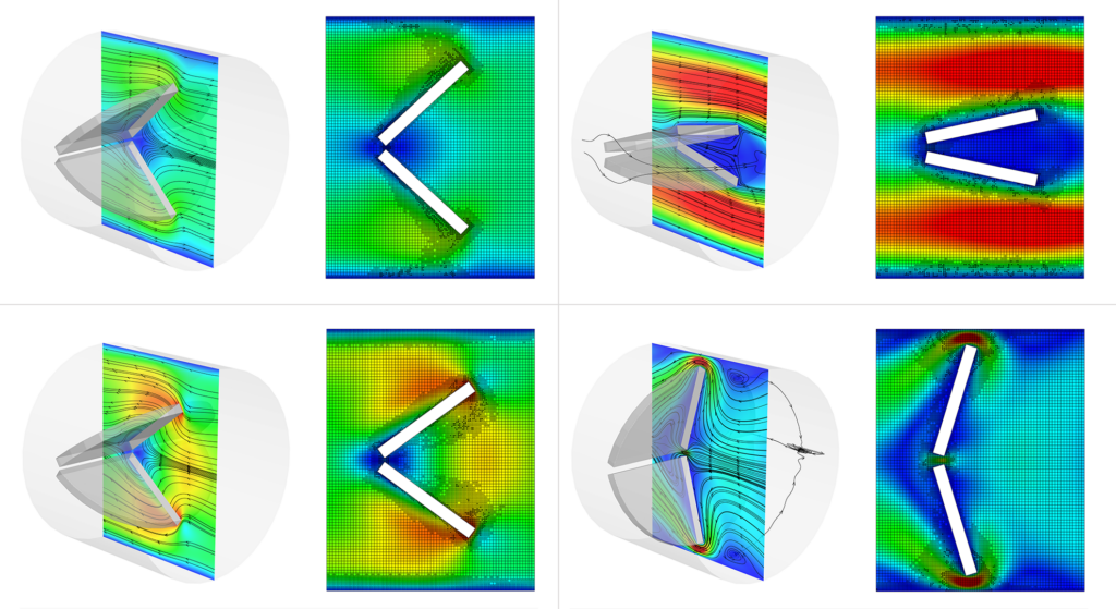
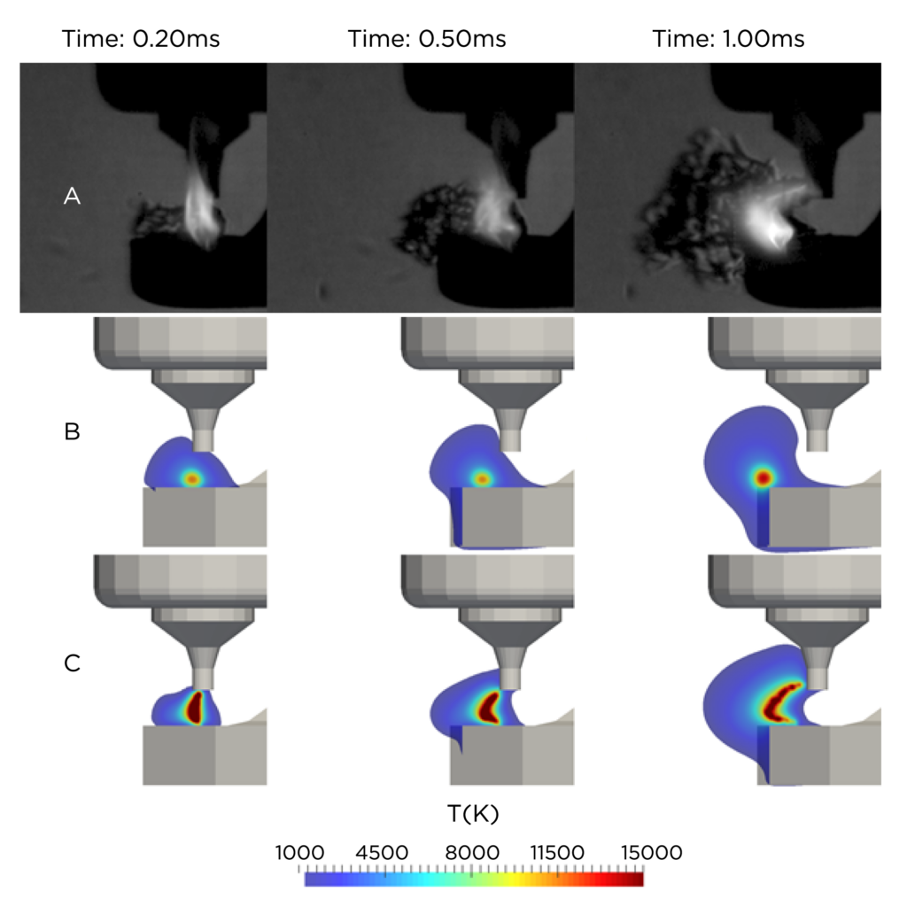
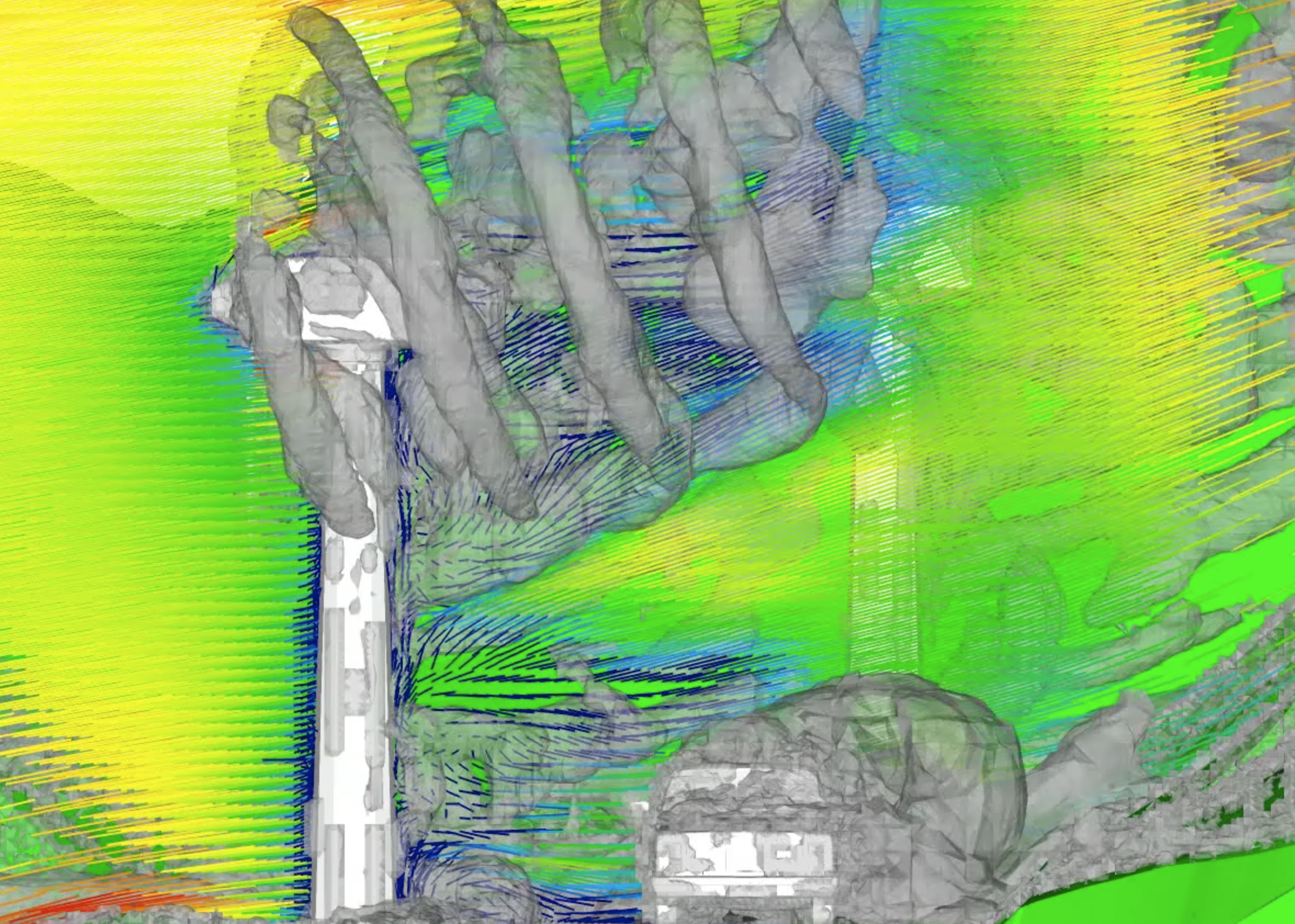
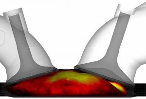
Figure 2 illustrates this behavior for the double-cone flow problem, a benchmark configuration introduced in 2001 for hypersonic code validation.<sup>3</sup> The left panel shows the solution obtained with a no-slip wall boundary condition, the middle panel shows the result with the Maxwell slip treatment, and the right panel shows the result with the CREST slip treatment. The no-slip solution, which assumes continuum behavior at the wall, overpredicts the separation zone generated by shock-shock interactions. In contrast, both the Maxwell and CREST slip treatments predict separation-zone sizes much more accurately.</p>


<figure class="wp-block-image size-large"><img decoding="async" src="https://convergecfd.canto.com/direct/image/8ks5j74q6h48jco9pqhcb86q1d/NNYQnARXI1EYQTgxDx1whlSyE_g/original?content-type=image%2Fpng&amp;name=Figure_2_Density_Combined.png" alt=""/><figcaption class="wp-element-caption">Figure 2: Comparison of density contours in double-cone flow using no-slip, Maxwell slip, and CREST slip models.</figcaption></figure>


<p>
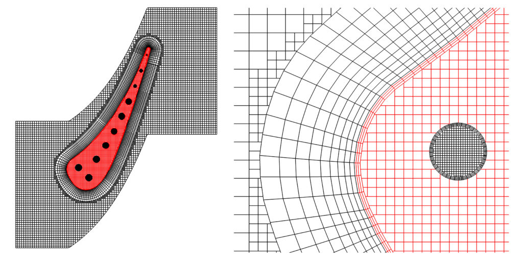
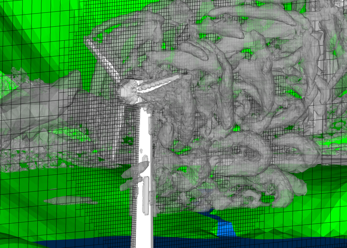
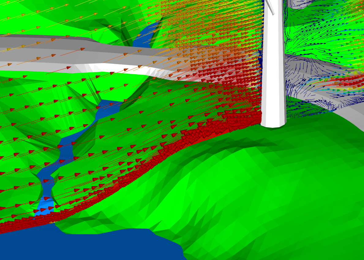
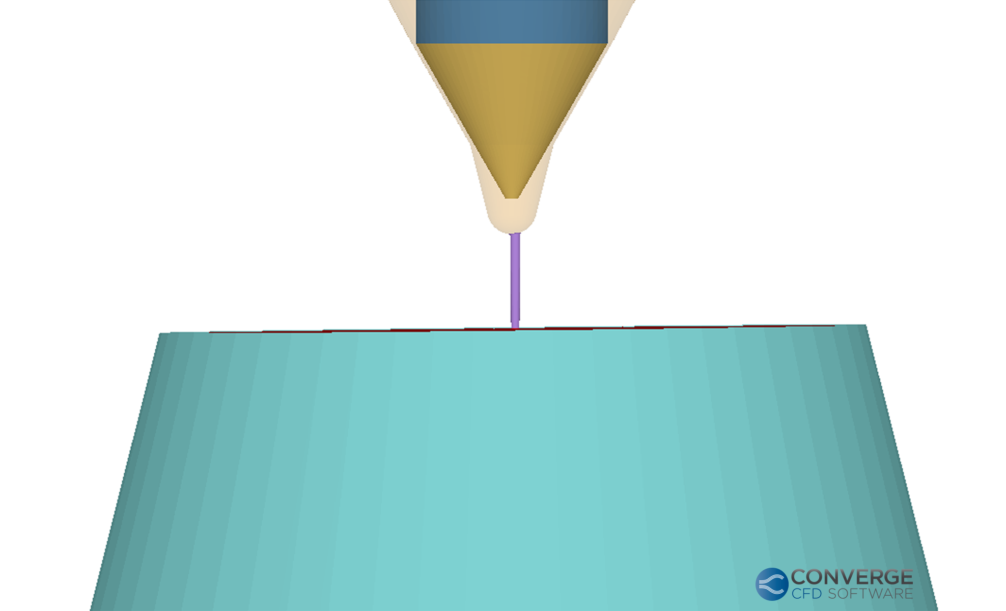
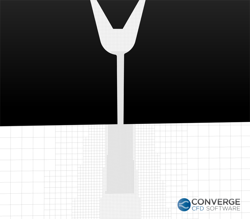
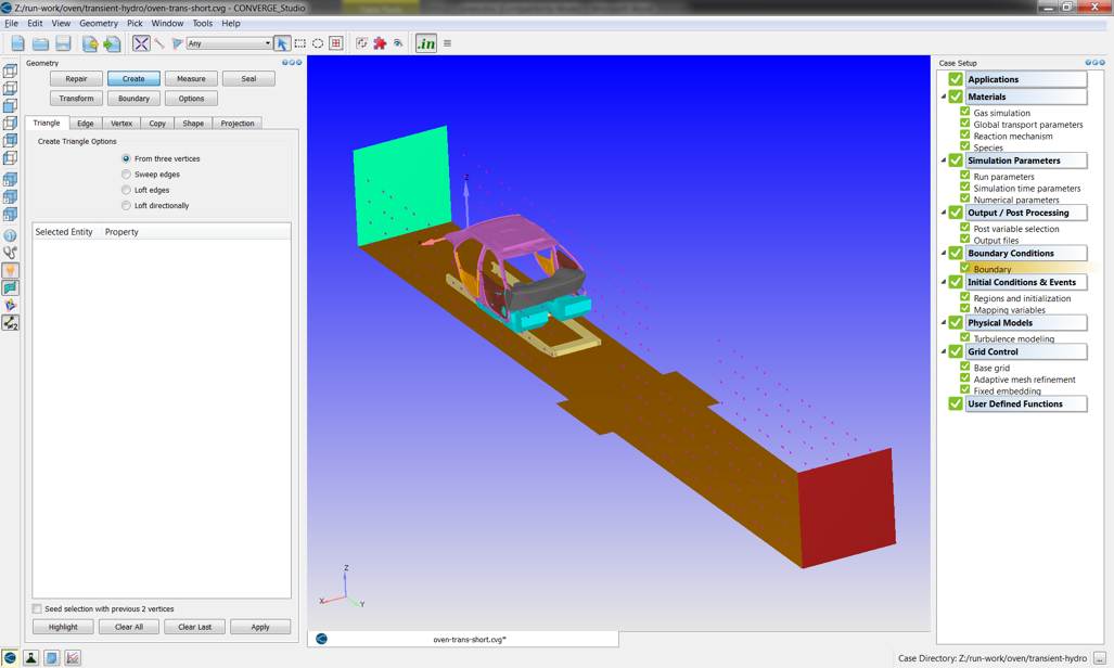
We implemented the CREST model in CONVERGE CFD software as a user-defined function (UDF). For the double-cone simulations, we employed a hybrid meshing strategy that combines CONVERGE’s automated Cartesian cut-cell approach with inlaid meshes generated in CONVERGE Studio. This strategy is particularly advantageous for compressible-flow simulations because it improves meshing efficiency while allowing greater focus on the underlying flow physics, such as wall momentum transport. In principle, the most accurate mesh for high-speed compressible flow would align shock waves with mesh faces, since shocks represent flow discontinuities. In practice, however, this is difficult to achieve within a structured-grid framework. CONVERGE’s automated Cartesian cut-cell method, together with localized mesh refinement in shock regions, therefore provides a practical and effective alternative that improves solution accuracy without requiring excessive meshing effort.</p>


<p>As shown in the results, the no-slip boundary condition overpredicts the separation region, indicating an overestimation of momentum diffusion in the momentum transport. In contrast, both the Maxwell-slip and CREST boundary conditions provide a more accurate representation of momentum diffusion and yield predictions that better match the experimental behavior.</p>


<h3 class="wp-block-heading"><strong>Transitional-Flow Regime</strong> (0.1 &lt; Kn &lt; 10)</h3>


<p>When the Knudsen number lies between 0.1 and 10, the flow is generally classified as being in the transitional regime.<sup>1</sup> In this range, rarefaction effects become substantially stronger than in the slip-flow regime, and modifying the wall boundary condition alone is no longer sufficient. To maintain accuracy within a continuum framework, higher-order continuum correction terms must be introduced into the governing equations. As the flow becomes more rarefied, local non-equilibrium effects grow more pronounced. From the perspective of momentum transport, these effects must be represented through the viscous stress tensor, since it is the term that carries the non-equilibrium contribution beyond the isotropic pressure. Consequently, the conventional Navier-Stokes viscous-stress closure must be extended. One systematic way to obtain this extension is through the Chapman-Enskog expansion of the Boltzmann equation, which yields the Burnett viscous-stress closure.<sup>2</sup></p>


<p>However, directly incorporating the Burnett viscous-stress closure into the momentum equation introduces well-known stability problems, particularly from the perspective of linear stability theory. To address this issue while retaining Burnett-level accuracy, the augmented Burnett formulation was introduced. Although this formulation improves the short-wavelength stability behavior, it also introduces third-order spatial derivatives into the viscous-stress closure, which produce fourth-order velocity derivatives when substituted into the momentum transport equation. The expanded form of the viscous-stress closure used in the momentum equation is shown below. Here, ω<sub>1</sub> through ω<sub>7</sub> denote coefficients determined by the selected molecular model. In the present study, the Maxwell molecular model is employed.</p>


<figure class="wp-block-image size-large"><img decoding="async" src="https://convergecfd.canto.com/direct/image/pm2jo54o9h7fp3fcbbufoiq70o/ZeMknn8ze-NNwmUKkVgzlwW_uAA/original?content-type=image%2Fpng&amp;name=Equation.png" alt=""/></figure>


<p>
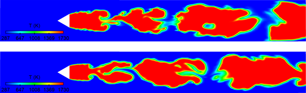
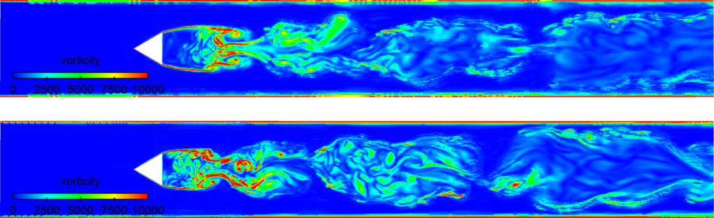
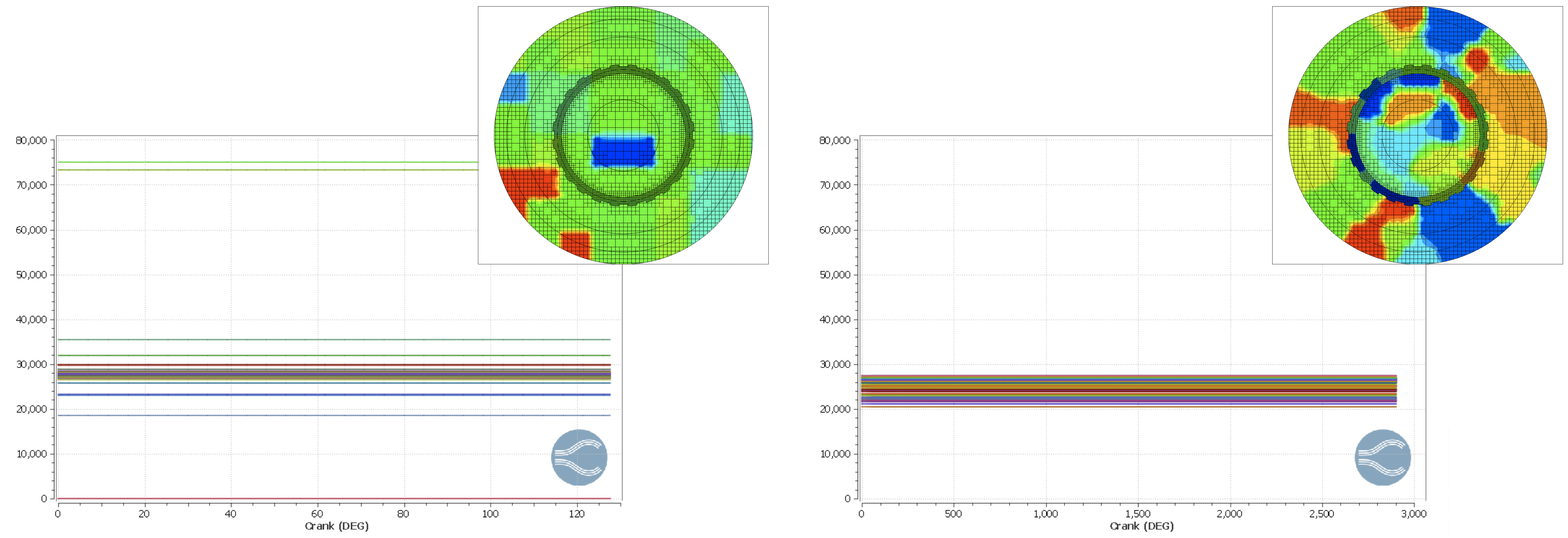
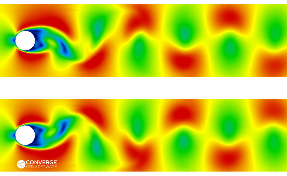
These higher-order derivatives make the numerical solution much more sensitive to cell-to-cell variations and local oscillations, which can in turn destabilize the solver. To overcome this difficulty, I developed a filtering algorithm with a shock sensor that selectively filters only the augmented Burnett term. Implemented in CONVERGE through a UDF, this approach preserves the accuracy associated with the Burnett viscous-stress closure while improving numerical stability. Figure 3 illustrates the effect of the filtering procedure relative to the raw (unfiltered) augmented Burnett viscous-stress closure. The filter effectively suppresses regions of strong cell-to-cell variation, thereby reducing numerical oscillation errors and preventing distortion of the shock curvature.</p>


<figure class="wp-block-image size-large"><img decoding="async" src="https://convergecfd.canto.com/direct/image/u6h6dt6rop7j1c55lspshikr1a/l-RuFH70NlezkyvHT85zmd8QCLA/original?content-type=image%2Fpng&amp;name=Figure_3_Filtration_Raw.png" alt=""/><figcaption class="wp-element-caption">Figure 3: Effect of filtration algorithm on augmented Burnett viscous-stress and resulting Mach contour.</figcaption></figure>


<p>
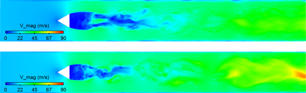
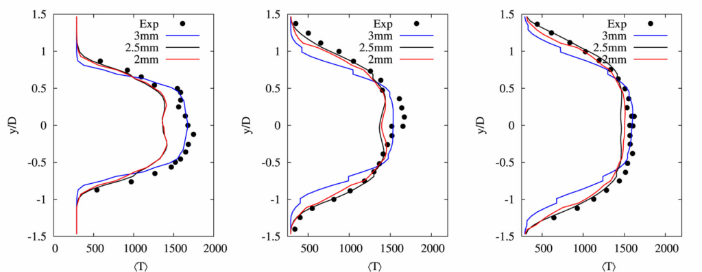
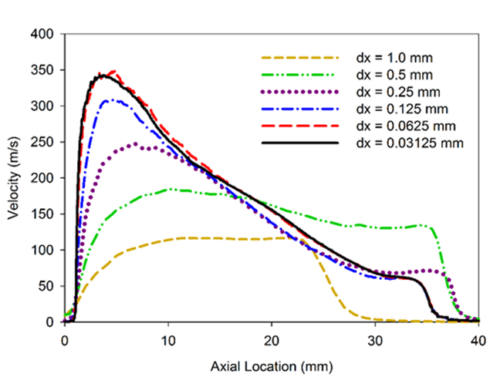
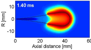
Figure 4 demonstrates the influence of the higher-order continuum correction terms on the solution. Velocity is plotted against reference distance to clearly compare the effects of the high-order continuum corrections. Temperature and Mach number contours are also presented using the same reference-distance framework. The top contour represents the Navier-Stokes viscous-closure solution, while the bottom contours represent the filtered augmented Burnett viscous-closure solution.</p>


<figure class="wp-block-image size-large"><img decoding="async" src="https://convergecfd.canto.com/direct/image/a721t1o9ep1gh74uq2d102kd07/acg5x3sfB0r2j6oFgfLV4N26Vug/original?content-type=image%2Fpng&amp;name=Figure_4_Augmented_Burnett_Vel.png" alt=""/><figcaption class="wp-element-caption">Figure 4: Filtered augmented Burnett and Navier-Stokes solution comparison based on velocity, temperature, and Mach contours.</figcaption></figure>


<p>For this two-dimensional flow over the cylinder, we employed a fully inlaid mesh generated in CONVERGE Studio. As shown in Figures 3 and 4, the inclusion of higher-order continuum correction terms produces noticeable differences in the computed solution, which may be critical in the analysis of hypersonic vehicles.</p>


<h3 class="wp-block-heading">Conclusion</h3>


<p>As discussed throughout this article, numerical methods, particularly continuum-based frameworks, play a central role in the design and analysis of advanced aerospace vehicles. These methods allow engineers to accurately evaluate innovative concepts and to accelerate the development process. However, their successful application depends on recognizing the assumptions that underlie the governing equations. When the flow exhibits stronger non-equilibrium effects, the conventional continuum equations, if used without correction, can produce inaccurate predictions and potentially lead to serious design errors that affect engineering decisions.</p>


<p>For this reason, it is essential to account for non-equilibrium effects when extending continuum CFD to rarefied-flow conditions. In the slip-flow regime, this requires modification of the wall boundary conditions. In more rarefied transitional regimes, boundary-condition corrections alone are not sufficient, and higher-order continuum correction terms must also be incorporated into the governing equations. Therefore, accurate and stable prediction of non-equilibrium flows requires both physically appropriate boundary treatments and carefully implemented higher-order continuum models.</p>


<h3 class="wp-block-heading">Supported by the CONVERGE Academic Program</h3>


<p>This work was performed as part of the CONVERGE Academic Program, which provides free licenses, training, and support for academic research. For this project, Jay collaborated directly with the CONVERGE Development team:</p>


<blockquote style="width: 85%; margin-left: 5%; margin-top: 2%; margin-bottom: 2%;">
    <i>“Our collaboration began through CONVERGE&#8217;s code-capability testing for hypersonic flow. From that point, I
    developed the idea of building our in-house slip-wall treatment, CREST, and I discussed the implementation with Dr.
    Chai [Solver Development Team Lead]. He helped guide me toward the correct implementation path within CONVERGE,
    especially in terms of which UDF APIs needed to be used and modified. The same was true for the 2D flow over the
    cylinder. I presented the new idea, and he helped direct me toward the appropriate implementation approach in
    CONVERGE.”</i>
</blockquote>


<p>The CONVERGE Academic Program enables students, professors, and academic researchers around the world to conduct high-impact CFD research. Learn more about the benefits and how to participate <a href="https://convergecfd.com/products/converge-academic-program">on our webpage</a>!</p>


<h3 class="wp-block-heading">References</h3>


<p>[1] Gad-el-Hak, M., “The Fluid Mechanics of Microdevices—The Freeman Scholar Lecture,” <em>Journal of Fluids Engineering</em>, 121(1), 5-33, 1999. DOI: 10.1115/1.2822013</p>


<p>[2] Cercignani, C. (Author) and Michaelis, C. (Reviewer), “Rarefied Gas Dynamics: From Basic Concepts to Actual Calculations. Cambridge Texts in Applied Mathematics,” <em>Applied Mechanics Reviews</em>, 54(5), B90-B92, 2001. DOI: 10.1115/1.1399679</p>


<p>[3] Holden, M., “Experimental Studies of Laminar Separated Flows Induced by Shock Wave/Boundary Layer and Shock/Shock Interaction in Hypersonic Flows for CFD Validation,” <em>38th Aerospace Sciences Meeting and Exhibit</em>, Reno, NV, United States, Jan 10-13, 2000. DOI: 10.2514/6.2000-930</p>
]]>
            </summary>
                                    <updated>2026-04-23T09:38:07+00:00</updated>
        </entry>
            <entry>
            <title><![CDATA[From Uncertainty to Confidence: Evaluating Flare Performance Using CONVERGE]]></title>
            <link rel="alternate" href="https://convergecfd.com/blog/from-uncertainty-to-confidence-evaluating-flare-performance-using-converge" />
            <id>https://convergecfd.com/249</id>
            <author>
                <name><![CDATA[Convergent Science]]></name>
            </author>
            <summary type="html">
                <![CDATA[
<div id="attachment_4079" class=" wp-caption  alignright" style="width: 160px;">
  <img loading="lazy" decoding="async" class="size-thumbnail" src="https://cdn.convergecfd.com/Gopal_S-1.jpg" width="150" height="150">
  <p style="margin-bottom: -0.5%"><span class="bold">Author:<br>Gopal S.</span></p>
  <p><span style="text-transform: none;">Engineer II &#8211; Marketing</span></p>
</div>


<p>If you&#8217;ve ever driven past an oil and gas facility, you&#8217;ve probably seen those large flames burning in the distance. Those are flares, and they’re doing something important: industrial facilities use them to burn excess natural gas that cannot be used economically. This process prevents the natural gas from escaping directly into the atmosphere, helping to safeguard the environment. However, if the combustion efficiency of the flares drops, methane—one of the most potent greenhouse gases—escapes unburned.</p>


<p>The key measure of flare performance is called the destruction and removal efficiency, or DRE, which indicates the percentage of harmful compounds a flare successfully eliminates through combustion. In general, DRE is difficult to measure experimentally. Regulatory frameworks commonly assume a minimum DRE of approximately 98% provided the prescribed operating conditions are met, such as minimum heating value, visible flame, continuous pilot, and exit velocity limits.&nbsp;</p>


<p>When <a href="https://cimarron.com/">Cimarron Energy</a> tested their hybrid flare system, they recorded a DRE of roughly 99%, beating the industry standard. Good news, right? Well, it’s not quite that simple. The question that kept coming up was: How could they be sure that the number was accurate? The location where you take your measurements makes a huge difference. Industry best practices suggest sampling at a distance of about twice the flame length downstream, far enough that combustion is complete, but not so far that the reading gets diluted by surrounding air or contaminated by background emissions. Finding the right spot is critical, but testing multiple locations in the field is expensive and time-consuming, causing Cimarron to turn to computational fluid dynamics (CFD). They collaborated with Convergent Science to simulate their flare&#8217;s behavior, targeting three purposes. First, validate CONVERGE CFD software’s capability to predict flame shape under different and extreme operating conditions, <em>e.g.,</em> an attached flame, a lifted flame, and flame blowout. Second, numerically study the DRE at different locations to determine the ideal measurement location. Third, validate that their flare achieved a DRE of 99%, as observed in their experimental study. In this article, we&#8217;ll explore how Cimarron used CONVERGE to shed more light on their hybrid flare performance.</p>


<h3 class="wp-block-heading">System Design: How the Hybrid Flare Works</h3>


<p>A flare system safely disposes of excess combustible gases released from industrial facilities by burning them, with carbon dioxide and water vapor as the resulting byproducts. The Cimarron hybrid flare, shown in Figure 1, receives gases from two sources: high-pressure (HP) natural gas produced during crude oil extraction, and low-pressure (LP) vapor released from storage tanks. The system features dual HP inlets: a 4-inch inlet, shown in green in Figure 1(b), which delivers gas through small tubes to create high-velocity jets for improved fuel-air mixing; and an 8-inch inlet (colored sky blue in Figure 1) that is connected to a ring-shaped manifold that distributes gas evenly through larger tubes. A 6-inch LP inlet is present alongside the HP gas from the 4-inch line.</p>


<figure class="wp-block-image size-large"><img decoding="async" src="https://convergecfd.canto.com/direct/image/tagpnooted5i139172jo26r86g/o5B0YM8NCatO_JWP5FrZkPqmaNk/original?content-type=image%2Fpng&amp;name=Figure1_Cimarron_Hybrid_Flare.png" alt=""/><figcaption class="wp-element-caption"><em>Figure 1: Exterior (a) and sectional (b) views of the Cimarron hybrid flare, detailing the dual high-pressure and single low-pressure fuel inlets, bottom air intake, central burner torch, and cylindrical housing.</em></figcaption></figure>


<p>Air enters from the bottom through a dedicated pipe and mixes with the gases. A cylindrical shroud at the top surrounds the flare, protecting the flame from wind while entraining additional air through its openings to the surroundings. The momentum of the fuel-air mixture creates suction that pulls in the extra air. The flame then heats this air, reducing its density and encouraging further air entrainment, leading to better mixing and cleaner combustion.&nbsp;</p>


<h3 class="wp-block-heading">Simulation Setup</h3>


<p>Figure 2 shows the geometry and the domain that was simulated. The boundary conditions were defined to replicate experimental test conditions. A steady wind of 4.47 <em>m/s</em> is defined at the inflow of the domain. The simulation accounts for buoyancy to accurately capture the effects of hot gases rising under gravity.&nbsp;</p>


<p>Although the hybrid gas flare is designed to operate with both the HP and LP inlets active, the simulation was intentionally set up to represent a specific test operating condition using only the 4-inch HP inlet, while the 8-inch HP line and 6-inch LP line remained inactive. The single-inlet configuration reflects the experimental test conditions, not any limitation in the simulation&#8217;s capability to handle multiple inlets. The fuel flowed at a constant flow rate of 0.154 <em>kg/s</em>. The air supply rates were adjusted to 30%, 50%, 100%, and 150% of the stoichiometric air for the supplied fuel amount to test different combustion scenarios. The torch was simulated as a continuous high-temperature inflow with a flow rate of 0.0005 <em>kg/s</em> at a constant temperature of 2000 <em>K</em>. The species composition was defined assuming complete combustion of a stoichiometric methane-air mixture. &nbsp;</p>


<figure class="wp-block-image size-large"><img decoding="async" src="https://convergecfd.canto.com/direct/image/mn9eur8gd96vb6kfs6msi0oa3j/qu_EgnjX7Fo47s4mSIme1uFBWwI/original?content-type=image%2Fpng&amp;name=Figure2_Domain_Boundary-Conditions.png" alt=""/><figcaption class="wp-element-caption"><em>Figure 2: Computational domain and boundary conditions used in the simulation.&nbsp;</em></figcaption></figure>


<p>CONVERGE’s SAGE detailed chemistry solver was employed to model combustion. SAGE uses local conditions to calculate reaction rates based on the principles of chemical kinetics. The SAGE solver accurately models combustion with high fidelity and reliably predicts critical outputs such as temperature fields, flame shapes, and emissions including NOx, unburned hydrocarbons, and carbon monoxide. Additionally, CONVERGE features different turbulence models to capture the effects of turbulent flows. Precise methods for modeling flow dynamics and turbulence are necessary to get a clear picture of what’s happening during the combustion process. CONVERGE also features fully autonomous meshing, which saves users meshing time by automatically generating the mesh at runtime. Furthermore, CONVERGE’s Adaptive Mesh Refinement (AMR) refines the mesh when and where necessary, reducing computational time while maintaining high mesh resolution in critical areas. In this simulation, AMR determines where additional cells are needed based on the spatial secondary derivatives of temperature, velocity, and CH4 mass fractions. With the defined mesh settings, the largest cells in the domain are 400 <em>mm</em>, and the smallest cells—in and around the flame front—are 12.5 <em>mm</em>.</p>


<figure class="wp-block-image size-large"><img decoding="async" src="https://convergecfd.canto.com/direct/image/rdfj6obc6550p284pt2hdiho03/1VL4lOIxnIb-84CL3NEDFdvRu5g/original?content-type=image%2Fgif&amp;name=Figure-3_Simulation_Results.gif" alt=""/><figcaption class="wp-element-caption"><em>Figure 3: Simulation results at quasi-steady state with 30% stoichiometric air and 10 mph wind flowing from left to right: (a) temperature field showing flame tilted by wind; (b) AMR concentrating at the flame front and critical regions; (c) tangential velocity field zoomed in on the flame region as shown in (a); (d) CH4 mass fraction showing rapid methane consumption with negligible outlet emissions, achieving 99.96% DRE.</em></figcaption></figure>


<h3 class="wp-block-heading">What Did the Simulations Say?</h3>


<p>With 30% stoichiometric air, the flame adopts a conical shape and is tilted in the direction of the wind. As shown in Figure 3, the flame stayed attached to the torch tip and remained stable. The wind didn&#8217;t disrupt combustion; instead, it created natural mixing that pulled in air around the flame. From the simulation, a DRE of 99.96% was obtained, matching Cimarron’s experimental findings. The DRE was measured at a distance of 14 <em>m</em> downstream from the flare tip, where steady-state conditions are observed. As shown in Figure 4, the DRE does not change significantly beyond this distance, indicating minimal oxidation occurs after this point.&nbsp;&nbsp;&nbsp;</p>


<figure class="wp-block-image size-large"><img decoding="async" src="https://convergecfd.canto.com/direct/image/j6fg67sj69413ed7bp1fdj2s4a/q8QRIjvpGOcPaMXFHvQgS7_2sQU/original?content-type=image%2Fpng&amp;name=Figure4_DRE_Variation.png" alt=""/><figcaption class="wp-element-caption"><em>Figure 4: Variation of DRE as a function of downwind distance from the flare with 30% stoichiometric air. The red curve shows the CH<sub>4</sub> flow rate decreasing rapidly near the flame, while the blue curve shows DRE increasing and stabilizing at 14 meters downstream, establishing the proper evaluation location.</em></figcaption></figure>


<p>Figure 5 shows the impact on flame stability and DRE for different stoichiometric air supply conditions: 50%, 100%, and 150%. At 50% air supply (Figure 5(a) and 5(b)), the flame remained stable and attached to the shroud, but DRE dropped to 99.5%. At 100% air supply (Figure 5(c) and 5(d)), the velocity near the flare tip exceeded the flame speed, causing the flame to lift off and detach from the torch. While combustion continued due to fuel flow and wind effects, DRE dropped significantly to 47.5%. At 150% air supply (Figure 5(e) and 5(f)), the aeration becomes excessive, completely extinguishing the flame due to the high strain induced by the air velocity.</p>


<figure class="wp-block-image size-large"><img decoding="async" src="https://convergecfd.canto.com/direct/image/9j7te2qp8h0sj4482nh7h4v64k/M3IikjFz1bvlp1choHns8GJSfDI/original?content-type=image%2Fgif&amp;name=Figure-5_Over-Aeration_Impact.gif" alt=""/><figcaption class="wp-element-caption"><em>Figure 5: Impact of over-aeration on flame stability under varying air supply: 50% (first row) shows the flame pushed outside the shroud with 99.5% DRE; 100% (second row) shows flame lift-off with DRE dropping to 47.5%; and 150% (bottom row) shows complete flame blowout. Left column: temperature field; right column: CH<sub>4</sub> mass fraction demonstrating progressive combustion failure.</em></figcaption></figure>


<h3 class="wp-block-heading">Benefit of CFD</h3>


<p>To summarize, we simulated Cimarron’s hybrid flare, demonstrating that you can obtain high-fidelity results using CONVERGE, and predicted the flame shapes under extreme operating conditions. But, how did this benefit Cimarron? After all, they already performed experiments to determine their hybrid flare behavior and DRE under multiple conditions. So why invest in CFD simulations? The answer: to increase their confidence in their results and show that the 99% DRE they obtained is accurate, not a flaw in the experimental measurement. CFD simulations are a valuable method for companies to demonstrate the efficacy of their products to their clients, increasing trust and building brand credibility.</p>


<p>To dive deeper into the physics behind this simulation, check out the full paper: <em><a href="https://convergecfd.canto.com/direct/document/5rd14bocp50f98r3jh08r6kb31/g4d7xgn0_9mF1FbCgeTdhQuOPFc/original?content-type=application%2Fpdf&amp;name=Prediction+of+Methane+Destructive+Efficiency+of+a+Gas+Flare.pdf" target="_blank" rel="noreferrer noopener">Prediction of Methane Destructive Efficiency of a Gas Flare Using CFD With Adaptive Mesh Refinement and Detailed Chemistry</a>,</em> presented at the 2025 AFRC Industrial Combustion Symposium.</p>


<p>Gas flares are just one application of CONVERGE—we continue to expand its capabilities to help engineers solve critical problems across industries. If you&#8217;re interested in learning how CONVERGE can help enhance your company&#8217;s portfolio, contact us below!</p>


<p></p>
]]>
            </summary>
                                    <updated>2026-03-30T11:17:14+00:00</updated>
        </entry>
            <entry>
            <title><![CDATA[Spiraling Toward Cleaner Combustion: A CFD Analysis of Swiss-Roll Combustors]]></title>
            <link rel="alternate" href="https://convergecfd.com/blog/spiraling-toward-cleaner-combustion-a-cfd-analysis-of-swiss-roll-combustors" />
            <id>https://convergecfd.com/248</id>
            <author>
                <name><![CDATA[Convergent Science]]></name>
            </author>
            <summary type="html">
                <![CDATA[
<div id="attachment_4079" class=" wp-caption  alignright" style="width: 160px;">
  <img loading="lazy" decoding="async" class="size-thumbnail" src="https://convergecfd.canto.com/direct/image/m7q8asogr93j73th4gbbsrpb4g/kMd28Z5YmL1zMfwu_nk2WM__LRM/original?content-type=image%2Fjpeg&#038;name=HeadShot.jpg" width="150" height="150">
  <p style="margin-bottom: -0.5%"><span class="bold">Author:<br>Rohit Kamath</span></p>
  <p><span style="text-transform: none;">Engineer I &#8211; Technical Marketing</span></p>
</div>


<p>Junji Ito’s horror classic, Uzumaki, emphasizes how few shapes are as hypnotic—or as unsettling—as the spiral. But beyond the eerie allure, this simple shape appears everywhere in nature, from snail shells and whirlpools to galaxies and hurricanes. In engineering, the spiral offers an interesting advantage. It can enhance combustion efficiency, helping to minimize unburned methane emissions in burners, engines, and chemical reactors.&nbsp;</p>


<p>Specifically, Swiss-roll combustors are used in the oil and gas industry, where natural gas (primarily methane) co-generated during production, storage, and distribution is burned off in a process known as flaring. Flaring helps depressurize extraction equipment, manage the excess gas release, and dispose of natural gas that is impractical to use. This matters because methane has a much higher global warming potential than carbon dioxide when released into the atmosphere. Thus, mitigating its release is a major step in combating anthropogenic climate change.</p>


<p>Classic flaring involving tall towers with flames on top is a great first step. However, these systems are susceptible to many issues (irregular gas flow, high cross-winds, or even complete loss of flame) that significantly reduce the combustion efficiency, leaving considerable amounts of methane still unburned.</p>


<p>Now, your next question might be: How does the Swiss-roll combustor minimize the issue of unburned methane emissions? To start, the flame is fully enclosed inside the device—but that’s not all. As shown in Figure 1, the combustor is composed of two channels arranged in a double-spiral pattern with a shared core in the center. Air enters the inlet channel and mixes with the methane, which is injected into the inlet channel upstream of the core, where the mixture is combusted. In this design, the inlet and outlet gases flow in channels adjacent to one another; thus, the hot exhaust gases preheat the incoming air, resulting in a higher reactant temperature. This preheated inlet air leads to higher burning rates and improved flame stability, which allows for much leaner air-fuel mixtures (Φ = 0.3) to be combusted and results in lower methane and NO<sub>x</sub> emissions. This is in contrast to traditional combustor designs that require air-fuel mixtures of at least Φ = 0.5 to sustain combustion. All of these factors result in a more stable flame that burns cleaner and ensures significantly higher methane destruction, unaffected by external factors.</p>


<figure class="wp-block-image size-large"><img decoding="async" src="https://convergecfd.canto.com/direct/image/psj96joetd7n56771a6ek99033/mBRhW5gh4XNoAkl4Uhf0hAOhslE/original?content-type=image%2Fpng&amp;name=Figure1_SliceSectionWArrows.png" alt=""/><figcaption class="wp-element-caption">Figure 1: A perpendicular slice of the Swiss-roll combustor. The direction of airflow in its respective channel is shown as follows: inlet (blue arrows), outlet (red arrows), and methane inlet (green arrow).</figcaption></figure>


<p>The influence of several design factors must be studied to make informed modifications to&nbsp;Swiss-roll combustors. These include identifying flame anchoring locations, recirculation regions, and areas of incomplete combustion, as well as studying the temperature distributions. However, experimentally analyzing these complex interactions is challenging due to a lack of visual access and intrusive measurement methods. As a result, obtaining spatially resolved information on the internal processes of the combustors is impractical through experiments alone.</p>


<p>In this context, computational fluid dynamics (CFD) simulations play an important role in analyzing such systems, enabling engineers to visualize phenomena that are difficult to measure experimentally, shed light on crucial information, and predict the formation of harmful emissions. In this blog, we will briefly discuss how our flagship product, CONVERGE CFD software, is used to simulate a Swiss-roll combustor test bench created by <a href="https://www.1-act.com/?s=swiss-roll">Advanced Cooling Technologies Inc.</a>, who collaborated with us by sharing their design details.</p>


<h3 class="wp-block-heading">Experimental Setup</h3>


<p>The experimental setup, as shown in Figure 2, consists of a 9 inch diameter Swiss-roll combustor made from siliconized silicon carbide, a unique ceramo-metallic material that can operate up to surface temperatures of 1350°C. An array of thermocouples and pressure transducers is placed at key locations to measure temperatures and pressure drop in the combustor. A gas analyzer at the exhaust records the concentrations of O<sub>2</sub>, CO, and NO<sub>x</sub>, with gas chromatography sampling used to measure CH<sub>4</sub> at steady state. Dedicated air and fuel mass flow controllers are installed to control the flow of reactants.</p>


<figure class="wp-block-image size-large"><img decoding="async" src="https://convergecfd.canto.com/direct/image/5k4au6t51l3bh44c54ercmjk7o/cTnu72st-qE9qi7oNeqgUxSPuhE/original?content-type=image%2Fpng&amp;name=Figure2_Experimental_Setup.png" alt=""/><figcaption class="wp-element-caption">Figure 2: Experimental setup in operation [1].</figcaption></figure>


<h3 class="wp-block-heading">Simulation Setup</h3>


<p>Figure 3A shows the model simulated in CONVERGE. Two operating conditions were considered: an ultra-lean mixture (Φ = 0.25) and a higher equivalence ratio mixture (Φ = 0.30)—still significantly below regular flammability limits—as a baseline. Figure 3B shows the CH<sub>4</sub> injector and the slits along its length. The size of the slits reduces over the length of the injector, similar to the experimental setup.</p>


<figure class="wp-block-image size-large"><img decoding="async" src="https://convergecfd.canto.com/direct/image/1lfi1fn99l0sn80qi69ap29134/maoHQWYWeVSc3lwnEahYkgbLOco/original?content-type=image%2Fpng&amp;name=Figure3A_and_B-CADWArrows.png" alt=""/><figcaption class="wp-element-caption">Figure 3: (A) An external view of the CAD model of the combustor showing the inflow, outflow, and injector. The sealing plate on top of the combustor has been made translucent to show the internal channels. (B) A zoomed-in view of the CH<sub>4</sub> injector to show the slits of reducing size along its length.</figcaption></figure>


<p>A conjugate heat transfer (CHT) setup was prepared to capture the heat transfer between the gases and the walls. Since conduction in solids occurs over much longer time scales than convection, directly coupled CHT simulations are typically computationally expensive. To address this, CONVERGE offers a feature called super-cycling, which accelerates CHT simulations by solving the fluid and solid domains at different, yet coupled, rates. CONVERGE’s SAGE detailed chemistry solver is used to capture the methane combustion and NO<sub>x</sub> emissions. In this case, a reduced chemical kinetics mechanism proposed by Yuki et al [2], comprising 61 species and 509 reactions, is used.</p>


<p>To adequately resolve the flow, combustion, and heat transfer while minimizing computational resource usage, CONVERGE’s Adaptive Mesh Refinement (AMR) is applied to automatically refine the cell size during runtime, from 8 mm down to 0.5 mm, based on temperature and velocity curvature. This strategy maintains sufficient resolution at and around the flame fronts without inflating the total cell counts.</p>


<figure class="wp-block-image size-large"><img decoding="async" src="https://convergecfd.canto.com/direct/image/cd78njv7l15vjdmedv202ql60b/nh_Mb5mcTk0WvYjQ9AWDGAGRZLY/original?content-type=image%2Fpng&amp;name=Figure4_SteadyStateTemp_Velocity.png" alt=""/><figcaption class="wp-element-caption">Figure 4: Steady-state temperature (A) and velocity (B) contours inside the Swiss-roll combustor ( Φ = 0.25).</figcaption></figure>


<h3 class="wp-block-heading">Simulation Results</h3>


<p>Looking at the results for Φ = 0.25, we can see that the highest temperatures (Figure 4A), velocities (Figure 4B), and CO concentrations (Figure 5A) occur around the highest slit of the fuel inlet tube. This suggests the most intense combustion takes place in this area. In contrast, looking at the volumes near the lower slits, we can see lower temperatures and higher concentrations of O<sub>2</sub> (Figure 5B), CH<sub>4</sub> (Figure 5C), and NO<sub>2</sub> (Figure 5D)—a gas that forms primarily at lower flame temperatures [3].&nbsp;</p>


<figure class="wp-block-image size-large"><img decoding="async" src="https://convergecfd.canto.com/direct/image/dnkjik0i6t3pp80flojoe3uh1l/szk6VIqqvTT-DXpWxbirs5kQSLA/original?content-type=image%2Fpng&amp;name=Figure5_Concentration_Mole_Factors.png" alt=""/><figcaption class="wp-element-caption">Figure 5: Concentration species mole fractions for major reactants (Φ = 0.25). (A) CO, (B) O<sub>2</sub>, (C) CH<sub>4</sub>, and (D) NO<sub>2</sub>.</figcaption></figure>


<p>Additionally, in Figure 6, an isosurface of OH mole fraction is plotted to visualize the flame front. Across both air-fuel ratios, we can see a decrease in flame penetration, as well as lower flame temperatures, along the length of the tube. This is likely due to less fuel being injected along the length of the tube, resulting from the reduced slit sizes, which makes the mixtures leaner in the channel near the bottom of the tube.</p>


<div style="width: 100%; height: auto; display: flex; flex-direction: column; align-items: center; justify-content: space-between; margin-bottom: 4%;">
    <div style="width: 100%; height: auto; display: flex; align-items: center; justify-content: space-between;">
        <div style="width: 100%; height: auto;">
            <script src="https://cdn.jsdelivr.net/npm/hls.js@latest"></script>
            <video id="video" controls autoplay preload="auto" width="100%" height="100%" ></video>
            <script>
            var video = document.getElementById("video");
            var videoSrc = "https://d2hqlhbe1d8j2s.cloudfront.net/convergecfd/segment/ce33bff6802241339e8382414ba20f0d/hls/1775664698835/ce33bff6802241339e8382414ba20f0d.m3u8";
            if (video.canPlayType("application/vnd.apple.mpegurl")) {
                video.src = videoSrc;
            } else if (Hls.isSupported()) {
                var hls = new Hls();
                hls.loadSource(videoSrc);
                hls.attachMedia(video);
                hls.on(Hls.Events.MANIFEST_PARSED, function () {
                video.play();
                });
            }
            </script>
        </div>
    </div>
    <div style="width: 100%; height: auto; align-items: center; justify-content: center; text-align: center; margin-top: .5%;">
        <figcaption style="text-align: center; font-style: italic; font-size: 10px;">Figure 6: Video of temperature plotted on an isosurface of OH at a mole fraction of 0.003 for both operating equivalence ratios: (A) Φ = 0.25 and (B) Φ = 0.30. The video highlights the initial ignition as well as the flames in steady state.</figcaption>
    </div>    
</div>


<p>Finally, the concentrations of gases at the outlet of the combustor were compared to the experimental data to determine the level of accuracy of the simulations. Table 1 lists the CH<sub>4</sub>, O<sub>2</sub>, and CO concentrations from the experiments and the simulations for Φ = 0.25 and Φ = 0.30. The measured and computed results show strong agreement, confirming that CONVERGE reliably captures the complex interactions globally.</p>


<figure class="wp-block-image size-large"><img decoding="async" src="https://convergecfd.canto.com/direct/image/sur540pnah77hfn83b26igge0i/Y4RpmegKzk4telqj-oClvMaJsVs/original?content-type=image%2Fjpeg&amp;name=Table1_Chemical_Species-100.jpg" alt=""/><figcaption class="wp-element-caption">Table 1. Chemical species at the combustor outlet.</figcaption></figure>


<p>To dive deeper into the methodology and extended validation results, check out the full paper: <em><a href="https://convergecfd.canto.com/direct/document/7sk4p124mt0et902kud8duqi5n/TQaOgnA4DYoK87XNq5iifSvIBwk/original?content-type=application%2Fpdf&amp;name=3D+Numerical+Simulations+and+Experimental+Validation+of+Swiss-Roll+Combustor.pdf" target="_blank" rel="noreferrer noopener">3D Numerical Simulations and Experimental Validation of Swiss-Roll Combustor Using Detailed Chemistry, Adaptive Mesh Refinement and Conjugate Heat Transfer</a></em>, presented at the 2025 AFRC Industrial Combustion Symposium.</p>


<p>Have a combustion simulation of your own that you’d like to run? We’d love to discuss how CONVERGE can add value to your analysis and design process.</p>


<h3 class="wp-block-heading">References</h3>


<p>[1] Mistry, Z., Radyjowski, P., Avanessian, O., Pomraning, E., Liu, S., Wijeyakulasuriya, S., Carlson, D., Chen, C.-H., Jensen, D., Lieberknecht, E., Rao, P., Agarwal, P., “Numerical Simulations and Experimental Validation of Swiss-roll Combustor Using Coupled 3D CFD, CHT and Combustion Chemistry,” <em>AFRC Industrial Combustion Symposium</em>, San Antonio, TX, United States, Sep 15-17, 2025.</p>


<p>[2] Murakami, Y., Wang, Q.-D., Liu, S., Zhu, Y., Wang, P., Maffei, L.P., Langer, R., Faravelli, T., Pitsch, H., Klippenstein, S.J., Bergthorson, J., Bourque, G., Wagnon, S., Senecal, P.K., and Curran, H., &#8220;C3MechLite: An Integrated Component Library of Compact Kinetic Mechanisms for Low-Carbon, Carbon Neutral and Zero-Carbon Fuels,&#8221; <em>Combustion and Flame</em>, 282, 2025. DOI: 10.1016/j.combustflame.2025.114410</p>


<p>[3] Wang, X., Dai, G., Yablonsk, G.S., Vujanović, M., and Axelbaum, R.L., “A Kinetic Evaluation on NO<sub>2</sub> Formation in the Post-Flame Region of Pressurized Oxy-Combustion Process,” <em>Thermal Science</em>, 25(4), 2609-2620, 2021. DOI: 10.2298/TSCI200415236W</p>
]]>
            </summary>
                                    <updated>2026-03-17T00:00:00+00:00</updated>
        </entry>
            <entry>
            <title><![CDATA[Leveraging Custom Panels in CONVERGE for Workflow Automation]]></title>
            <link rel="alternate" href="https://convergecfd.com/blog/leveraging-custom-panels-in-converge-for-workflow-automation" />
            <id>https://convergecfd.com/247</id>
            <author>
                <name><![CDATA[Convergent Science]]></name>
            </author>
            <summary type="html">
                <![CDATA[
<div id="attachment_4079" class=" wp-caption  alignright" style="width: 160px;">
  <img loading="lazy" decoding="async" class="size-thumbnail" src="https://cdn.convergecfd.com/yogi_image.jpeg" width="150" height="150">
  <p style="margin-bottom: -0.5%"><span class="bold">Author:<br>Yogiraj Deshpande</span></p>
  <p><span style="text-transform: none;">Engineer II &#8211; Technical Marketing</span></p>
</div>


<p>Picture this: it’s Friday afternoon, and you’re hunched over your workstation trying to set up what feels like the 100th variation of a similar geometry, clicking through the same menus, applying the same boundary conditions, and configuring the same solver settings you have used countless times before. In most cases, the geometry changes, but the conditions and process remain the same. It ends up taking a significant portion of your workday. Sometimes the bottleneck isn’t computing power or simulation capacity—it’s the workflow itself. Hours go by, setting up simulations that could easily be automated.</p>


<p>That’s where automation comes in, not as a shortcut, but as a smarter way to work. It’s about letting machines do what they do best: repeat the same task over and over without getting bored, while you focus on what actually requires engineering judgement: analyzing results, interpreting trends, and making design decisions that move projects forward. With automation, you can standardize your simulations and run hundreds of design variations one-by-one or in batches. The benefits go beyond time savings—automation increases efficiency, improves consistency, and allows you to explore far more designs than manual workflows ever could. It also democratizes CFD access, allowing non-CFD engineers to run validated simulations independently.&nbsp;</p>


<p>In this blog, we’ll explore CONVERGE Studio’s automation capabilities and see how they can transform your workflow from “Why is this taking so long?” to “Wait, I’m already done?”</p>


<h3 class="wp-block-heading">Automation Methods in CONVERGE</h3>


<p>CONVERGE offers several ways to streamline simulation workflows—templates, custom panels, and scripting, each suited to different needs and levels of complexity.</p>


<h4 class="wp-block-heading">Templates</h4>


<p>Templates are predefined simulation setups that can be easily reused and modified based on case requirements, allowing you to begin with a verified, validated setup. They are particularly&nbsp;useful for systematic parametric studies. For example, when evaluating how different inlet flow rates affect pressure drop, you can lock in your mesh settings, turbulence models, and solver configurations, then simply change the boundary conditions, i.e., inflow rates, for each run. This is ideal for CFD engineers conducting design of experiments (DOE), where setup consistency is critical for meaningful comparisons.</p>


<h4 class="wp-block-heading">Scripting</h4>


<p>Scripting is an advanced method that allows for complete control over your workflow and enables end-to-end automation of simulations via scripts. You can set up cases, update templates, run simulations sequentially or in parallel, and even post-process results. CONVERGE Studio supports Java-based scripting. Needless to say, to automate your workflow using scripts, you need to have some level of coding expertise.</p>


<h4 class="wp-block-heading">Custom Panels</h4>


<p>Custom panel is the latest automation method added to CONVERGE Studio. Being a mix of templates and scripting, it allows you to create an independent user-defined panel to see and modify only the parameters of interest without needing to go through every case setup parameter. Custom panels bridge the gap between manual effort and full automation, and enable non-CFD engineers to simulate and compare designs using pre-validated workflows.</p>


<p>To see this in action, let&#8217;s walk through a real-world example: drill bit simulations, where complex geometries and multiple design iterations make custom panels especially valuable.</p>


<h3 class="wp-block-heading">Implementing Custom Panel Automation</h3>


<p>Before we dive into the drill bit example, here&#8217;s what makes custom panels powerful: you have complete control over how you build them. You decide what parameters to include, how the interface should look, and what gets automated. Parameters can either be direct solver inputs or user-friendly custom inputs that your script converts into the values the solver needs—giving you flexibility to design an interface that&#8217;s intuitive for your users. The custom panel editor lets you add tabs, variables linked to CONVERGE solver parameters, input fields, buttons that trigger scripted operations, and other elements to build an interface that matches your workflow needs. The drill bit panel we&#8217;ll explore is just one approach; your panels can look and work completely differently depending on your workflow needs. Note that custom panels are available starting in CONVERGE Studio 4.</p>


<p>Setting up a drill bit simulation is often tedious because of the intricate geometry. There are multiple nozzles, junk slots, cutters, and flow passages—all requiring extensive boundary flagging, assignment of boundary conditions, and different mesh refinement strategies. For a single geometry, once you finish flagging the boundaries, setting up the case doesn&#8217;t usually take much time in CONVERGE Studio. However, if you&#8217;re simulating several designs with only minor variations, you&#8217;ll need to repeat the complete process for each design, making most of the workflow redundant.</p>


<p>Custom panels enable you to skip these repetitive steps and simplify the entire case setup process. The key is establishing a strategic naming convention in your CAD tool that the custom panel script can interpret. You&#8217;ll need to name your geometry surfaces correctly before importing them into CONVERGE—this is how the script knows what boundary conditions to assign.</p>


<p>For this drill bit panel, we&#8217;ve programmed the script to recognize specific naming patterns: any boundary name ending with &#8216;_BOT&#8217; gets identified as a component below junk slots, names ending with &#8216;_TOP&#8217; are components above junk slots, anything starting with &#8216;NOZZLE&#8217; (NOZZLE1, NOZZLE2, etc.) gets assigned nozzle boundary conditions, names starting with &#8216;JUNKSLOT&#8217; are identified as junk slots, boundaries starting with &#8216;B&#8217; are recognized as cutters, and standard boundaries are named STALK, INLET, and OUTLET. Of course, you can define whatever naming scheme makes sense for your application—just program your custom panel script to recognize those patterns.</p>


<figure class="wp-block-image size-large"><img decoding="async" src="https://convergecfd.canto.com/direct/image/qaqsqpt8i17bvcnrgvpnq73d39/VwZingMIjt3LGlXHd_Odr7_IISk/original?content-type=image%2Fpng&amp;name=Figure_1_drill_bit.png" alt=""/><figcaption class="wp-element-caption">Figure 1: CONVERGE Studio interface showing the drill bit geometry after boundary flagging.&nbsp;</figcaption></figure>


<p>Once the imported CAD geometry adheres to this naming convention, the custom panel script parses all boundary labels, identifies which surfaces belong to which group, and automatically constructs the corresponding regions. The script creates regions, assigns correct boundary types, and sets up each region with appropriate fluid and solid properties and solver settings from your template case. Critical regions, such as nozzle exits and cutter edges, automatically receive higher mesh resolution through volumetric embedding regions and boundary-based embeddings, referencing refinement parameters from the template case. A preview window displays the geometry with color-coded boundaries so you can verify that everything is correct.</p>


<figure class="wp-block-image size-large"><img decoding="async" src="https://convergecfd.canto.com/direct/image/j0bjuv6qf17dpfa15arc2tf95k/--YQSjFP8SDyYrvJGPh8ctvPCCE/original?content-type=image%2Fpng&amp;name=Figure_2_panel_interface.png" alt=""/><figcaption class="wp-element-caption">Figure 2: Custom panel interface for drill bit simulation setup.</figcaption></figure>


<p>The user inputs section enables you to assign inlet conditions, outlet pressure, yield stress, viscosity, power index, consistency index, and other relevant parameters. You can choose which parameters to put in the user inputs section based on your needs. The script updates only the values specified through the custom panel, pulling everything else from the verified template case.</p>


<p>With this workflow, all you need to do is import the CAD file, clean the geometry, fill in custom panel inputs, click Apply, and run CONVERGE. Custom panels can be tailored to match your specific workflow requirements—this drill bit example demonstrates just one possible implementation.</p>


<h3 class="wp-block-heading">Conclusion</h3>


<p>Workflow automation in CONVERGE isn&#8217;t just about saving time—it&#8217;s about transforming how you work. By handing off repetitive tasks to automation, you free yourself to focus on what truly matters: exploring more design alternatives, conducting deeper analyses, and making better engineering decisions. Custom panels bridge the gap between manual setup and full automation, enabling both CFD specialists and non-CFD engineers to work more efficiently. You can create panels tailored to your specific workflow requirements—whether for drill bit simulations, engine analysis, thermal management, or any specialized application you need. If you&#8217;d like to explore a drill bit custom panel example hands-on, one is available in the CONVERGE Studio example repository. Navigate to <strong>File > Load example case > General > Drilling Custom Panel Steady RANS</strong> (as shown in Figure 3). Once you&#8217;ve opened the case, enable the Custom Panel Dock by going to <strong>View > Custom Panel Dock</strong>, if it&#8217;s not already visible. Then, click <strong>Import custom panel</strong> at the bottom right of the interface (highlighted in red in Figure 3) and select <strong>custom_automation.cpn</strong> from the case directory to load the drill bit custom panel.</p>


<figure class="wp-block-image size-large"><img decoding="async" src=" https://convergecfd.canto.com/direct/image/d4m6opt3gh7i3d1uvigqjclg6l/ZX_uAgCNt5f9cz-BgExdCD6mVsc/original?content-type=image%2Fpng&amp;name=Figure_3_loading_case.png" alt=""/><figcaption class="wp-element-caption">Figure 3: Loading the drill bit example case and importing the custom panel.&nbsp;</figcaption></figure>


<p>If you&#8217;re curious about building a custom panel for your workflow, or you’d like guidance on getting started in CONVERGE Studio, feel free to reach out! We&#8217;d be glad to discuss your use case and help you optimize your simulation process.</p>


<p></p>
]]>
            </summary>
                                    <updated>2026-02-03T08:48:19+00:00</updated>
        </entry>
            <entry>
            <title><![CDATA[From CAD to Simulation-Ready Models: CAD Capabilities in CONVERGE Studio]]></title>
            <link rel="alternate" href="https://convergecfd.com/blog/from-cad-to-simulation-ready-models-cad-capabilities-in-converge-studio" />
            <id>https://convergecfd.com/246</id>
            <author>
                <name><![CDATA[Convergent Science]]></name>
            </author>
            <summary type="html">
                <![CDATA[
<div id="attachment_4079" class=" wp-caption  alignright" style="width: 160px;">
  <img loading="lazy" decoding="async" class="size-thumbnail" src="https://cdn.convergecfd.com/Gopal_S-1.jpg" width="150" height="150">
  <p style="margin-bottom: -0.5%"><span class="bold">Author:<br>Gopal S.</span></p>
  <p><span style="text-transform: none;">Engineer II &#8211; Marketing</span></p>
</div>


<p>With its truly autonomous meshing capabilities CONVERGE automates the most time-consuming grid generation process for you. It not only simplifies your computational fluid dynamics (CFD) simulation workflow but also accelerates it. However, in CFD, problems rarely come with straightforward solutions. Despite the advantage, challenges in pre- and post-processing can still slow down one’s analysis. Hence, to simplify things further, CONVERGE CFD software offers a wide array of tools with detailed documentation, all integrated into a single, user-friendly GUI, CONVERGE Studio. In this blog, we will explore the various CAD geometry preparation and manipulation tools integrated into CONVERGE Studio, which transform raw geometric data into simulation-ready models.</p>


<figure class="wp-block-image size-large is-resized"><img decoding="async" src="https://convergecfd.canto.com/direct/image/0e7d53ba5h5056j3ujmf9euk41/onWgvb-Gxc2vYkrPjctzMzz6-Mw/original?content-type=image%2Fgif&amp;name=Startup_Screen_CONVERGE_Studio_Video_GIF.gif" alt="" style="width:636px;height:auto"/><figcaption class="wp-element-caption">Figure 1: Startup screen in CONVERGE Studio. Users can choose to start a new project, import CAD geometry, or directly jump to a specific module of interest from this dialog box.</figcaption></figure>


<h3 class="wp-block-heading">Importing and Preparing Geometries in CONVERGE Studio</h3>


<p>Geometries in CFD simulations need to be watertight and hence involve some level of cleanup. In CONVERGE, these watertight geometries need to be supplied as surface files. Historically, geometries could only be imported as triangulated surface files in stereolithography format (.stl) for pre-processing in CONVERGE Studio. This added an extra step of exporting the geometry in .stl using the CAD tool in which the geometry was created. Although a simple step, it affected engineers who were obtaining geometries from dedicated CAD teams at their companies. To address this, we added a feature that allows users to directly import most CAD files in their native format and automatically triangulate them upon loading. Once imported, these surface files need to be cleaned to meet the required quality standards. CONVERGE Studio is equipped with all the necessary tools and utilities to identify geometry defects, clean, and, if required, modify geometries for simulations. Figure 2 highlights some of the geometry cleanup and diagnosis options in CONVERGE Studio.</p>


<figure class="wp-block-image size-large"><img decoding="async" src="https://convergecfd.canto.com/direct/image/1070vfdoph4917cbjjvlmp7h6p/tt4j1s8kaSLyBZjBKexbx8mCEQI/original?content-type=image%2Fpng&amp;name=FIGURE-2_CAD_Capabilities.png" alt=""/><figcaption class="wp-element-caption"><em>Figure 2: Surface preparation in CONVERGE Studio Case Setup Module.</em></figcaption></figure>


<p>Most of the surface manipulation tools are available for free when you purchase a CONVERGE license. For more complex and sophisticated surface preparation, CONVERGE Studio offers the <a href="https://www.polygonica.com/">Polygonica</a> toolkit, which can be integrated and used with an add-on license, allowing you to perform more complex operations like coarsening over-refined surfaces (triangles), surface reconstruction, automated surface healing, etc., on your geometries. The toolkit also allows you to specify a batch of surface repair operations with Polygonica Job Launcher that can be applied to an imported geometry.</p>


<p>In addition to the above-mentioned utilities, for all the engine specialists who choose to simulate a sector of their engine geometries, CONVERGE Studio offers a utility to quickly create a properly prepared sector geometry based on a piston profile and a few geometric inputs.</p>


<h3 class="wp-block-heading">New CAD Editor: B-Rep Modeling Within CONVERGE</h3>


<p>With the official release of CONVERGE 5 a new CAD Editor module was introduced in CONVERGE Studio. Unlike the Case Setup module where the geometry preparation is performed on a triangulated geometry, this new module is based on the CATIA Geometry Modeling kernel, which uses the boundary representation (B-Rep) system. It is a more intuitive way of building and manipulating CAD geometries and is the most commonly used technique in several CAD softwares. Unlike STL files, B-Rep geometries represent a 3D object with a collection of surfaces that distinguishes the boundary between the interior and exterior of a solid. A big advantage of B-Rep is that it allows for non-manifold (over-lapping surfaces) sheets that are bounded by edges, which is particularly helpful for geometries with several interfaces (like battery packs). Figure 3 shows the CAD Editor interface in CONVERGE Studio.</p>


<figure class="wp-block-image size-large"><img decoding="async" src="https://convergecfd.canto.com/direct/image/6nqim0ljkt5qba0nni5nv7rp1a/DfTgBcVfcM7vBQgKK0DW6lGOKB8/original?content-type=image%2Fpng&amp;name=FIGURE-3_CAD_Capabilities.png" alt=""/><figcaption class="wp-element-caption"><em>Figure 3: CAD Editor module can be accessed by clicking the CAD Editor module icon at the bottom of the screen. Geometry imported from external CAD software appears as a B-rep surface representation.</em></figcaption></figure>


<p>In the CAD Editor module you can manipulate CAD geometries without the need to triangulate the surface first. The tool allows you to generate custom surface meshes for certain parts of the geometry, which can be further validated using the diagnosis tool available within the module. Once the geometry is prepared, you can directly transfer the geometry from the CAD Editor module to the Case Setup module to set up the case for simulation.</p>


<h3 class="wp-block-heading">Conclusion</h3>


<p>With a user-friendly interface, and comprehensive geometry manipulation tools, our team is making the best efforts to simplify and unify all of your CAD preparation and pre-processing operations under a single umbrella. Being an essential tool, capabilities in CONVERGE Studio are being continuously enhanced! Do not hesitate to connect with us to learn more about CAD pre-processing in CONVERGE Studio or to learn about the CONVERGE package as a whole.</p>
]]>
            </summary>
                                    <updated>2025-12-16T10:11:25+00:00</updated>
        </entry>
            <entry>
            <title><![CDATA[Engineering at the Edge: How New CONVERGE Features are Powering the Next Generation of Fuel Cells]]></title>
            <link rel="alternate" href="https://convergecfd.com/blog/engineering-at-the-edge-how-new-converge-features-are-powering-the-next-generation-of-fuel-cells" />
            <id>https://convergecfd.com/245</id>
            <author>
                <name><![CDATA[Convergent Science]]></name>
            </author>
            <summary type="html">
                <![CDATA[
<div id="attachment_4079" class=" wp-caption  alignright" style="width: 160px;">
  <img loading="lazy" decoding="async" class="size-thumbnail" src="https://cdn.convergecfd.com/Allie_Yuxin_Lin_Portalpicture.jpeg" width="150" height="150">
  <p style="margin-bottom: -0.5%"><span class="bold">Co-Author:<br>Allie Yuxin Lin</span></p>
  <p><span style="text-transform: none;">Marketing Writer II</span></p>
</div>


<p>Although fuel cells have recently gained prominence in today’s energy discourse, their conceptual origin dates back to the 19th century. In 1842, British scientist William Grove invented the first fuel cell, naming it a “gas battery.” For nearly a century, this curious invention would sit quietly in the scientific sidelines until the early 1930s, when English engineer Francis Bacon revisited Grove’s idea. Over the next two and a half decades, Bacon worked on an alkaline electrolyte fuel cell, which consumed pure oxygen and hydrogen. In 1959, his team revealed the “Bacon cell,” a six-kW prototype that was the first fuel cell powerful enough for practical use, setting a new benchmark for real-world energy applications and laying the foundation for modern fuel cell technology.</p>


<p>Fuel cells are electrochemical devices that convert the chemical energy of a fuel, such as hydrogen, and an oxidant, such as oxygen, directly into electrical energy. They are similar to batteries in that they produce electricity, but unlike batteries, they don&#8217;t need to be recharged, as long as a fuel source is provided. As such, fuel cells offer a clean energy alternative when used with renewable fuels, producing electricity with few emissions (<em>i.e.</em>, water and heat).&nbsp;</p>


<p>However, these devices are notoriously difficult to model because they involve a complex interplay of physical, chemical, and electrical processes that occur simultaneously across multiple spatial and temporal scales. To function, fuel cells require electrochemical reactions, which are sensitive to variables like humidity, temperature, and pressure. Accurately capturing these reactions requires detailed modeling of mass transport, charge transfer, and heat management. Further, fuel cells often contain porous media, such as gas diffusion and catalyst layers, where multi-phase flow occurs.</p>


<p>With its autonomous meshing capabilities, CONVERGE can effectively capture the complexity of modern fuel cell geometries. Conjugate heat transfer (CHT) modeling in CONVERGE can be used to calculate the heat transfer throughout the fuel cell stack to locate regions of low or high temperature. Additionally, CONVERGE’s multi-phase modeling can simulate the flow of liquids and gases in the reactant supply channels and gas diffusion layers, which are represented as porous media. This can help fuel cell manufacturers predict local water content and simulate liquid water transport, which are important for evaluating the performance of the fuel cell. The fully coupled solution of electrochemistry, multi-phase fluid dynamics, and heat transfer in CONVERGE allows engineers to study the activation and mass transport losses in fuel cells, which can degrade cell performance.</p>


<p>At Convergent Science, we’re committed to pushing the boundaries of what our code can do, tackling new challenges and refining our tools with each new release. Our latest features overcome the challenges of fuel cell modeling, making our simulations sharper, faster, and more powerful than yesterday. Let’s dive into two case studies that showcase CONVERGE’s cutting-edge new features and how they’re driving innovation in fuel cell modeling.</p>


<h3 class="wp-block-heading">The Long and Winding Path: A Serpentine Fuel Cell&nbsp;</h3>


<p>Fuel cell performance can be heavily influenced by flow field design (<em>i.e.</em>, the pattern of channels that direct gases across the cell’s surface). Different designs will affect how well reactants are distributed, how water and heat are managed, and ultimately, how efficiently the cell operates. Parallel flow fields use straight, side-by-side channels that offer low resistance and are easy to manufacture, but they can lead to uneven gas distribution and water buildup. Radial flow fields spread reactants from a central inlet, promoting uniform coverage. These designs are typically used in compact or round fuel cell geometries. One of the most popular and effective fuel cell designs is the serpentine flow field. In these fuel cells, the flow field for the gas channels is designed in a serpentine pattern, which ensures uniform gas distribution, enhances water management, and provides better heat transfer. These cells are especially useful in industries like automotive, aerospace, and portable energy, where reliable performance and compact design are critical. However, simulations of such devices are difficult due to the non-linear conjugate heat transfer, moving fluid flow, electric potential equations, and complex electrochemistry.&nbsp;</p>


<p>In this steady-state simulation, we used CONVERGE to simulate a serpentine fuel cell with hydrogen fuel to study the transport of reactants at different voltages. The geometry of a 50 <em>cm<sup>2</sup></em><sup> </sup>cell with a five-path serpentine bipolar plate was derived from an experimental study.<sup>1</sup> Both the mass flow rate of H2 at the anode inlet and O2 at the cathode inlet fluctuated with the applied voltage.</p>


<figure class="wp-block-embed is-type-video is-provider-youtube wp-block-embed-youtube wp-embed-aspect-16-9 wp-has-aspect-ratio"><div class="wp-block-embed__wrapper">
<iframe loading="lazy" title="Serpentine Hydrogen Fuel Cell" width="500" height="281" src="https://www.youtube.com/embed/64McCg1JKP8?feature=oembed" frameborder="0" allow="accelerometer; autoplay; clipboard-write; encrypted-media; gyroscope; picture-in-picture; web-share" referrerpolicy="strict-origin-when-cross-origin" allowfullscreen></iframe>
</div></figure>


<p></p>


<p>CONVERGE’s fully autonomous meshing easily handled the complex geometry of this case, and fixed embedding was applied around the catalytic and membrane layers for additional mesh refinement. The total cell count was 2.5 million, and the simulation was run with 24 cores.&nbsp;</p>


<p>We used CONVERGE’s pseudo-transient steady solver, which reformulates the steady-state problem into an equivalent transient problem by adding an artificial time derivative to the governing equations. This allows the solution to evolve over “psuedo-time” until it reaches a steady state, which can be faster than a true transient or direct steady-state simulation.&nbsp;&nbsp;</p>


<p>For this direct current (DC) application, we employed the 3D electric potential solver, which predicts the electric potential, current field distributions, and associated Joule and electrochemical heat generation. When this is activated, CONVERGE solves for an electric potential solution within solid streams and porous media volumes with nonzero electrical conductivity. In doing so, CONVERGE accounts for ohmic heat dissipation (<em>i.e.</em>, Joule heating).&nbsp;</p>


<p>CONVERGE accurately predicted the response of the fuel cell to applied voltages and reproduced three different polarization curves (activation polarization, ohmic polarization, and concentration polarization). These curves represent different types of voltage losses that can impact fuel cell performance.&nbsp;</p>


<figure class="wp-block-image size-large"><img decoding="async" src="https://convergecfd.canto.com/direct/image/liq86imud15b5btlv7lkbgu86p/R3XM-fp2dPNbl1exGSCXU79HND0/original?content-type=image%2Fpng&amp;name=FuelCell_Polarization_1.png" alt=""/><figcaption class="wp-element-caption">Figure 1: <em>CONVERGE results matched well with experimental data.<sup>1</sup></em></figcaption></figure>


<h5 class="wp-block-heading">Sensitivity Analysis on a Simplified PEM Fuel Cell&nbsp;</h5>


<p>Proton exchange membrane (PEM) fuel cells, which are also known as polymer exchange membrane fuel cells, work by splitting hydrogen into protons and electrons, which generates an electric current. PEM cell performance depends on tightly balanced electrochemical and transport processes, making these devices sensitive to variables such as temperature, pressure, porous media, species’ concentrations, and charge transfer coefficients.&nbsp;</p>


<p>Understanding what effect these operating conditions have on cell performance is key to improving fuel cell stability and efficiency. We carried out a sensitivity study on a simplified PEM fuel cell model to identify the most critical parameters and explore mitigation strategies.</p>


<figure class="wp-block-image aligncenter size-large is-resized"><img decoding="async" src=" https://convergecfd.canto.com/direct/image/1o1esc0sb14r75ui9q3uie751e/rqYN4cdQiVmnYcZeQ6Whb-dhMsA/original?content-type=image%2Fpng&amp;name=FuelCells_PEM_true.png" alt="" style="width:607px;height:auto"/><figcaption class="wp-element-caption">Figure 2: <em>Schematic of a PEM fuel cell, showing how the chemical interactions between hydrogen and air produces an electrical current.</em></figcaption></figure>


<p>CONVERGE assumes laminar flow and captures multi-phase flow with the evaporation and condensation models. Conjugate heat transfer modeling is applied on the cell membrane to capture conduction and convection.&nbsp;</p>


<p>At the cathode level, we applied the lumped electrochemistry model, which is currently implemented in CONVERGE as a user-defined function (UDF). The name “lumped” comes from the fact that the electrical resistance used to compute the current density is obtained with a “lumped” sum of the electrical resistance in all PEM layers (<em>i.e.</em>, the membrane, the anode and cathode catalyst layers, the gas diffusion layers, the micro-porous layers, and the bipolar plates). This simplified 0D approach allows us to solve a simpler algebraic nonlinear equation for current density at each computational cell instead of a full 3D differential equation. After replacing a single equation with a series of smaller nonlinear algebraic equations, we can begin solving iteratively. In this way, our simulation still reaps the benefits of a full 3D model, but only incurs the cost of solving algebraic nonlinear equations, resulting in faster turnaround for fuel cell simulations.&nbsp;</p>


<p>The Nernst equation calculates the cell potential of an electrochemical cell and shows how changes in reactant and product concentrations alter the cell’s voltage. According to this equation, increasing pressure would increase the cell potential. In our model, we increased the pressure by 0.5 <em>bar</em> on both the anode and cathode sides of the PEM fuel cell, which immediately increased the power output from the device. By increasing the pressure of the system, we increased the availability of reactant species, which offsets the limited current density and results in higher voltage output. </p>


<p>The main chemical reaction in a PEM fuel cell occurs at the membrane, when hydrogen reacts with oxygen to generate an electric current and water. However, in practice, industrial fuel cells typically supply air to the cathode, which only contains about 17-20% oxygen. As a result, oxygen depletion at the reaction site can lead to activation and concentration overpotentials. In our model, we used CONVERGE to generate the polarization curves of the fuel cell under three O2 concentrations: air-like (17.5% O2), O2-intermediate (37.5% O2), and O2-rich (70% O2). We found that as the oxygen concentration increased, so did the power output.</p>


<figure class="wp-block-image size-large"><img decoding="async" src="https://convergecfd.canto.com/direct/image/p5svfhtaq535p6l00ulto2ji0p/_KWVcim5zQCw1GDbYkzH6wALRGs/original?content-type=image%2Fpng&amp;name=PEM-2.png" alt=""/><figcaption class="wp-element-caption">Figure 3: <em>The polarization curves for the three oxygen conditions, showing that the highest power output was generated when the fuel cell received the most oxygen.</em></figcaption></figure>


<h5 class="wp-block-heading">Toward the Future of Fuel Cells&nbsp;</h5>


<p>Fuel cell technology, which has certainly come a long way since its inception in the mid-19th century, represents the promise of efficient, sustainable energy. However, realizing that promise on a global scale requires overcoming engineering challenges in design, optimization, and operation. CONVERGE’s suite of state-of-the-art computational tools provides engineers and researchers the ability to simulate complex fuel cell processes with accuracy and efficiency. Thank you to William Grove and Francis Bacon for pioneering this revolutionary technology and setting the foundation for progress. Now, our tools can help shape the next chapter of fuel cell development, contributing to a greener future.&nbsp;<br></p>


<h3 class="wp-block-heading">References</h3>


<p>[1] Iranzo, Alfredo, et al. “Numerical Model for the Performance Prediction of a PEM Fuel Cell. Model Results and Experimental Validation.” <em>International Journal of Hydrogen Energy</em>, 35(20), 2010, 11533–11550. <a href="https://doi.org/10.1016/j.ijhydene.2010.04.129">https://doi.org/10.1016/j.ijhydene.2010.04.129</a></p>
]]>
            </summary>
                                    <updated>2025-12-15T15:21:11+00:00</updated>
        </entry>
            <entry>
            <title><![CDATA[Impact of CONVERGE CFD Software on Refrigeration Technology]]></title>
            <link rel="alternate" href="https://convergecfd.com/blog/impact-of-converge-cfd-software-on-refrigeration-technology" />
            <id>https://convergecfd.com/244</id>
            <author>
                <name><![CDATA[Convergent Science]]></name>
            </author>
            <summary type="html">
                <![CDATA[
<div id="attachment_4079" style="width: 160px" class=" wp-caption  alignright">
<img loading="lazy" decoding="async" class="size-thumbnail" src="https://cdn.convergecfd.com/Headshot_Sreetam-Bhaduri.png" width="150" height="150">
<div style="line-height: 1" class="m-b-1">
 <span class="bold">Co-Author: <br> Sreetam Bhaduri</span>
 <div style="text-transform: none; font-size: 11px; line-height: 1; margin-top:.5rem">Ph.D. Student,<br> Purdue University</div>
</div>
<img loading="lazy" decoding="async" class="size-thumbnail" src="https://cdn.convergecfd.com/Headshot_Eckhard-Groll.png" width="150" height="150">
<div style="line-height: 1" class="m-b-1">
 <span class="bold">Co-Author: <br> Eckhard A. Groll</span>
  <div style="text-transform: none; font-size: 11px; line-height: 1; margin-top:.5rem">William E. and Florence E. Perry Head of Mechanical Engineering;<br> Reilly Distinguished Professor of Mechanical Engineering,<br> Purdue University</div>
</div>
<img loading="lazy" decoding="async" class="size-thumbnail" src="https://cdn.convergecfd.com/Headshot_Davide-Ziviani.png" width="150" height="150">
<div style="line-height: 1" class="m-b-1">
 <span class="bold">Co-Author: <br> Davide Ziviani</span>
 <div style="text-transform: none; font-size: 11px; line-height: 1; margin-top:.5rem">Associate Professor and Co-Director Center for High Performance Buildings (CHPB),<br> Purdue University</div>
</div>
</div>


<h3 class="wp-block-heading">The Challenge</h3>


<p>The investigation of near-critical state fluid jets is an important problem for various engineering applications such as propulsion and thermal systems. In these contexts, ejectors are used to convert flow work into kinetic energy and, ultimately, into a pressure lift in various systems, including gas turbines, liquid propulsion systems, and refrigeration systems. The ejector operating principle relies on a high-speed jet in single- or multi-phase conditions. The efficiency of ejector devices depends on the physics of the jet, especially under multi-phase operations.</p>


<p>Ejector components are used in various engineering applications as expansion recovery devices. Specifically, ejectors are flow devices that convert kinetic energy into pressure recovery. Different types of ejectors exist based on the application. For example, ejectors used for gas turbine cooling expand high-pressure gas with mixing gas-phase fluid, which increases volumetric efficiency of the combustor; ejectors used in refrigeration systems expand the liquid-phase of fluid with mixing gas-phase fluid, developing a two-phase fluid and decreasing compressor work input. Figure 1 presents a schematic diagram of a multi-phase ejector. The inlet of an ejector, often known as “motive”, contains liquid at high pressure, and the suction contains vapor phase of the same or a different fluid. High-pressure liquid that flows out of the motive throat induces a negative pressure gradient in the suction throat by increasing kinetic energy, which develops a suction effect on the vapor flowing through the suction inlet. These distinct vapor and liquid flows mix downstream through the mixing zone and expand in the following diffuser zone, increasing the pressure.</p>


<p>Ejectors are not only used in refrigeration systems, but they are also widely applied in oil and natural gas systems for waste gas recovery processes and in gas turbines to enhance cooling performance by improving compressor entrainment efficiency.</p>


<p>Improving the design and operational performance of ejectors in a refrigeration system is linked to reduction of entropy generation. Entropy production restricts the coefficient of performance (COP) of the system from further improvement. Local exergy analysis of an ejector operating with carbon dioxide (CO2) as the fluid in a two-phase regime shows that entropy generation in the mixing zone is 2.92 times higher than in the diffuser zone. High entropy generation in the mixing zone is linked to a turbulence evolution mechanism at the shear layer of the jet, where entropy generation is related to turbulence length scales. The operation of ejectors relies on the physics and control strategy of the shear layer (for single phase) and the liquid-gas interface (for multi-phase), putting restrictions on improving the COP of the system. Therefore, understanding the evolution of shear layer turbulence and the mechanism of liquid-gas interface instabilities on the jet inside ejectors could provide new insights to decrease entropy generation and maximize the COP of the system.</p>


<figure class="wp-block-image aligncenter size-large"><img decoding="async" src="https://convergecfd.canto.com/direct/image/d77mg2d84l63739nhc8208dl6m/hFTZbvH5OYnJJbKMUD4Wm1Y1dV8/original?content-type=image%2Fjpeg&amp;name=ejector_schematic_Figure_1.jpg " alt=""/><figcaption class="wp-element-caption">Figure 1: Schematic of an ejector.</figcaption></figure>


<p>This current research, in collaboration with a technical team from Bechtel, aims to understand the various stages inside the ejector to identify pathways to improve the ejector efficiency. The ejector of interest is a liquid-vapor variable-geometry CO2 ejector, as shown in Figure 1. The flow inside the ejector comprises a subcooled jet, which is the primary energy input to the ejector; a gaseous suction flow, which increases the cooling capacity of the ejector cycle through work recovery; a mixing zone, where entrainment of the suction flow into the motive flow occurs; and a diffuser, which increases pressure and reduces the work required by a compressor. To conduct the analyses, a high-fidelity computational fluid dynamics (CFD) model is needed to resolve the boundary layers and interphase phenomena.</p>


<h3 class="wp-block-heading">Case Study: Large Eddy Simulation of the Multi-Phase Jet Inside an Ejector</h3>


<h4 class="wp-block-heading">Problem Description</h4>


<p>The computational domain of the ejector, shown in Figure 2,<sup>1,2,3,4</sup> is modeled in cylindrical coordinates with axial (<em>x</em>), radial (<em>r</em>), and azimuthal (<em>θ</em>) directions. The domain includes the motive inlet (<em>x/d </em>= <em>−</em>13), suction inlet (<em>−</em>11 <em>≤ x/d ≤ −</em>8), diffuser outlet (<em>x/d </em>= 23), and adiabatic no-slip walls. Boundary conditions are assigned based on experimental data. At the motive inlet, pressure, temperature, and CO<sub>2</sub> mass fraction are prescribed, and the inlet gap is tuned to match the measured mass flow rate. The suction inlet is defined by its mass flow rate, temperature, and CO<sub>2</sub> composition. The outlet pressure is fixed, with no backflow allowed, and all the walls are treated as adiabatic with a no-slip boundary condition.</p>


<figure class="wp-block-image size-large"><img decoding="async" src="https://convergecfd.canto.com/direct/image/b7pen7aoed5r31annhcropc45t/vWmdjkiFtX_hR2UtED5yGSqJHdo/original?content-type=image%2Fpng&amp;name=flow_domain_figure_2.png" alt=""/><figcaption class="wp-element-caption">Figure 2: Schematic of the computational domain or flow domain extracted from the actual ejector geometry. I<sub>m</sub>, I<sub>s</sub>, O<sub>d</sub>, and W<em><sub>i</sub></em><sub>=[1</sub><em><sub>,</sub></em><sub>6]</sub> depict the set of implemented boundary conditions in the domain within <em>x</em>, <em>r</em>, and <em>θ </em>space with velocity vector <em>u<sub>x</sub></em>, <em>u<sub>r</sub></em>, <em>u<sub>θ</sub></em>. Here, I<sub>m</sub> = [<em>P<sub>m</sub>, T<sub>m</sub>, Y</em><sub>CO2</sub>(g) = 0], I<sub>s</sub> = [<em>m</em>˙ <em><sub>s</sub>, T<sub>s</sub>, Y</em><sub>CO2</sub>(g) = 1], Od = <em>Pd</em>, and W<em>i</em>=[1<em>,</em>6] = <em>uwall</em>.</figcaption></figure>


<h4 class="wp-block-heading">Computational Modeling Using CONVERGE CFD Software</h4>


<p>CONVERGE CFD software provides a robust platform for simulating complex, unsteady, multi-phase flows with minimal manual meshing. In this study, CONVERGE is used to solve the three-dimensional compressible Navier-Stokes equations coupled with phase transport and large eddy simulations (LES) for CO<sub>2</sub> ejector flows. Thermophysical and transport properties are sourced directly from the NIST database, enabling accurate modeling of real-fluid behavior across a wide range of thermodynamic states.</p>


<p>A key advantage of CONVERGE is its automatic cut-cell meshing, which accurately resolves complex geometries without requiring a user-generated mesh. This feature also enables box filtering for LES, ensuring that a large portion (<em>≥</em>80%) of turbulent kinetic energy is resolved. Furthermore, CONVERGE provides full control over subgrid-scale (SGS) models and constants, offering users flexibility comparable to that of in-house CFD codes.</p>


<p>Advanced grid control features include region-based embedding and Adaptive Mesh Refinement (AMR). Embedding refines the mesh locally (down to 0.125 mm), while AMR dynamically adapts grid resolution during the simulation (as fine as 0.0156 mm) based on gradients in velocity, temperature, and phase fraction. This results in a highly detailed, physics-driven mesh (60 million cells) that adapts to flow evolution without remeshing.</p>


<figure class="wp-block-image size-large"><img decoding="async" src="https://convergecfd.canto.com/direct/image/v44sfp65i115tatrrkipjshm40/7tIvk2zF_qL8wT8I5GX_fEPJRPk/original?content-type=image%2Fpng&amp;name=Spacial_Distribution_Figure_3.png" alt=""/><figcaption class="wp-element-caption">Figure 3: Spatial distribution of grid at different time scales <em>t* = t/t<sub>end</sub></em>.</figcaption></figure>


<figure class="wp-block-image size-large"><img decoding="async" src="https://convergecfd.canto.com/direct/image/q02ouscoj970l5jiaqfgkmli54/Ls4dzDxXD1Yk-Q6aPj2Zc5cCKz8/original?content-type=image%2Fpng&amp;name=Convergence_of_Area_Figure-4.png" alt=""/><figcaption class="wp-element-caption">Figure 4: Convergence of area-averaged (a) velocity magnitude (|<em> u<sub>x,l</sub></em><sub>mix</sub><em>/</em>2<em>,</em>avg |),<br>(b) pressure (<em>P<sub>l</sub></em><sub>mix</sub><em>/</em>2<em>,</em>avg), and (c) temperature (<em>T<sub>l</sub></em><sub>mix</sub><em>/</em>2<em>,</em>avg) at half the mixing zone.</figcaption></figure>


<p>Although CONVERGE does not include built-in verification tools, the simulation results have been rigorously validated following the ASME V&amp;V 20 standard. Grid convergence studies reveal negligible numerical uncertainty (<em>≤</em>0.13%), and a comparison with experimental data confirms the model’s predictive capability, with model error bounds of 2.5% ±2.66% for mass flow rate and 0.72% ±1.09% for suction pressure.</p>


<p>Lastly, spectral analysis of turbulent kinetic energy shows a clear inertial subrange with <em>κ<sup>−</sup></em><sup>5</sup><em><sup>/</sup></em><sup>3</sup> scaling, confirming that the LES approach and discretization schemes successfully capture the dominant energy transfer mechanisms. Overall, CONVERGE enables high-fidelity simulations of multi-phase, turbulent flows with exceptional automation and accuracy.</p>


<figure class="wp-block-image size-large"><img decoding="async" src="https://convergecfd.canto.com/direct/image/f9ap3ckmrd611c7g1qr446e043/kV4C7bTj7mr6fXWtXK5Veb-dEf0/original?content-type=image%2Fpng&amp;name=Comparison_Figure_5.png" alt=""/><figcaption class="wp-element-caption">Figure 5: Comparison of simulated normalized mass flow rate and pressure with<br>measurements from experiments.</figcaption></figure>


<figure class="wp-block-image aligncenter size-large is-resized"><img decoding="async" src="https://convergecfd.canto.com/direct/image/pel3juoend7234324vp3lb132o/t5fOYx-EqQjWboCkekf3gD7XWjU/original?content-type=image%2Fpng&amp;name=Streamwise_figure_6.png" alt="" style="width:636px;height:auto"/><figcaption class="wp-element-caption">Figure 6: Streamwise turbulent kinetic energy spectrum and integral length-scale at <em>x/d </em>= 3.</figcaption></figure>


<h4 class="wp-block-heading">Different Regimes of Motive Jet in an Ejector</h4>


<p>The behavior of the motive jet in an ejector is governed by the turbulent structures that develop along the liquid-gas interface, directly influencing flow entrainment. Four distinct regimes are identified based on dominant physical mechanisms:</p>


<ul class="wp-block-list">
<li><strong>R1: </strong>Compressibility effects</li>


<li><strong>R2: </strong>Interface instability</li>


<li><strong>R3: </strong>Core flow destabilization</li>


<li><strong>R4: </strong>Fully developed turbulent flow</li>
</ul>


<figure class="wp-block-image size-large"><img decoding="async" src="https://convergecfd.canto.com/direct/image/ass2roj7hl7avcokfkrlma245s/MvYwGhPMf97TKoq_14UKcO783no/original?content-type=image%2Fpng&amp;name=Jet_morphology_Figure_7.png" alt=""/><figcaption class="wp-element-caption">Figure 7: Jet morphology represented by <em>ρ</em><sub>CO2</sub>(g)<em>/ρ</em><sub>CO2</sub>(l). Different zones of the jet are indicated with R1, R2, R3, and R4.</figcaption></figure>


<p>These regimes coexist and interact within the ejector. The instantaneous jet morphology, shown in Figure 7, is visualized using the spatial distribution of the density ratio <em>ρ</em><sub>CO2(g)</sub><em>/ρ</em>CO<sub>2</sub>(l). Grayscale shading ranges from dark (low gas-liquid density ratio) to white (high ratio), indicating interface transitions. The evolution of turbulent coherent structures at the interface is crucial for entrainment performance (<em>m</em>˙ <em><sub>s</sub>/m</em>˙ <em><sub>m</sub></em>). The motive jet, an annular co-axial flow, is wall-bounded and subject to a streamwise adverse pressure gradient. Vorticity dynamics drive interface deformation:</p>


<ul class="wp-block-list">
<li>Azimuthal vorticity (<em>ω</em><em><sub>θ</sub></em>) initiates the process,</li>


<li>which stretches and tilts into axial vorticity (<em>ω</em><em><sub>x</sub></em>),</li>


<li>while generating weaker radial vorticity (<em>ω<sub>r</sub></em>) that realigns with <em>ω<sub>x</sub></em>.</li>
</ul>


<p>In regime R2, Kelvin–Helmholtz instability (KHI) leads to the formation of ring vortices, supported by <em>ω<sub>θ</sub> </em>from regime R1. Azimuthal instabilities induce periodic bulges in these rings, forming counter-rotating vortex pairs around the jet shear layer. These <em>ω<sub>x</sub> </em>structures continue to stretch and intensify due to angular momentum conservation, leading to thinner, more energetic vortex formations (Figure 8).<sup>1</sup><br></p>


<figure class="wp-block-embed is-type-video is-provider-youtube wp-block-embed-youtube wp-embed-aspect-16-9 wp-has-aspect-ratio"><div class="wp-block-embed__wrapper">
<iframe loading="lazy" title="Motive Jet Morphology in an Ejector" width="500" height="281" src="https://www.youtube.com/embed/wZzWg9MYLQc?feature=oembed" frameborder="0" allow="accelerometer; autoplay; clipboard-write; encrypted-media; gyroscope; picture-in-picture; web-share" referrerpolicy="strict-origin-when-cross-origin" allowfullscreen></iframe>
</div></figure>


<h3 class="wp-block-heading">Summary and Future Work</h3>


<p>A detailed understanding of jet morphology within the mixing zone of an ejector is essential for the development of next-generation ejector designs. From a thermodynamic perspective, this region is the primary source of exergy destruction, and its optimization presents an opportunity for significant performance improvements. In this study, the jet morphology has been categorized into distinct flow regimes based on the dominant underlying physics. This regime-based classification lays the groundwork for the development of low-order models that capture only the most relevant physical phenomena, thereby enabling faster and more efficient computational strategies.</p>


<figure class="wp-block-image aligncenter size-large is-resized"><img decoding="async" src="https://convergecfd.canto.com/direct/image/ois27fcv8918j3qhshjphc647g/UhFDwQtbDKWDXPjh4d732JXg01U/original?content-type=image%2Fpng&amp;name=Azimuthal_Fluctuations_Figure_8.png" alt="" style="width:532px;height:auto"/><figcaption class="wp-element-caption">Figure 8: Azimuthal fluctuations and periodic bulges on ring vortices represented by iso-surfaces with <em>Q </em>= 5 <em>× </em>10<sup>9</sup> and color-coded using streamwise vorticity in regime R2.</figcaption></figure>


<p>Ultimately, this physics-informed modeling approach is expected to accelerate the shape optimization of ejectors across a wide range of applications. The use of CONVERGE CFD software has significantly streamlined this process through its advanced features, particularly automatic meshing and granular numerical control, which align with the company’s guiding principle: “Never Make a Mesh Again.”</p>


<p>For an in-depth discussion of the methodologies and findings, please refer to the following articles:</p>


<ol class="wp-block-list">
<li>Bhaduri, S., Christov, I.C., Groll, E.A., and Ziviani, D., “Asymptotic Behavior of a Buoyant Jet Regime inside a Carbon-dioxide Ejector,” <em>arXiv Preprint</em>, 2025. DOI: 10.48550/arXiv.2507.01992</li>


<li>Bhaduri, S., Peltier, L.J., Ladd, D., Groll, E.A., and Ziviani, D., “Regimes of a Decelerating Wall-Bounded Multiphase Jet Inside Ejectors,” <em>Physics of Fluids</em>, 37, 2025. DOI: 10.1063/5.0278015</li>


<li>Bhaduri, S., Ren, J., Peltier, L.J., Ladd, D., Groll, E.A., and Ziviani, D., “Flow Physics of a Subcritical Carbon Dioxide Jet in a Multiphase Ejector,” <em>Applied Thermal Engineering</em>, 256, 2024. DOI: 10.1016/j.applthermaleng.2024.124043</li>
</ol>


<h3 class="wp-block-heading">Acknowledgments</h3>


<p>This research has been funded by the <a href="https://www.bechtel.com/">National Bechtel Corporation, USA.</a> We would like to acknowledge the continued support from <a href="https://www.linkedin.com/in/davidrobertladd/">Mr. David Ladd</a>, <a href="https://www.linkedin.com/in/leonard-joel-peltier-0b612a27/">Dr.</a> <a href="https://www.linkedin.com/in/leonard-joel-peltier-0b612a27/">Leonard J. Peltier,</a> and <a href="https://tmnt-lab.org/">Prof. Ivan C. Christov.</a> The authors would also like to thank <a href="https://convergecfd.com/">Convergent Science Inc.</a> for providing an academic license and technical support through their <a href="https://convergecfd.com/products/converge-academic-program">CONVERGE Academic Program.</a></p>


<h3 class="wp-block-heading">References</h3>


<ol class="wp-block-list">
<li>Bhaduri, S., Ren, J., Peltier, L.J., Ladd, D., Groll, E.A., and Ziviani, D., “Flow Physics of a Subcritical Carbon Dioxide Jet in a Multiphase Ejector,” <em>Applied Thermal Engineering</em>, 256, 2024. DOI: 10.1016/j.applthermaleng.2024.124043</li>


<li>Bhaduri, S., et al., “Investigation of Characteristic Turbulent Coherent Structures in a Subcritical Carbon Dioxide Jet in a Multiphase Ejector,” <em>Bulletin of the American Physical Society, </em>2024.</li>


<li>Bhaduri, S., et al., “Numerical Investigation of Cavitation Shedding in a Multiphase Flow with Sharp Density Gradient,” <em>Bulletin of the American Physical Society, </em>2023.</li>
</ol>


<p>Bhaduri, S., Peltier, L.J., Ladd, D., Groll, E.A., and Ziviani, D., “Regimes of a Decelerating Wall-Bounded Multiphase Jet Inside Ejectors,” <em>Physics of Fluids</em>, 37, 2025. DOI: 10.1063/5.0278015</p>


<p></p>
]]>
            </summary>
                                    <updated>2025-10-22T11:11:00+00:00</updated>
        </entry>
            <entry>
            <title><![CDATA[Faster Than the Speed of Sound: Influence of Catalytic Walls on Microchannel Detonation]]></title>
            <link rel="alternate" href="https://convergecfd.com/blog/faster-than-the-speed-of-sound-influence-of-catalytic-walls-on-microchannel-detonation" />
            <id>https://convergecfd.com/243</id>
            <author>
                <name><![CDATA[Convergent Science]]></name>
            </author>
            <summary type="html">
                <![CDATA[
<div id="attachment_4079" class=" wp-caption  alignright" style="width: 160px;">
  <img loading="lazy" decoding="async" class="size-thumbnail" src="https://cdn.convergecfd.com/Allie_Yuxin_Lin_Portalpicture.jpeg" width="150" height="150">
  <p style="margin-bottom: -0.5%"><span class="bold">Co-Author:<br>Allie Yuxin Lin</span></p>
  <p><span style="text-transform: none;">Marketing Writer II</span></p>
</div>


<p>A few years ago, I lived in a small suburban neighborhood in Portland, Oregon. More than once, as I was driving at a leisurely pace of 30 mph down a local road, someone would whiz by me at an outrageously high speed. While they probably weren’t going at 100 mph (as I would passionately claim to my passenger), it certainly felt like it.&nbsp;</p>


<p>Today, I work at a company that deals with modeling combustion, and that experience is how I taught myself the concept of the deflagration to detonation transition (DDT). If, in some dystopic universe, my reality and the speedster’s reality were merged into one, that new car would be going steady at 30 mph and then suddenly accelerating to 100 mph in under a second, theoretically experiencing DDT.</p>


<p>DDT is defined as the process where a slow-moving flame (<em>i.e.</em>, my car) rapidly&nbsp; accelerates to a supersonic detonation wave (<em>i.e.</em>, the speedster’s car). The microseconds leading up to DDT are known as flame acceleration (FA), and these phenomena are typically studied together. Conventionally, FA and DDT are studied in large-scale settings such as supernova explosions, large shock tubes, or coal mine passages. However, emissions regulations and the rising demand for more compact energy systems have also motivated their study in much smaller settings such as microchannels. These devices offer enhanced heat and mass transfer with lower manufacturing costs and are used in a variety of applications, including electronics cooling, biological systems, and HVAC devices. However, combustible fuel mixtures are more prone to detonating when passing through the highly confined passageways of microchannels, which are similar in size to the diameter of a single strand of hair. Studying FA and the ensuing DDT in microchannels can increase our understanding of the conditions that trigger detonation and enable better control and mitigation strategies in high-pressure systems.</p>


<p>Much of the existing literature on explosion safety has centered on investigating the effect of thermal wall boundary conditions, which play a significant role in flame propagation by affecting heat loss, flame stability, and ignition behavior. Another factor that can influence flame propagation and detonation is heterogeneous chemistry, in particular, surface reactions at catalytic walls. In micro-reactors, reactive catalytic wall coatings can alter and induce chemical exchange at the wall<em>, </em>affecting the FA and DDT process. Catalytic walls provide a surface on which fuel/air mixtures can react; this heterogeneous combustion takes place on the catalyst surface, rather than in the gas phase.&nbsp;The bulk of the catalytic combustion literature has focused on catalytic combustion over noble metals such as platinum or rhodium. By contrast, transition metals like nickel have only been studied for chemical reforming, a process that alters the molecular structure of hydrocarbons to produce other chemicals. In this study, Suryanarayan (Surya) Ramachandran, a Ph.D. candidate at the University of Minnesota Twin Cities, teamed up with Professor Suo Yang and research engineers at ExxonMobil Technology. They examined hydrogen ignition and flame propagation in a microchannel with catalytic nickel walls, where the highly confined environment of the microchannel prompted additional concerns of FA and DDT.<sup>1</sup> I’ll hand it over to Surya to tell us about his research!</p>


<div class="blog-text-border m-y-3" style="border-left: 40px solid #00578a; padding-left: 10px;">
  <div id="attachment_4079" style="width: 160px" class="wp-caption alignright">
    <img loading="lazy" decoding="async" class="size-thumbnail" src="https://cdn.convergecfd.com/headshot_Surya.jpeg" width="150" height="150">
    <p style="margin-bottom: -0.5%"><span class="bold">Co-Author: <br> Suryanarayan Ramachandran </span></p>
    <p><span style="text-transform: none;">Ph.D Candidate,<br> University of Minnesota</span></p>
  </div>
  
<h3>A CONVERGE Case Study</h3>
    <h4>Vitiation, Dilution, and Purity</h4>
    
    <p>In an ideal hydrogen combustion system, the fuel/oxidizer mixture would consist of hydrogen, with oxygen and nitrogen coming from the air. In industrial settings, some combustion products, such as water, may make their way back into the fuel/oxidizer mix. As a result, the mixture becomes highly vitiated with H2O. To mimic a realistic combustion scenario, we simulated combustion with the mixture of hydrogen, oxygen, nitrogen, and water. This mixture, which is named case C1, showed no detonation.&nbsp;</p>
    
    <p>This didn’t really answer any of our questions, since our research group set out to understand DDT. The C1 case didn’t show any detonation, so we wanted to figure out why it didn’t explode and if there would be another mixture that would actually show some kind of detonation. So, I thought, why not remove the water? The water isn’t really contributing to combustion or heat release; rather, it’s acting as a diluent. Plus, it has a high specific heat capacity, which means it pretty much acts like an energy sink by sucking away the heat release and reducing the overall flame temperature. By removing the water, we were left with a mixture of pure hydrogen and dry air, which we called C1<sub>d</sub>. C1<sub>d</sub> has nitrogen acting as the diluent in the mixture, but no vitiation (<em>i.e.</em>, no water vapor). To evaluate other interactions and gather some comparison data, we also tested a H2/O2 mixture; this final variation was called C1<sub>p</sub>.</p>
    
    <h4>Numerical Methodology</h4>
    
    <p>Since we wanted to study the influence of both gas-phase (homogeneous) and surface (heterogeneous) chemistry on the FA &amp; DDT process, we decided to use CONVERGE for the CFD part of this study. The kind of detonation problems that we are studying require highly resolved meshes and Adaptive Mesh Refinement (AMR) to capture the flame front. In that sense, CONVERGE was the ideal choice, since it has the high-quality meshing capabilities we needed, as well as the option to include coupled homogeneous and heterogeneous surface chemistry.</p>
    
    <p>To begin, we used CONVERGE to solve the governing multi-component reacting Navier-Stokes equations, accomplished through a collocated finite volume method (FVM), which conserves mass, momentum, total energy, and the species’ mass-fractions on a discretized mesh consisting of many cells. The velocities at the cell faces were obtained using a blended central and upwind scheme (<em>i.e.</em>, the flux-blending scheme), where cell-face velocities represent weighted sums of upwinded (<em>i.e.</em>, first-order accurate) and cell-averaged (<em>i.e.</em>, second-order accurate) velocities.&nbsp;The Pressure Implicit with Splitting of Operators (PISO) scheme was employed to capture pressure-velocity coupling, while the Rhie-Chow interpolation scheme was used to avoid potential “checkerboarding” issues with the collocated grid.<sup>2 </sup>CONVERGE’s biconjugate gradient stabilized (BiCGSTAB) linear solver was used for the pressure Poisson equation, a reformulation of the Navier-Stokes equations that allowed us to directly calculate pressure by decoupling pressure from the velocity field. Additionally, we used the SAGE detailed chemical kinetics solver to solve the gas-phase and surface combustion reactions. SAGE solved the surface coverages and gas-phase mass fractions, enabling coupled gas-phase/surface reactions at the wall.</p>
    
    <p>CONVERGE’s AMR helped us refine the mesh in areas of greater computational complexity and coarsen the mesh in others. We chose not to use AMR in Case C1, due to the large flame thickness (δ<sub>f</sub>= 700<em>μm</em>).&nbsp;For the purposes of this study, cells were refined according to the local cell temperature. To ensure finer meshes on the accelerating flame front, we only employed AMR when the cell temperature fell in the range of 800-1900<em> K</em>. For Case C1<sub>d</sub>, we applied AMR on top of the base mesh resolution to ensure six cells spanned the small flame thickness (δ<sub>f</sub>= 27<em>μm</em>). The final mixture, Case C1<sub>p</sub>, had an even smaller flame thickness of δ<sub>f </sub>= 20 <em>μm</em>, so we further refined the mesh to achieve 16 points across the flame thickness, ensuring adequate resolution of the flame structure.</p>


    <h4>Validation Studies</h4>

    <p>Next, we performed several validation studies for CONVERGE’s gas-phase and surface chemistry mechanisms to enhance confidence in our simulation results. For example, CONVERGE’s gas-phase SAGE detailed chemistry solver and its hydrodynamic coupling was compared with results from the PeleC solver, an open-source CFD code used for combustion applications. Validation results are shown in Figure 1.</p>

    <figure class="wp-block-image size-large"><img decoding="async" src="https://convergecfd.canto.com/direct/image/ji2q15hu295b7fh9mogpimsg29/DyTydNGLFP4fLwSEzC0hlAuewEU/original?content-type=image%2Fpng&amp;name=Flame_Evolution_Figure_1_UMN.png " alt=""><figcaption class="wp-element-caption"><em>Figure 1. (a) CONVERGE and PeleC results, showing the evolution of the flame front at various time stamps, as colored by temperature. (b) CONVERGE and PeleC results for the flame tip positions.</em></figcaption></figure>

    <p>CONVERGE’s surface chemistry module was validated against Chen et al.<sup>3</sup>, a well-cited paper that simulates a catalytic micro-tube with gas-phase and surface reactions for premixed H2/air mixtures. This publication described a simple catalytic combustion study focusing on flame stabilization, rather than FA/DDT. CONVERGE’s results matched well with those of the paper.<sup>1&nbsp;</sup><br></p>


    <h4>Results</h4>

    <p>In Case C1, the flame did not exhibit acceleration, nor did it become a detonating flame. Rather, it simply propagated with a constant flamespeed. However, compared to the traditionally observed parabolic-like flame front profile, the flame inverted whenever surface chemistry was active (<em>i.e.</em>, when the chemical reactions at the surface were explicitly modeled and accounted for), as seen in Figure 2. This reflects the preferential propagation of the flame along the walls due to catalytic surface chemistry.</p>

    <figure class="wp-block-image size-large"><img decoding="async" src="https://convergecfd.canto.com/direct/image/d45ogn3hf50855h7p6hju2t45k/ZDdm5H3lmp_q5bagsgJqWBFpmd4/original?content-type=image%2Fpng&amp;name=UMN-Blog-Figure-2.png" alt=""><figcaption class="wp-element-caption"><em>Figure 2. Temperature contours showing the evolution of the flame front for the C1 case with coupled gas-phase and surface chemistry.</em></figcaption></figure>

    <p>However, when surface chemistry was disabled, the flame returned to the traditional parabolic shape, as shown in Figure 3.</p>

    <figure class="wp-block-image size-large"><img decoding="async" src="https://convergecfd.canto.com/direct/image/lgn82gt77d09b4r54dofp8oi1m/0aVrrZaw65NRpCrK2nOoqiL7emc/original?content-type=image%2Fpng&amp;name=UMN-Blog-Figure-3.png" alt=""><figcaption class="wp-element-caption"><em>Figure 3. Temperature contours showing the evolution of the flame front for the C1 case with only gas-phase chemistry.</em></figcaption></figure>

    <p>After finding a strong production of the intermediate radicals OH and O along the wall surface, we concluded that catalytic surface reactions promote preferential propagation of the flame via the production of reactive intermediates that directly promote gas-phase combustion. In other words, the flame propagates along the catalytic walls due to the surface reactions from the fuel/oxidizer mixture and the intermediate radicals. We also found the temperature distribution for the C1 cases run with surface chemistry were higher than the ones run with gas-phase chemistry only. This is likely due to the fact that surface chemistry calculations take into account additional heat generated by surface reactions.</p>

    <p>In all C1 cases, the flame did not exhibit acceleration. This is attributed to the presence of diluents and vitiation in the mixture, which lowers the flamespeed and inhibits FA/DDT.<sup>4</sup> Therefore, the same simulation and analysis procedure was carried out for the C1<sub>d</sub> mixture. In this case, removing water from the mixture led to higher flamespeeds and FA, but not DDT. In contrast with the vitiated cases (C1), the flame inversion occurred only for the case where surface chemistry is enabled without gas-phase chemistry. In cases with gas-phase reactions, the flame became parabolic. The flame in all C1<sub>d </sub>cases accelerated to high speeds (<em>i.e.</em>, around Mach 0.1). Unlike case C1, there was no flame propagation along the wall since the short residence time (<em>i.e.</em>, the time available for surface chemistry to couple with gas-phase chemistry) reduced the effect of catalytic walls.&nbsp;The C1<sub>d</sub> cases exhibited rapid FA, but did not reach DDT. We believe this is due to the long DDT run-up distance (<em>i.e.</em>, the distance required for the flame to undergo the DDT process). On the other hand, the C1<sub>p</sub> cases exhibited rapid DDT after forming a tulip-like flame front in the initial stages. Both flame branches propagated preferentially along the wall before eventually uniting, forming a detonation front, as shown in Figure 4.</p>

    <figure class="wp-block-image size-large"><img decoding="async" src="https://convergecfd.canto.com/direct/image/6o91sorg4l4mv9geeqp4qc072g/k-_RrJ7jsY8C-9rjeGYChkDEuLw/original?content-type=image%2Fpng&amp;name=UMN-Blog-Figure-4.png" alt=""><figcaption class="wp-element-caption"><em>Figure 4. Temperature contours showing the DDT process for case C1<sub>p</sub> (gas-phase chemistry only).</em></figcaption></figure>


</div>


<p>Thanks, Surya! To recap, Surya and his team, along with researchers from ExxonMobil Technology, used CONVERGE to simulate the propagation and acceleration of H2/O2 and H2/air flames for three different fuel mixtures over catalytic nickel walls. Each mixture responded differently to the interplay between surface and gas-phase chemistry, resulting in varying outcomes in terms of FA and DDT. Read more about Surya’s research in his <a href="https://pubs.aip.org/aip/pof/article-abstract/36/11/116143/3321671/Flame-acceleration-and-deflagration-to-detonation?redirectedFrom=fulltext">paper</a>!&nbsp;</p>


<p>Overall, this study was the first in the field to consider coupled gas-phase and surface reactions in catalytic nickel microchannels for assessing DDT. These findings have the potential to drive more specific studies tailored to industrial scenarios to improve explosion safety.</p>


<h3 class="wp-block-heading">References</h3>


<p>[1] Ramachandran, S., et al. “Flame Acceleration and Deflagration to Detonation Transition in a Microchannel with Catalytic Nickel Walls.” <em>Physics of Fluids</em>, 36(11), 2024, 116-143. <a href="https://doi.org/10.1063/5.0235540">https://doi.org/10.1063/5.0235540</a>&nbsp;</p>


<p>[2] Zhang, S., Zhao, X., and Bayyuk, S., “Generalized Formulations for the Rhie–Chow Interpolation.” <em>Journal of Computational Physics,</em> 258, 2014, 880–914. <a href="https://doi.org/10.1016/j.jcp.2013.11.006">https://doi.org/10.1016/j.jcp.2013.11.006</a>&nbsp;</p>


<p>[3] Chen, G.-B., et al. “Effects of Catalytic Walls on Hydrogen/Air Combustion inside a Micro-Tube.” <em>Applied Catalysis A: General</em>, 332(1), 2007, 89–97 <a href="https://doi.org/10.1016/j.apcata.2007.08.011">https://doi.org/10.1016/j.apcata.2007.08.011</a>&nbsp;[4] Ramachandran, S., Srinivasan, N., Wang, Z., Behkish, A. and Yang, S., “A Numerical Investigation of Deflagration Propagation and Transition to Detonation in a Microchannel With Detailed Chemistry: Effects of Thermal Boundary Conditions and Vitiation.” <em>Physics of Fluids,</em> 35(7), 2023, <a href="https://doi.org/10.1063/5.0155645">https://doi.org/10.1063/5.0155645</a></p>
]]>
            </summary>
                                    <updated>2025-10-20T11:07:23+00:00</updated>
        </entry>
            <entry>
            <title><![CDATA[From Navier-Stokes to NASCAR: How Roush Yates Engines Boosts Performance With CFD]]></title>
            <link rel="alternate" href="https://convergecfd.com/blog/from-navier-stokes-to-nascar-how-roush-yates-engines-boosts-performance-with-cfd" />
            <id>https://convergecfd.com/242</id>
            <author>
                <name><![CDATA[Convergent Science]]></name>
            </author>
            <summary type="html">
                <![CDATA[
<div id="attachment_4079" style="width: 160px" class=" wp-caption  alignright">
<img loading="lazy" decoding="async" class="size-thumbnail" src="https://cdn.convergecfd.com/Liz_headshot_300px.jpg" width="150" height="150">
<p>
 <span class="bold">Author: <br> Elizabeth Favreau</span>
 <br> <span style="text-transform: none;">Marketing Writing Team Lead</span>
</p>
</div>


<p>It’s hard to beat the thrill of a NASCAR race. The roaring of engines as cars careen around the track as mere blurs, the deafening cheers of the fans, the animated voices of the announcers booming over the din. The atmosphere is electric, and excitement is palpable in the air as cars flash across the finish line.</p>


<p>Guided by the deft hands of the drivers, the race cars are propelled by powerful engines to mindboggling speeds—exceeding 200 mph on some tracks. The engine is the heart of the car, and it can easily make or break a race. Even minor tweaks to the engine can provide the small boost of power needed to best the competition.&nbsp;</p>


<p>Figuring out what tweaks to make, however, is not always easy. Exploring many different designs can be expensive, not just in terms of money, but also time—and time is a highly valued commodity in the racing world. With dozens of races each season, and each one in need of a specialized engine, being able to efficiently assess different design options is key.&nbsp;</p>


<div style="height:22px" aria-hidden="true" class="wp-block-spacer"></div>


<figure class="wp-block-image aligncenter size-full is-resized"><img loading="lazy" decoding="async" width="1920" height="1500" src="https://cdn.convergecfd.com/Roush-Yates-Blog-Image-1.png" alt="" class="wp-image-39281" style="width:479px;height:auto" srcset="https://cdn.convergecfd.com/Roush-Yates-Blog-Image-1-300x234.png 300w, https://cdn.convergecfd.com/Roush-Yates-Blog-Image-1-1024x800.png 1024w, https://cdn.convergecfd.com/Roush-Yates-Blog-Image-1-768x600.png 768w, https://cdn.convergecfd.com/Roush-Yates-Blog-Image-1-288x225.png 288w, https://cdn.convergecfd.com/Roush-Yates-Blog-Image-1-250x195.png 250w, https://cdn.convergecfd.com/Roush-Yates-Blog-Image-1-500x391.png 500w, https://cdn.convergecfd.com/Roush-Yates-Blog-Image-1-1536x1200.png 1536w, https://cdn.convergecfd.com/Roush-Yates-Blog-Image-1.png 1920w" sizes="auto, (max-width: 1920px) 100vw, 1920px" /><figcaption class="wp-element-caption"><em>Ford FR9 EFI and Carb engines built by Roush Yates Engines</em><br><em>for the NASCAR Cup and Xfinity Series.</em></figcaption></figure>


<p><br><a href="https://roushyates.com/">Roush Yates Engines</a> designs, tests, and builds purpose-built race engines for the NASCAR Cup Series and the NASCAR Xfinity Series. Founded in 2004 and headquartered in North Carolina, Roush Yates is the exclusive engine builder to Ford Performance. With nearly 400 wins across the two NASCAR series, Roush Yates is regularly powering cars to victory and championships. So how do they do it? In addition to state-of-the-art test facilities and a team of brilliant engineers and technicians, incorporating advanced modeling software like CONVERGE into their design process is one of their key strategies for winning.</p>


<h3 class="wp-block-heading">Design Considerations</h3>


<p>Designing racing engines is obviously a different beast than designing engines for everyday passenger vehicles. Each engine must be tailored to the specific tracks where it will be raced, with the goal of eking out every bit of performance possible. To achieve this, you need to consider a variety of factors, including the length of the track (typically ranging from 1/2 mile to over 2 miles), the vehicle traction available, differences in driver style, climate conditions, and even elevation.&nbsp;</p>


<div style="height:50px" aria-hidden="true" class="wp-block-spacer"></div>


<figure class="wp-block-embed is-type-video is-provider-youtube wp-block-embed-youtube wp-embed-aspect-4-3 wp-has-aspect-ratio"><div class="wp-block-embed__wrapper">
<iframe loading="lazy" title="Exhaust Blowdown 9200" width="500" height="375" src="https://www.youtube.com/embed/7LSj5k4V-hU?feature=oembed" frameborder="0" allow="accelerometer; autoplay; clipboard-write; encrypted-media; gyroscope; picture-in-picture; web-share" referrerpolicy="strict-origin-when-cross-origin" allowfullscreen></iframe>
</div><figcaption class="wp-element-caption"><em>At Roush Yates Engines, CONVERGE is used for full cycle analysis of cylinder flows, including intake filling, exhaust, and cylinder scavenging. This video shows a simulation of a transient exhaust event for high engine rpm, which can help in the design of better ports and valves for improved flow and combustion.</em></figcaption></figure>


<div style="height:50px" aria-hidden="true" class="wp-block-spacer"></div>


<p>“It’s very interesting to design for those types of different environments to make sure we’re doing the most we can to bring the best engine we can to each track,” says Jamie McNaughton, Technical Director at Roush Yates Engines.</p>


<p>Power isn’t the only necessity in a racing engine, either; the engines also need to be durable. While these engines won’t be racking up hundreds of thousands of miles, they need to be at peak performance while being driven under extreme conditions for up to three races and numerous practice sessions, which can add up to some 1,500 miles. All the power in the world won’t help you win if your engine breaks down mid-race!</p>


<p>So, you need performance, reliability, and durability. No pressure, right? Now add in the fact that you’re also working on a very short timeline. While the design cycle for a passenger vehicle engine might be on order of three years, in the NASCAR world, you’re working with timelines as short as 8-12 months. And there’s a lot that needs to be packed into those months, from planning and analysis to testing and production—any tools that can help speed up your design process can be a major advantage.</p>


<h3 class="wp-block-heading">The Role of CFD</h3>


<p>So how does Roush Yates leverage CFD in their engine design process?</p>


<p>Per the rules of NASCAR racing, manufacturers are working with homologated parts, <em>i.e.</em>, parts that have been officially approved by the organization. Manufacturers can tweak these parts, but they can’t go off and make something brand new. That means that Roush Yates’ engineers are working within well-defined boundaries to try to find minor modifications that result in small but meaningful gains in power and performance.</p>


<p>This is where CFD shines. “Finding the last 0.5% that we’re looking for requires comprehensive 3D modeling,” says Jamie.</p>


<p>Roush Yates uses CONVERGE to model a variety of powertrain components, including intake manifolds, cylinder head ports, exhaust systems, intake systems, and cooling systems. To improve the engine’s gas exchange process, they use CONVERGE to analyze intake manifold flow losses, tune the manifold, and model the exhaust systems. Furthermore, they conduct cooling system evaluations to ensure that the coolant flow rate and system pressure are correct for the engine specifications and the tracks being raced.&nbsp;</p>


<figure class="wp-block-embed is-type-video is-provider-youtube wp-block-embed-youtube wp-embed-aspect-16-9 wp-has-aspect-ratio"><div class="wp-block-embed__wrapper">
<iframe loading="lazy" title="Exhaust Blowdown with tag" width="500" height="281" src="https://www.youtube.com/embed/lgcjW8q7h_c?feature=oembed" frameborder="0" allow="accelerometer; autoplay; clipboard-write; encrypted-media; gyroscope; picture-in-picture; web-share" referrerpolicy="strict-origin-when-cross-origin" allowfullscreen></iframe>
</div><figcaption class="wp-element-caption"><em>Animation showing 3D pressure analysis in a Roush Yates’ exhaust system coupled to 1D boundaries. This type of simulation provides insight into how performance is affected by changes in the exhaust.</em></figcaption></figure>


<p>“We’ve found CONVERGE’s combustion modeling and meshing technique to be very advantageous for complex geometries and transient simulations,” says Jamie. “Our main goal at Roush Yates is to have the highest power, efficiency, and the most reliable engines in NASCAR. Working toward these goals, we have continuously improved in all these areas throughout the race season with the help of CONVERGE.”</p>


<p>CFD also helps Roush Yates accelerate their development efforts to meet the rapid design cycles required by the sport. The power of simulation lies in the ability to test many different design iterations before manufacturing any components. Compared to physical prototyping, CFD simulations are relatively fast and cheap, and virtually modifying the designs of the components can be done in a matter of clicks.&nbsp;</p>


<p>CONVERGE’s autonomous meshing makes it fast and simple to set up many different cases, because you don’t need to manually create any meshes. This allows you to analyze dozens or even hundreds of design options to determine which ones are the most promising. Only needing to build and test a much smaller number of components leads to a faster time to the track. Moreover, being able to explore so many designs allows you to find those small increases in performance that can end up providing a big advantage on the track.&nbsp;</p>


<p>“CONVERGE enables rapid setup of simulation models, and it has a fast learning curve—new analysts can be brought up to speed on CONVERGE in a matter of weeks,” says Jamie. “Additionally, the more recent versions of CONVERGE have runtimes that scale very well on CPUs. The values of speed and simplicity are some of the most essential capabilities for a CFD tool in the motorsport industry.”</p>


<h3 class="wp-block-heading">A Winning Strategy</h3>


<p>For Roush Yates, their advanced design techniques clearly pay off. Boasting 12 NASCAR Cup Series championships, 17 NASCAR Xfinity Series championships, and hundreds of wins and poles across the two series, Roush Yates is at the top of the game in the motorsport industry. They employ more than 100 people in their engine shop, doing everything from design, simulation, building, and testing, in order to compete on an international stage in upward of 70 events each year.&nbsp;</p>


<p>As Jamie says, “It’s the kind of situation where if you have a job you really love, it’s not so much work as having a great time, continuing to learn and build a great team to achieve our goals.”</p>


<p>No one can say how the next race will unfold, but one thing’s for sure—we’ll continue to cheer on our partners at Roush Yates and do our best to support them on their NASCAR journey.&nbsp;</p>


<p>Learn more about Roush Yates’ engine design process at our upcoming webinar, <em>The Power of CONVERGE for Race Engine Development at Roush Yates Engines</em>, presented by Jamie on September 10 at 10:30am CDT! <a href="https://convergecfd.com/event/sales-webinar-series-roush-yates-engines">Register here</a>.</p>
]]>
            </summary>
                                    <updated>2025-09-03T11:58:26+00:00</updated>
        </entry>
            <entry>
            <title><![CDATA[From the Ground Up: The Growth of Convergent Science India]]></title>
            <link rel="alternate" href="https://convergecfd.com/blog/from-the-ground-up-the-growth-of-convergent-science-india" />
            <id>https://convergecfd.com/241</id>
            <author>
                <name><![CDATA[Convergent Science]]></name>
            </author>
            <summary type="html">
                <![CDATA[<div id="attachment_4079" style="width: 160px" class=" wp-caption  alignright">
<img loading="lazy" decoding="async" class="size-thumbnail" src="https://cdn.convergecfd.com/Allie_Yuxin_Lin_Portalpicture.jpeg" width="150" height="150">
<p>
 <span class="bold">Author: <br>Allie Yuxin Lin</span>
 <br> <span style="text-transform: none;">Marketing Writer</span>
</p>
</div>


<p>In 2017, Convergent Science expanded to Pune, India, welcoming Ashish Joshi as the founding leader of our new office. Back then, the office was a quiet hub of possibility with plenty of open desks, a one-person team, and the excitement of building something new. We wrote a <a href="https://convergecfd.com/blog/convergent-science-india-llp">blog post</a> back then, documenting the early days and the potential the office held. Fast forward eight years, and the office has become a bustling environment, filled with new ideas, forward-thinking people, and dynamic energy. Convergent Science India LLP has grown in not just size, but also spirit as we welcomed new colleagues, took on interesting projects, and worked to build a collaborative culture. But you know the ending, so let’s start at the beginning.</p>


<div><figure style="width:300px; float:left; margin: 0 16px 16px 0; text-align:center; "><img decoding="async" src="https://cdn.convergecfd.com/Ashish-Blog.png" /><figcaption style="font-size:12px; ">Ashish at his desk, back when the office occupancy was one.</figcaption></figure></div>


<p>The initial purpose of the India office was to capture the internal combustion engine (ICE) CFD market in the Indian region. The India office was born in “Supreme HQ,” an office space with a maximum capacity of 12 employees. In August 2017, Ashish welcomed his first teammate, Kamlesh Patel.</p>


<p>“Being the first employee at Convergent Science India wasn’t just about joining early—it was about helping shape the foundation of something lasting,” says Kamlesh. “From navigating new challenges and giving training courses to growing alongside brilliant minds and forming lifelong friendships—this journey has been deeply personal and incredibly fulfilling. I’m proud of how far we’ve come, grateful for the people who made it possible, and excited for everything still to come.”</p>


<p>The two became the core of our Indian operations, with Kamlesh focusing primarily on ICE support. Soon after, Harshan Arumugam joined the team to explore how CONVERGE could break into new application areas beyond engines.</p>


<p>Like any start-up organization, the early days of Convergent Science India were riddled with challenges. Even small administrative tasks like opening company bank accounts or accounting for tax compliance were immense hurdles for the three-person team. Not to mention, CONVERGE awareness in India was minimal at the time, so the team had to educate the market while simultaneously training new engineers and building brand credibility.</p>


<p>As operations stabilized, the vision expanded. The team began exploring markets in neighboring Southeast Asia, carrying the CONVERGE message beyond India and across international waters. A major milestone was the successful organization of the first CONVERGE User Conference in the region in 2019. Strong support from the world headquarters played a crucial role in strengthening the company’s reputation and boosting the credibility of the India office. Through this newfound visibility, the India team was able to exert broader regional influence, quickly pulling in new CONVERGE customers.</p>


<p>About a year or so in, Ashish proposed a novel idea: to expand the India office to include functions outside of technical support. The leadership team in Madison approved, and soon, the team began looking to fill roles in Marketing, Documentation, Testing &amp; Validation, Development, and more. By and by, the India office evolved from a small service branch to a full-fledged contributor to Convergent Science’s global operations.</p>


<p>It wasn’t long before our expansion efforts started to show. By 2025, Convergent Science India has become a diverse, cross-functional powerhouse, whose headcount of 36 employees is a powerful marker of how far we’ve come.</p>


<figure class="wp-block-image size-large"><img loading="lazy" decoding="async" width="1024" height="580" src="https://cdn.convergecfd.com/IUC2023-Blog-1024x580.png" alt="" class="wp-image-39076" srcset="https://cdn.convergecfd.com/IUC2023-Blog-300x170.png 300w, https://cdn.convergecfd.com/IUC2023-Blog-1024x580.png 1024w, https://cdn.convergecfd.com/IUC2023-Blog-768x435.png 768w, https://cdn.convergecfd.com/IUC2023-Blog-397x225.png 397w, https://cdn.convergecfd.com/IUC2023-Blog-250x142.png 250w, https://cdn.convergecfd.com/IUC2023-Blog-500x283.png 500w, https://cdn.convergecfd.com/IUC2023-Blog.png 1500w" sizes="auto, (max-width: 1024px) 100vw, 1024px" /><figcaption class="wp-element-caption"><em>The India team, after hosting the 2023 India User Conference.</em></figcaption></figure>


<p>“Being not only the newest but also the youngest employee, I feel excited to be working here and learning about CFD. As my first full time position after college, I had no idea what to expect, but I felt both welcomed and challenged,” says Rohit Kamath, the office’s newest hire. “The environment is lively and everyone is so knowledgeable and approachable. Not to mention, the office events, like diya painting or pottery workshops, keep our day-to-day life fresh and exciting. I&#8217;m grateful for the sense of community I&#8217;ve found here. Whether it&#8217;s lunch breaks to the nearby coffee shop for the best 35 ₹ ($0.40) cup of coffee or working on new marketing applications, there&#8217;s always something new to learn and grow from.”</p>


<p>As new hires poured in, the original Supreme HQ office space started filling up, proof that our ambitions were quickly outgrowing our humble beginnings. As such, we moved to a larger space at IndiQube Unity Tower. The new office provided more room for our rapidly expanding team. After overseeing the move to the new office building and getting things established there, Ashish moved to the U.S. to pursue a different role within the company. He passed the managerial reins to Yajuvendra Shekhawat (Yaju), who is now the India office’s general manager.</p>


<p>Under Yaju&#8217;s guidance, the India team has made inroads into application areas beyond ICEs, although they remain the largest component of our market in the Indian region. Turbomachinery is an emerging focus, and the office has also had success in the oil and gas industry. Simultaneously, the team has been actively encouraging existing clients to use CONVERGE for applications beyond ICEs, broadening our solver’s foothold in R&amp;D environments. The office has also built strong relationships with leading academic institutions, particularly across the IIT system. Many of these prestigious institutions now use CONVERGE for a wide variety of research applications. On the industrial front, the office also works with most of the major automotive companies in India that are engaged in IC engine R&amp;D.</p>


<p>With the current office at IndiQube Unity Tower now nearing capacity, Yaju and his team are actively exploring options for the next phase of expansion. For now, there’s still room to grow, and a lease renewal is under consideration for September 2025. As the team continues to expand in both size and scope, it’s clear that the India office will remain a vital part of Convergent Science’s global operations.</p>


<p>“In 2017, I joined Convergent Science India, fresh out of university with a passion for internal combustion engines,&#8221; says Kamlesh. &#8220;Ironically, my first interaction with Ashish was a polite rejection for an internship at CS India due to limited resources. Life clearly had other plans. From a two-person team to a thriving office of nearly 40, I’ve had the privilege of growing with CS India from day one. Early on, I was delivering training courses to customers and universities, a challenge that pushed me out of my comfort zone and helped me grow. What makes CS India truly special is the people. From cricket and coffee to road trips and other milestones, we’ve built friendships that go far beyond work. A huge thanks to Ashish for setting the tone and Yaju for continuing to lead with empathy, integrity, and vision. They, along with our global leadership, have given all of us the freedom to grow, explore, and evolve not just as engineers, but as people.”</p>


<figure class="wp-block-image size-large"><img loading="lazy" decoding="async" width="1024" height="683" src="https://cdn.convergecfd.com/DiwaliStaff-Blog-1024x683.png" alt="" class="wp-image-39075" srcset="https://cdn.convergecfd.com/DiwaliStaff-Blog-300x200.png 300w, https://cdn.convergecfd.com/DiwaliStaff-Blog-1024x683.png 1024w, https://cdn.convergecfd.com/DiwaliStaff-Blog-768x512.png 768w, https://cdn.convergecfd.com/DiwaliStaff-Blog-338x225.png 338w, https://cdn.convergecfd.com/DiwaliStaff-Blog-250x167.png 250w, https://cdn.convergecfd.com/DiwaliStaff-Blog-500x333.png 500w, https://cdn.convergecfd.com/DiwaliStaff-Blog.png 1500w" sizes="auto, (max-width: 1024px) 100vw, 1024px" /><figcaption class="wp-element-caption"><em>The staff at the India office, adorned in traditional Diwali (the Hindu Festival of Lights) attire.</em></figcaption></figure>


<p>Kamlesh’s words are indicative of the India office’s vibrant and inclusive culture. The team understands that productivity isn’t just about working hard behind a screen; it can also look like birthday celebrations in the office, outdoor cricket games, and company walks to the nearest convenience store for coffee or other delightful snacks. As we look ahead to the near future, we&#8217;re excited to keep expanding, evolving, and writing the next chapter of our office’s story together.</p>
]]>
            </summary>
                                    <updated>2025-07-08T11:06:18+00:00</updated>
        </entry>
            <entry>
            <title><![CDATA[A Piston Pump, By Any Other Name ]]></title>
            <link rel="alternate" href="https://convergecfd.com/blog/a-piston-pump-by-any-other-name" />
            <id>https://convergecfd.com/240</id>
            <author>
                <name><![CDATA[Convergent Science]]></name>
            </author>
            <summary type="html">
                <![CDATA[
<div id="attachment_4079" style="width: 160px" class=" wp-caption  alignright">
<img loading="lazy" decoding="async" class="size-thumbnail" src="https://cdn.convergecfd.com/Allie_Yuxin_Lin_Portalpicture.jpeg" width="150" height="150">
<p>
 <span class="bold">Author: <br>Allie Yuxin Lin</span>
 <br> <span style="text-transform: none;">Marketing Writer</span>
</p>
</div>


<p>In my first year of university, I became enamored with science fiction novels, particularly those dealing with the subgenre of time travel. During one of my literary pursuits, I came across the story of a 20th century nurse who manages to save the lives of many 16th century soldiers because she engineered a modern syringe from a viper’s hollow fang. While the modern hypodermic needle was not invented until the 1850s, the first syringe (not necessarily hypodermic) was created in 1650 based on Pascal’s Law, which states that a pressure applied at any point in a confined fluid will be directly transmitted throughout the fluid. I would later learn of another indispensable part of modern civilization that is also based on Pascal’s Law, and, you could say, transforming lives in its own way.</p>


<p>A piston pump is a type of reciprocating pump in which the reciprocating motion of a piston forms a chamber. When the pump expands, the chamber draws in fluid through a valve; when the pump contracts, the chamber expels fluid through a separate valve. A syringe’s plunger works by the same mechanism, as do hand soap dispensers, well pumps, bicycle pumps, and more. These machines have a simple design, which has allowed them to become a critical part of the oil and gas industry, where they are primarily used to transfer fluids at high pressures during extraction and processing operations. Their function as a positive displacement device, as well as their ability to generate high pressures and handle a wide range of fluid types, make piston pumps particularly attractive for the oil and gas industry. In particular, they are used in tasks such as well stimulation (including hydraulic fracturing and acidizing), mud pumping during drilling, chemical injection for corrosion inhibition, flow assurance, wellhead service, and high-pressure fluid transfer in pipelines and processing facilities.</p>


<figure class="wp-block-image"><img decoding="async" src="https://cdn.convergecfd.com/Piston-Pump-Blog-2-1024x606.png" alt="" class="wp-image-38392" width="750" srcset="https://cdn.convergecfd.com/Piston-Pump-Blog-2-300x178.png 300w, https://cdn.convergecfd.com/Piston-Pump-Blog-2-1024x606.png 1024w, https://cdn.convergecfd.com/Piston-Pump-Blog-2-768x455.png 768w, https://cdn.convergecfd.com/Piston-Pump-Blog-2-380x225.png 380w, https://cdn.convergecfd.com/Piston-Pump-Blog-2-250x148.png 250w, https://cdn.convergecfd.com/Piston-Pump-Blog-2-500x296.png 500w, https://cdn.convergecfd.com/Piston-Pump-Blog-2.png 1500w" sizes="(max-width: 1024px) 100vw, 1024px" /><figcaption class="wp-element-caption">CONVERGE simulation of a piston pump, showing velocity.</figcaption></figure>


<p>Given their importance in industry, finding the right tools to model piston pumps can offer valuable insights into the design and application of these ubiquitous tools. However, piston pumps often involve complex moving boundaries, as well as intricate piston motion and valve dynamics, which may pose a challenge for simulation. These apparatuses are also prone to cavitation, which refers to the formation and collapse of vapor bubbles in the pump’s fluid. This happens when the working pressure inside the pump falls below the fluid’s vapor pressure, causing localized vaporization. When these bubbles collapse, they create shock waves that may lead to undesired vibrations, machinery damage, and reduced efficiency over time.</p>


<p>CONVERGE is a useful tool for piston pump simulations because it can efficiently overcome many of the challenges associated with these devices. Our solver automatically generates the computational mesh at each time-step, eliminating the need for complex re-meshing strategies. Adaptive Mesh Refinement (AMR) ensures high resolution where it is needed without incurring extensive computational costs. Fluid-structure interaction (FSI) modeling can accurately track the interaction between the piston, the valves, and surrounding fluid to predict pressure and flow behavior. Furthermore, CONVERGE includes several built-in cavitation models and multi-phase capabilities that help predict vapor formation, bubble collapse, and pressure spikes.</p>


<h3 class="wp-block-heading">A CONVERGE Case Study</h3>


<p>In this CONVERGE case study, we simulated a piston pump with plate valves to regulate the pressure and suction sides and compared our results to experimental data.<sup>1</sup> In this geometry,<sup>2</sup> the fluid (water) is induced by an oscillatory movement of the plunger. As the plunger reaches its minimum displacement, the pump begins its suction stroke; similarly, as the plunger reaches its maximum displacement, the pump begins its discharge stroke.</p>


<figure class="wp-block-embed is-type-video is-provider-youtube wp-block-embed-youtube wp-embed-aspect-16-9 wp-has-aspect-ratio"><div class="wp-block-embed__wrapper">
<iframe loading="lazy" title="System Level Analysis of a Piston Pump" width="500" height="281" src="https://www.youtube.com/embed/LotD_8gguqo?feature=oembed" frameborder="0" allow="accelerometer; autoplay; clipboard-write; encrypted-media; gyroscope; picture-in-picture; web-share" referrerpolicy="strict-origin-when-cross-origin" allowfullscreen></iframe>
</div><figcaption class="wp-element-caption"><em>System level analysis of a piston pump with two plate valves, simulated in CONVERGE.&nbsp;</em></figcaption></figure>


<p>CONVERGE’s FSI modeling captured the dynamic relationship between the fluid and the plate valves, the pump chamber, and the suction and pressure pipes. The two-way coupled FSI approach predicted the rigid-body motion of the plate valves resulting from the balance between the fluid load and suction pressure on one side and the spring loads on the other. In this study, both forces were set up as 1DOF FSI objects, <em>i.e.</em>, they could only move translationally, along the x-axis. The FSI spring feature models spring forces between a fixed object and a rigid FSI object (valve). The model approximates the force of a linear coil spring, with specified parameters for stiffness, damping constant, length, and pre-load.&nbsp;</p>


<p>Other CONVERGE features that aided in this simulation include the RNG k-epsilon model, which accounted for the turbulent flow in the pump. The phase change between the liquid and vapor phases was captured using cavitation modeling, specifically, the homogenous relaxation model (HRM). HRM predicts the mass exchange between the liquid and vapor and describes the rate at which the liquid-vapor mass interchange approaches equilibrium. In this case, we used time scale coefficients for the condensation and evaporation of water to predict mass flow rate and discharge.&nbsp;</p>


<p>For a more accurate simulation, velocity- and void fraction-based AMR were applied to refine and coarsen the mesh depending on the resolution requirements. In addition, fixed embedding was employed around the valves and the piston crown to maintain a fine resolution while keeping the rest of the grid coarse. Pressure-velocity coupling was captured with the Pressure Implicit Splitting of Operators (PISO) scheme, which performs the PISO algorithm in a loop until it reaches a user-specified PISO tolerance value.&nbsp;</p>


<p>Overall, there was good agreement between the experimental values and CONVERGE data, as measured by the valve lift. In addition to accurately capturing the amount of displaced volume in the pump, our simulation effectively predicted compressibility effects.&nbsp;</p>


<figure class="wp-block-image size-large"><img decoding="async" src="https://cdn.convergecfd.com/Piston-Pump-Blog-1-1024x327.png" alt="" class="wp-image-38393" width="750" srcset="https://cdn.convergecfd.com/Piston-Pump-Blog-1-300x96.png 300w, https://cdn.convergecfd.com/Piston-Pump-Blog-1-1024x327.png 1024w, https://cdn.convergecfd.com/Piston-Pump-Blog-1-768x245.png 768w, https://cdn.convergecfd.com/Piston-Pump-Blog-1-705x225.png 705w, https://cdn.convergecfd.com/Piston-Pump-Blog-1-250x80.png 250w, https://cdn.convergecfd.com/Piston-Pump-Blog-1-500x160.png 500w, https://cdn.convergecfd.com/Piston-Pump-Blog-1.png 1500w" sizes="(max-width: 1024px) 100vw, 1024px" /><figcaption class="wp-element-caption"><em>CONVERGE-predicted valve lift for both the suction and discharge valve. The results for the suction valve were validated against experimental data.<sup>1</sup></em></figcaption></figure>


<h3 class="wp-block-heading">The Industry Impact</h3>


<p>Much like the inventive syringe, piston pumps—which are rooted in the same scientific principles—are an indispensable part of modern industry. Their simple yet powerful design, based on Pascal’s Law, allows them to perform critical tasks in the oil and gas sector, in spite of challenges such as multi-phase dynamics and cavitation. In this case study, we leveraged CONVERGE’s innovative tools, including FSI and multi-phase flow modeling, to simulate two-phase flow in a reciprocating displacement pump incorporating fluid-actuated valve movement. Advanced simulations such as the one outlined in this blog help refine our understanding of piston pumps, ensuring they continue to function efficiently and effectively under all circumstances.</p>


<h3 class="wp-block-heading">References</h3>


<p>[1] Anciger, D., “Numerische Simulation der Fluid-Struktur-Interaktion fluidgesteuerter Ventile in oszillierenden Verdrängerpumpen.” Ph.D. thesis, Technische Universität München, Munich, Germany, 2012.<br></p>


<p>[2] Deimel, C., et al. “Numerical 3D Simulation of the Fluid-Actuated Valve Motion in a Positive Displacement Pump with Resolution of the Cavitation-Induced Shock Dynamics.” <em>Eighth International Conference on Computational Fluid Dynamics (ICCFD8)</em>, ICCFD8-2014-0433, Chengdu, China, July 14-18, 2014. DOI: 10.13140/2.1.3443.2326</p>


<ol class="wp-block-list"></ol>


<p></p>
]]>
            </summary>
                                    <updated>2025-04-15T11:12:30+00:00</updated>
        </entry>
            <entry>
            <title><![CDATA[Smarter Solutions: How Machine Learning Enables Rapid Optimization in CFD]]></title>
            <link rel="alternate" href="https://convergecfd.com/blog/smarter-solutions-how-machine-learning-enables-rapid-optimization-in-cfd" />
            <id>https://convergecfd.com/238</id>
            <author>
                <name><![CDATA[Convergent Science]]></name>
            </author>
            <summary type="html">
                <![CDATA[<div id="attachment_4079" style="width: 160px" class=" wp-caption  alignright">
<img loading="lazy" decoding="async" class="size-thumbnail" src="https://cdn.convergecfd.com/Allie_Yuxin_Lin_Portalpicture.jpeg" width="150" height="150">
<p>
 <span class="bold">Author: <br>Allie Yuxin Lin</span>
 <br> <span style="text-transform: none;">Marketing Writer</span>
</p>
</div>

<p>Allow me to paint a picture for you. You’re an auto manufacturer, and you realize that the increased demand for fuel efficiency is pushing the industry toward new engine designs that can reduce fuel consumption while abiding by stricter governmental regulations on emissions. To accommodate this, you must follow the industry standard and rely on both experimental prototyping and numerical modeling. As you learn more about numerical simulation, you see that there are two approaches that you could take, so you start exploring these in depth. The design of experiments (DoE) technique explores the design space through many simulations and creates a response surface to optimize outcomes. This approach allows you to run many concurrent simulations to achieve quick design times. However, traditional linear regression-based response surface methods (RSMs) are unable to capture the complex, non-linear interactions in engine combustion. The second option involves the application of genetic algorithms (GAs), which optimize designs through multiple simulations over many generations.<sup>1 </sup>Your research shows that the GA method is very effective at exploring optimal design strategies, but it typically requires many generations to converge, leading to an extended design turnaround of up to several months.&nbsp;&nbsp;</p>


<p>Now you’re facing a difficult predicament. You have two options in front of you, one which will solve the problem within a reasonable timeframe but might miss out on the optimal solution, and another that is robust but computationally costly.</p>


<h3 class="wp-block-heading">The Power of Data</h3>


<p>Enter machine learning (ML) optimization. Offering rapid project turnaround, cost-efficiency, and knowledge of the full design space, ML optimization is a game-changer in the field.<sup>2</sup> Trained on DoE data, the ML tool has access to a wealth of information across the entire design space that would not be obtained through traditional sequential optimization methods. With a sufficiently complex ML model, you can capture the non-linear relationships that a DoE alone cannot, while keeping the optimization turnaround time low.</p>


<h3 class="wp-block-heading">From Start to Finish in CONVERGE</h3>


<p>In previous versions of our software, optimization could be accomplished through our in-house CONVERGE Genetic Optimization (CONGO) utility, which enables you to run a GA optimization or a DoE interrogation study. A GA takes a survival-of-the-fittest approach to optimize a design, in which input parameters are randomly generated to create a population of parameters with the highest user-defined merit.&nbsp;</p>


<p>In late 2024, we released an ML tool in CONVERGE Studio that enables rapid optimization. First, you will identify the parameters that you want to vary during your optimization study (<em>e.g., </em>injection pressure, EGR ratio), and define the performance metrics you will use to assess the merit of your simulation results (<em>e.g.</em>, minimum fuel consumption, minimum NOx emissions). The tool will then initialize a DoE by systematically generating a set of input variables for CONVERGE simulations that span your design space. A Latin hypercube sampling approach can be used to maximize the minimum distance between DoE sample points, producing a quasi-random sample that better captures the underlying data distribution compared to a random sample. After generating input files for the DoE, CONVERGE users can run their cases concurrently on <a href="https://convergecfd.com/products/horizon">CONVERGE Horizon</a>, our cloud computing service that provides affordable, on-demand access to the latest high-performance computing (HPC) technologies.&nbsp;</p>


<p>The results from the DoE can now serve as the training data for the ML model. Since the most appropriate ML algorithm for a particular set of data cannot be determined <em>a priori,</em> the ML tool will combine several different algorithms through ensemble learning: ridge regression, random forest, gradient boosting, support vector machine, and neural network. This ML meta learning model will identify the combination of the five algorithms that best emulates the CFD setup. You can then use the trained ML meta model to predict the optimal case, evaluated with your predefined performance metrics. Finally, you can run the predicted best case in CONVERGE to confirm the results.</p>


<p>The ML tool offers a streamlined process for rapid and accurate optimization. The goal is not to replace CFD with ML, but rather to use ML in conjunction with CFD to enable fast, optimization-based design. A simplified schematic of the process can be seen in Figure 1.&nbsp;</p>


<figure class="wp-block-image size-large"><img loading="lazy" decoding="async" width="1024" height="327" src="https://cdn.convergecfd.com/Schematic-ML-updated-1024x327.png" alt="" class="wp-image-38081" srcset="https://cdn.convergecfd.com/Schematic-ML-updated-300x96.png 300w, https://cdn.convergecfd.com/Schematic-ML-updated-1024x327.png 1024w, https://cdn.convergecfd.com/Schematic-ML-updated-768x245.png 768w, https://cdn.convergecfd.com/Schematic-ML-updated-705x225.png 705w, https://cdn.convergecfd.com/Schematic-ML-updated-250x80.png 250w, https://cdn.convergecfd.com/Schematic-ML-updated-500x160.png 500w, https://cdn.convergecfd.com/Schematic-ML-updated.png 1500w" sizes="auto, (max-width: 1024px) 100vw, 1024px" /><figcaption class="wp-element-caption"><em>Figure 1. Diagram of CONVERGE’s ML tool.</em></figcaption></figure>


<h3 class="wp-block-heading">ML Optimization in Action</h3>


<p>While CONVERGE’s ML tool can be called within a user-defined function (UDF) for different purposes, such as reduced-order modeling, the approach is primarily targeted for design optimization. Its flexibility and ease of use enables the tool to process copious amounts of data, uncover nuanced patterns, and provide actionable insights.&nbsp;</p>


<h4 class="wp-block-heading">Polaris Exhaust Port Optimization</h4>


<p>To increase the efficiency of internal combustion engines, we partnered with <a href="https://www.polaris.com/en-us/">Polaris</a> and <a href="https://www.oracle.com/cloud/">Oracle Cloud</a> in 2021 to combine ML, CFD, and HPC for an exhaust port optimization study.&nbsp;</p>


<p>After identifying five exhaust port parameters to vary and parametrizing the geometry, the team used Latin hypercube sampling to set up a DoE study with 256 cases. The cases were run on CONVERGE Horizon in less than a day. We separated the wealth of data generated by the DoE study to train (using 90% of the DoE data) and test (using 10% of the DoE data) an ML emulator. This two-step process ensures the ML emulator can genuinely predict designs, rather than simply regurgitating the data from the DoE. Having confirmed the efficacy of the ML emulator, the team then used the trained emulator to predict the optimal case that minimized the exhaust port pumping work.&nbsp;The optimization study produced a small yet significant improvement in exhaust port efficiency. With traditional methods, an experimental optimization would have been far more expensive and taken significantly more time. However, thanks to the use of ML and HPC, this study was completed in a few days rather than several months. For more information, read <a href="https://convergecfd.com/blog/rapid-optimization-polaris-exhaust-port-using-hpc-machine-learning">our blog</a>, which goes into detail about the design, methodology, results, and future outlooks of this study.</p>


<figure class="wp-block-embed is-type-video is-provider-youtube wp-block-embed-youtube wp-embed-aspect-16-9 wp-has-aspect-ratio"><div class="wp-block-embed__wrapper">
<iframe loading="lazy" title="CONVERGE Simulations of the Polaris Exhaust Port" width="500" height="281" src="https://www.youtube.com/embed/1no4tp0SILs?feature=oembed" frameborder="0" allow="accelerometer; autoplay; clipboard-write; encrypted-media; gyroscope; picture-in-picture; web-share" referrerpolicy="strict-origin-when-cross-origin" allowfullscreen></iframe>
</div><figcaption class="wp-element-caption"><em>CONVERGE simulations of the exhaust port for the worst case (left) and best case (right) from the DoE. The best case exhibits less flow separation and a more homogeneous flow profile than the worst case, which will result in a more efficient exhaust process.</em></figcaption></figure>


<h4 class="wp-block-heading">Wind Farm Layout Optimization</h4>


<p>Harnessing wind energy is a cornerstone of the global agenda toward sustainability, since it provides a renewable power source with minimal environmental impact. Advancements in wind turbine technology enable the establishment of wind farms, which can generate significantly more power than a single turbine.&nbsp;</p>


<p>Wind farm layout can influence overall energy output, operational efficiency, and total project costs. In a poorly laid out wind farm, wake effects generated by upwind turbines may decrease the performance of downwind turbines. In such scenarios, ML can help optimize wind farm layout by accurately predicting turbine interactions to ensure each turbine receives optimal wind flow.&nbsp;</p>


<p>For a wind farm of 25 NREL 5MW wind turbines with constant wind speed and neutral atmospheric conditions, CONVERGE’s ML tool optimized the layout of the center five turbines for maximum power production. A DoE study produced the data to train the ensemble ML model, which was used to predict the optimal layout. The ML model, which was fully trained in 1 minute, returned four optimums, which were run in CONVERGE to confirm the configuration that produced the most power. Figure 2 shows the optimized wind farm layout, where the turbines in the center row are staggered.</p>


<figure class="wp-block-image size-large"><img loading="lazy" decoding="async" width="1024" height="606" src="https://cdn.convergecfd.com/Wind-Farm-ML-1-1024x606.png" alt="" class="wp-image-37871" style="width: 75%" srcset="https://cdn.convergecfd.com/Wind-Farm-ML-1-300x178.png 300w, https://cdn.convergecfd.com/Wind-Farm-ML-1-1024x606.png 1024w, https://cdn.convergecfd.com/Wind-Farm-ML-1-768x455.png 768w, https://cdn.convergecfd.com/Wind-Farm-ML-1-380x225.png 380w, https://cdn.convergecfd.com/Wind-Farm-ML-1-250x148.png 250w, https://cdn.convergecfd.com/Wind-Farm-ML-1-500x296.png 500w, https://cdn.convergecfd.com/Wind-Farm-ML-1.png 1500w" sizes="auto, (max-width: 1024px) 100vw, 1024px" /><figcaption class="wp-element-caption"><em>Figure 2. The optimal layout for this wind farm staggers the turbines in the center row.</em></figcaption></figure>


<h3 class="wp-block-heading">Wrapping It Up</h3>


<p>Having concluded your research, you breathe a sigh of relief. CONVERGE’s ML tool has the potential to not only transform the engine industry, but also impart important insights in applications such as wind farm layout and reduced-order modeling. By training the model with DoE data, you have access to the entire design space and can uncover hidden patterns that were previously out of reach. With the speed and flexibility of CONVERGE’s ML tool, you no longer have to choose between quick results and accuracy—you could have both.</p>


<h3 class="wp-block-heading">References</h3>


<p>[1] Pei, Y., Pal, P., Zhang, Y., Traver, M., Cleary, D., Futterer, C., Brenner, M., Probst, D., and Som, S., “CFD-Guided Combustion System Optimization of a Gasoline Range Fuel in a Heavy-Duty Compression Ignition Engine Using Automatic Piston Geometry Generation and a Supercomputer,” SAE Technical Paper 2019-01-0001, 2019, doi:10.4271/2019-01-0001.&nbsp;</p>


<p>[2] Moiz, A.A., Pal, P., Probst, D., Pei, Y., Zhang, Y., Som, S., and Kodavasal, J., “A Machine Learning-Genetic Algorithm (ML-GA) Approach for Rapid Optimization Using High-Performance Computing,” SAE Technical Paper 2018-01-0190, 2018, doi:10.4271/2018-01-0190</p>
]]>
            </summary>
                                    <updated>2025-02-25T13:28:00+00:00</updated>
        </entry>
            <entry>
            <title><![CDATA[Building a Business: Karban Streamlines Product Development With CONVERGE]]></title>
            <link rel="alternate" href="https://convergecfd.com/blog/building-a-business-karban-streamlines-product-development-with-converge" />
            <id>https://convergecfd.com/239</id>
            <author>
                <name><![CDATA[Convergent Science]]></name>
            </author>
            <summary type="html">
                <![CDATA[
<div id="attachment_4079" style="width: 160px" class=" wp-caption  alignright">
<img loading="lazy" decoding="async" class="size-thumbnail" src="https://cdn.convergecfd.com/Liz_headshot_300px.jpg" width="150" height="150">
<p>
 <span class="bold">Author: <br> Elizabeth Favreau</span>
 <br> <span style="text-transform: none;">Marketing Writing Team Lead</span>
</p>
</div>


<p>When you’re starting a business, you need every edge you can get. Anything that can save you time, reduce your expenses, or help you design higher quality products is an advantage—and even better if you find a solution that can do all three.</p>


<p>When Karan Bansal founded his company <a href="https://karban.in/" target="_blank" rel="noreferrer noopener">Karban Envirotech Private Limited</a>, he knew computational fluid dynamics (CFD) would be the key to getting his business off the ground. Karban is an innovative home appliance company based in India that aims to address consumer needs while also prioritizing efficiency and sustainability.</p>


<p>“We decided to start Karban because we found a gap in the market where we felt consumer appliances were not sustainable, especially when scaling to not just the Indian market but the worldwide market,” said Karan. “We wanted to bridge that gap and provide products that are focused on design, energy efficiency, and sustainability.”</p>


<p>The company’s first offering, the Karban Airzone, is a combination of a bladeless ceiling fan, air purifier, and chandelier light. The idea behind the product is that combining three appliances into one will help reduce clutter in people’s homes and offices, increase energy efficiency, and reduce the amount of plastic and packaging waste.</p>


<figure class="wp-block-image size-large"><img loading="lazy" decoding="async" width="1024" height="481" src="https://cdn.convergecfd.com/Post-1024x481.png" alt="" class="wp-image-38079" srcset="https://cdn.convergecfd.com/Post-300x141.png 300w, https://cdn.convergecfd.com/Post-1024x481.png 1024w, https://cdn.convergecfd.com/Post-768x360.png 768w, https://cdn.convergecfd.com/Post-479x225.png 479w, https://cdn.convergecfd.com/Post-250x117.png 250w, https://cdn.convergecfd.com/Post-500x235.png 500w, https://cdn.convergecfd.com/Post.png 1500w" sizes="auto, (max-width: 1024px) 100vw, 1024px" /><figcaption class="wp-element-caption"><em>The Karban Airzone, a combination of bladeless ceiling fan, air purifier, and chandelier light.</em></figcaption></figure>


<p>To come up with the initial design for their product, Karan and his team relied heavily on CFD modeling. “Hardware is hard,” said Karan. “It’s expensive and capital-intensive, and prototyping is also very expensive. But using CFD, we could design all of the CAD models that we wanted to try out and simulate them to assess their performance. Then we could optimize our initial designs using CFD to figure out how to achieve the maximum amount of air flow for the least amount of energy.”</p>


<p>For Karan, using CONVERGE was an obvious choice. Having previously worked at Convergent Science on the New Applications team for six years, he was well acquainted with CONVERGE’s benefits for flow-related devices.</p>


<p>“Of course, the best feature is not making any mesh,” said Karan. “Especially when you’re creating so many design iterations, meshing can be very complicated and it can consume a lot of your time. So the best feature was the automated meshing and Adaptive Mesh Refinement capabilities.&#8221;</p>


<p>Because their product contains a number of rotating components, CONVERGE’s multiple reference frame (MRF) approach also came in handy. The MRF approach simplifies simulations that include moving geometries by modeling the moving geometry as stationary. The user specifies a region of the domain as a local rotating reference frame, which moves relative to the stationary, or inertial, reference frame. This method provides accurate results at a fraction of the computational cost required for a fully moving geometry simulation.</p>


<p>In addition, the Karban team made use of CONVERGE’s porous media modeling to simulate filtration in the air purifier. In porous media, the flow occurs through a region of fine-scale geometrical structures which are too small to be resolved directly. Porous media modeling simulates these effects by converting them to distributed momentum resistances.</p>


<figure class="wp-block-embed is-type-video is-provider-youtube wp-block-embed-youtube wp-embed-aspect-16-9 wp-has-aspect-ratio"><div class="wp-block-embed__wrapper">
<iframe loading="lazy" title="CONVERGE Simulation of an Early Karban Fan Design" width="500" height="281" src="https://www.youtube.com/embed/_aKgI4E50HU?feature=oembed" frameborder="0" allow="accelerometer; autoplay; clipboard-write; encrypted-media; gyroscope; picture-in-picture; web-share" referrerpolicy="strict-origin-when-cross-origin" allowfullscreen></iframe>
</div><figcaption class="wp-element-caption"><em>CONVERGE simulation of flow through an early Karban product design.</em></figcaption></figure>


<p>Using this combination of features, the Karban team conducted around 50-60 design iterations to identify the design they wanted to build as a prototype. The physical prototype demonstrated very similar results to what they observed in their CFD simulations, confirming the accuracy of their model. After the initial prototype, they conducted a few more rounds of CFD modeling to further optimize the design, resulting in their first product offering.</p>


<p>Integrating CFD into their design workflow, Karban was able to save a significant amount of time and money during their initial prototyping and optimization phases. And they plan to continue taking advantage of this tool in the future</p>


<p>“The future includes more aerodynamic products, so CFD will be an integral part of any product that we design from here on out,” said Karan. “We plan to use CONVERGE for all of our next sets of products to get to that optimized appliance design that we’re looking for.”</p>


<p>Learn more about Karban on their <a href="https://karban.in/" target="_blank" rel="noreferrer noopener">website</a>!</p>


<p>Interested in incorporating CONVERGE into your own product design process? Contact us below.</p>
]]>
            </summary>
                                    <updated>2025-02-25T10:47:33+00:00</updated>
        </entry>
            <entry>
            <title><![CDATA[(Heat) Pump It Up: Multi-Phase Modeling of Microchannel Condensers]]></title>
            <link rel="alternate" href="https://convergecfd.com/blog/heat-pump-it-up-multi-phase-modeling-of-microchannel-condensers" />
            <id>https://convergecfd.com/237</id>
            <author>
                <name><![CDATA[Convergent Science]]></name>
            </author>
            <summary type="html">
                <![CDATA[
<div id="attachment_4079" style="width: 160px" class=" wp-caption  alignright">
<img loading="lazy" decoding="async" class="size-thumbnail" src="https://cdn.convergecfd.com/Liz_headshot_300px.jpg" width="150" height="150">
<p>
 <span class="bold">Author: <br> Elizabeth Favreau</span>
 <br> <span style="text-transform: none;">Marketing Writing Team Lead</span>
</p>
</div>


<p>As someone who grew up in Northern Minnesota, where no one bats an eye at temperatures below 0°F (-18°C) in the winter, I’m acutely aware of how important it is to have a reliable and effective method of heating your home. At the same time, we’ve all become well aware of the need to reduce greenhouse gas (GHG) emissions, and heating and cooling buildings contributes to a significant portion of today’s GHG emissions. According to the U.S. Department of Energy (DOE), the building sector accounted for about 35% of total GHG emissions in 2021, and 8% of total GHG emissions came from on-site combustion.<sup>1</sup> Transitioning from traditional furnaces to heat pumps is one way that we can reduce those on-site building emissions.&nbsp;</p>


<p>Heat pumps use electricity to transfer heat from outside to inside to heat your building, or vice versa to cool your building. Heat pumps are highly energy efficient because they don’t generate heat, as a furnace does; instead, they just move heat from one area to another. In addition, because they can both heat and cool a building, they can reduce the number of required HVAC systems. However, heat pumps can struggle in colder climates—like where I grew up—and they use liquid refrigerants, which can have high global warming potentials (GWPs). To make heat pumps a more widely viable and environmentally friendly solution, we need to develop heat pumps that are compact, have low power requirements, and can operate on low-GWP refrigerants in extreme climate conditions.</p>


<figure class="wp-block-image size-large"><img loading="lazy" decoding="async" src="https://cdn.convergecfd.com/Figure1-ANL-Blog-1024x799.png" alt="" class="wp-image-37875" height="400" width="512" srcset="https://cdn.convergecfd.com/Figure1-ANL-Blog-300x234.png 300w, https://cdn.convergecfd.com/Figure1-ANL-Blog-1024x799.png 1024w, https://cdn.convergecfd.com/Figure1-ANL-Blog-768x599.png 768w, https://cdn.convergecfd.com/Figure1-ANL-Blog-288x225.png 288w, https://cdn.convergecfd.com/Figure1-ANL-Blog-250x195.png 250w, https://cdn.convergecfd.com/Figure1-ANL-Blog-500x390.png 500w, https://cdn.convergecfd.com/Figure1-ANL-Blog.png 1500w" sizes="auto, (max-width: 512px) 100vw, 512px" /><figcaption class="wp-element-caption"><em>Figure 1: Diagram of a heat pump.</em></figcaption></figure>


<p>Current design methods for heat pumps tend to rely on simplified thermodynamic cycle analysis and 0D/1D simulations, which struggle to capture important physical phenomena such as turbulent flow through the expansion valves and phase change in the evaporators and condensers. In addition, these methods require experimental data for empirical models, which can be very expensive to generate.&nbsp;</p>


<p>Researchers in the Advanced Propulsion and Power Department at the DOE Argonne National Laboratory, together with Convergent Science, are using innovative simulation techniques to overcome these limitations. Three-dimensional computational fluid dynamics (CFD) simulations offer a predictive approach that can substantially reduce the time and costs associated with the heat pump design cycle. With accurate submodels, CFD can replicate the complex physics in heat pump components to provide deeper insight into the flow and heat transfer phenomena that cannot be captured with simplified approaches or easily studied with experimental methods. In particular, CONVERGE’s autonomous meshing and advanced physical models make it well suited to simulations of complex geometries with multi-phase flows.</p>


<p>In a project funded by the DOE, Argonne researchers Muhsin Ameen and Katherine Asztalos, along with Convergent Science engineers Ameya Waikar, Michael Xu, and David Rowinski, are employing multi-fidelity simulations coupled with high-performance computing (HPC) to model and optimize heat pump components, starting with microchannel condensers.</p>


<h3 class="wp-block-heading">Microchannel Condensers</h3>


<p>Compared to macrochannel condensers, microchannel condensers exhibit superior heat transfer due to their greater surface area-to-volume ratio, making them well suited for compact systems. They are also typically lighter weight and require a smaller refrigerant charge. Microchannel condensers are suitable for applications with very high heat flux (≥10,000 <em>W/m</em><em><sup>2</sup></em>), finding uses in HVAC systems, heat pump water heaters, refrigeration systems, and electronics.</p>


<p>The physics of microchannel condensers differs significantly from their macrochannel counterparts; for example, condensation in microchannels is dominated by surface tension forces, as opposed to macrochannels where gravity is the dominant force. Various parameters affect the mechanism for condensation in microchannels, including heat flux, vapor quality, fluid properties, and channel geometry; CFD provides researchers with a valuable tool for examining how these parameters impact the performance of the condenser.</p>


<h3 class="wp-block-heading">CONVERGE Simulations</h3>


<p>To investigate the performance of microchannel condensers, the team from Argonne and Convergent Science conducted multi-phase CFD simulations in CONVERGE, validating the model against experimental data available in the literature.<sup>2,3</sup> The team used CONVERGE’s volume of fluid (VOF) modeling, with the High Resolution Interface Capturing (HRIC) scheme, in conjunction with the Lee condensation model to simulate the multi-phase flow.&nbsp;</p>


<p>For the initial validation, the team performed simulations of FC-72—the liquid coolant used in the experimental setup—flowing along parallel square microchannels. They investigated three different mass flow rates (ṁ) at the inlet and compared the predicted liquid mass fraction at the outlet with the experimental measurements. The results, shown in Figure 2, show good agreement between the simulations and experiments.</p>


<figure class="wp-block-image size-large"><img loading="lazy" decoding="async" src="https://cdn.convergecfd.com/Figure2-ANL-Blog-1024x872.png" alt="" class="wp-image-37876" height="436" width="512" srcset="https://cdn.convergecfd.com/Figure2-ANL-Blog-300x256.png 300w, https://cdn.convergecfd.com/Figure2-ANL-Blog-1024x872.png 1024w, https://cdn.convergecfd.com/Figure2-ANL-Blog-768x654.png 768w, https://cdn.convergecfd.com/Figure2-ANL-Blog-264x225.png 264w, https://cdn.convergecfd.com/Figure2-ANL-Blog-250x213.png 250w, https://cdn.convergecfd.com/Figure2-ANL-Blog-500x426.png 500w, https://cdn.convergecfd.com/Figure2-ANL-Blog.png 1500w" sizes="auto, (max-width: 512px) 100vw, 512px" /><figcaption class="wp-element-caption"><em>Figure 2: Comparison of predicted and measured liquid mass fraction (ṁ) at the outlet of the microchannel condenser for high, medium, and low mass flow rates at the inlet.</em></figcaption></figure>


<p>Having validated the CFD model, the research team next wanted to investigate the effects of changing various parameters on the performance of the microchannel condenser. They started by looking at two different low-GWP refrigerants, R-1234yf (GWP &lt; 1) and R290 (GWP = 3), and compared them to the performance of FC-72. They found that similar performance could be achieved between the low-GWP refrigerants and FC-72 by modifying the inlet operating conditions and boundary conditions. Figure 3 shows an example, where similar performance was achieved with a high mass flow rate of FC-72 and a low mass flow rate of R-1234yf. The spatial distributions of the refrigerants in the microchannels also show similar patterns under these conditions.</p>


<figure class="wp-block-image size-large"><img loading="lazy" decoding="async" width="1024" height="451" src="https://cdn.convergecfd.com/Figure3-ANL-Blog-1024x451.png" alt="" class="wp-image-37880" srcset="https://cdn.convergecfd.com/Figure3-ANL-Blog-300x132.png 300w, https://cdn.convergecfd.com/Figure3-ANL-Blog-1024x451.png 1024w, https://cdn.convergecfd.com/Figure3-ANL-Blog-768x338.png 768w, https://cdn.convergecfd.com/Figure3-ANL-Blog-511x225.png 511w, https://cdn.convergecfd.com/Figure3-ANL-Blog-250x110.png 250w, https://cdn.convergecfd.com/Figure3-ANL-Blog-500x220.png 500w, https://cdn.convergecfd.com/Figure3-ANL-Blog.png 1500w" sizes="auto, (max-width: 1024px) 100vw, 1024px" /><figcaption class="wp-element-caption"><em>Figure 3: Comparison of liquid mass fraction at the microchannel condenser outlet for FC-72 and R-1234yf (left) and iso-volume contours of refrigerant mass fraction in the microchannel (right).</em></figcaption></figure>


<p>The next parameter the team investigated was the effect of the cross-sectional geometry on the performance of the microchannel condenser. They tested a circular cross-section and a square cross-section, using FC-72 as the refrigerant and similar operating conditions for each case. They found improved performance with a circular cross-section, as shown in Figure 4.</p>


<figure class="wp-block-image size-large"><img loading="lazy" decoding="async" width="1024" height="451" src="https://cdn.convergecfd.com/Figure4-ANL-Blog-1024x451.png" alt="" class="wp-image-37881" srcset="https://cdn.convergecfd.com/Figure4-ANL-Blog-300x132.png 300w, https://cdn.convergecfd.com/Figure4-ANL-Blog-1024x451.png 1024w, https://cdn.convergecfd.com/Figure4-ANL-Blog-768x338.png 768w, https://cdn.convergecfd.com/Figure4-ANL-Blog-511x225.png 511w, https://cdn.convergecfd.com/Figure4-ANL-Blog-250x110.png 250w, https://cdn.convergecfd.com/Figure4-ANL-Blog-500x220.png 500w, https://cdn.convergecfd.com/Figure4-ANL-Blog.png 1500w" sizes="auto, (max-width: 1024px) 100vw, 1024px" /><figcaption class="wp-element-caption"><em>Figure 4: Comparison of liquid mass fraction at the outlet for a circular versus square microchannel cross-section (left) and iso-volume contours of FC-72 mass fraction in the microchannels for the two geometries (right).</em></figcaption></figure>


<p>Finally, the research team turned their attention to the effects of adding a turbulence model to their simulation setup, comparing their results to experimental data. The previous simulations described in this blog post have been laminar, and while laminar simulations are able to capture end-state conditions, they struggle to accurately capture other parameters such as pressure drop and phase change distribution. As shown in Figure 5, the addition of the <em>k-ω</em> SST turbulence model enables the simulations to accurately capture the pressure drop, and the phase change distribution better reflects a pressure-driven flow.</p>


<figure class="wp-block-image size-large"><img loading="lazy" decoding="async" width="1024" height="836" src="https://cdn.convergecfd.com/Figure5-ANL-Blog-copy-1024x836.png" alt="" class="wp-image-37918" srcset="https://cdn.convergecfd.com/Figure5-ANL-Blog-copy-300x245.png 300w, https://cdn.convergecfd.com/Figure5-ANL-Blog-copy-1024x836.png 1024w, https://cdn.convergecfd.com/Figure5-ANL-Blog-copy-768x627.png 768w, https://cdn.convergecfd.com/Figure5-ANL-Blog-copy-276x225.png 276w, https://cdn.convergecfd.com/Figure5-ANL-Blog-copy-250x204.png 250w, https://cdn.convergecfd.com/Figure5-ANL-Blog-copy-500x408.png 500w, https://cdn.convergecfd.com/Figure5-ANL-Blog-copy.png 1500w" sizes="auto, (max-width: 1024px) 100vw, 1024px" /><figcaption class="wp-element-caption"><em>Figure 5: Comparison of predicted and measured liquid mass fraction at the outlet (top left), measured and predicted pressure drops (top right), and iso-volume contours of refrigerant mass fractions (bottom) for simulations with and without a turbulence model.</em></figcaption></figure>


<h3 class="wp-block-heading">Conclusions and Future Work</h3>


<p>The team from Argonne and Convergent Science were able to develop and validate a multi-phase approach for modeling microchannel condensers with CONVERGE. With this model, they were able to gain a deeper understanding of the influence of low-GWP refrigerants and geometric parameters on the performance of microchannel condensers.</p>


<p>In the future, the team plans to incorporate conjugate heat transfer modeling into the CONVERGE setup to more accurately replicate the real-world devices. In addition, they are working on modeling other heat pump components, with the goal of simulating the complete heat pump system down the line. They have already started work on modeling a supersonic ejector, with preliminary results shown in the video in Figure 6. Two-equation <em>k-ε</em> large eddy simulation turbulence modeling and Adaptive Mesh Refinement are able to capture the shock trains and other complex flow features in the mixing chamber and diffuser.</p>


<figure class="wp-block-embed is-type-video is-provider-youtube wp-block-embed-youtube wp-embed-aspect-16-9 wp-has-aspect-ratio"><div class="wp-block-embed__wrapper">
<iframe loading="lazy" title="CONVERGE Simulation of a Supersonic Air Ejector" width="500" height="281" src="https://www.youtube.com/embed/YTDnea_R4ns?feature=oembed" frameborder="0" allow="accelerometer; autoplay; clipboard-write; encrypted-media; gyroscope; picture-in-picture; web-share" referrerpolicy="strict-origin-when-cross-origin" allowfullscreen></iframe>
</div><figcaption class="wp-element-caption"><em>Figure 6: CONVERGE simulation of a supersonic air ejector, showing the temperature contour on the center plane.</em></figcaption></figure>


<p>Overall, this work is paving the way to developing more efficient, more effective, and more environmentally friendly heat pumps. Enabling a more widespread adoption of heat pumps could make a significant impact in reducing on-site building GHG emissions, while still keeping us Minnesotans warm in the winter. Learn more about this work in the team’s <a href="https://docs.lib.purdue.edu/cgi/viewcontent.cgi?article=3535&amp;context=iracc">International Refrigeration and Air Conditioning Conference paper</a>!</p>


<h3 class="wp-block-heading">References</h3>


<p>[1] Department of Energy. (2024). Decarbonizing the U.S. Economy by 2050 (No. DOE/EE-2830).</p>


<p>[2] Kim, S.-M., Kim, J., &amp; Mudawar, I. (2012). Flow condensation in parallel micro-channels-part 1: Experimental results and assessment of pressure drop correlations. <em>International Journal of Heat and Mass Transfer</em>, 55(4), 971-983.&nbsp;</p>


<p>[3] Kim, S.-M., &amp; Mudawar, I. (2012). Flow condensation in parallel micro-channels-part 2: Heat transfer results and correlation technique. <em>International Journal of Heat and Mass Transfer</em>, 55(4), 984-994.</p>
]]>
            </summary>
                                    <updated>2025-02-21T10:00:00+00:00</updated>
        </entry>
            <entry>
            <title><![CDATA[Visualizing Your Results: How to Export Lagrangian Data Into CGNS]]></title>
            <link rel="alternate" href="https://convergecfd.com/blog/visualizing-your-results-how-to-export-lagrangian-data-into-cgns" />
            <id>https://convergecfd.com/236</id>
            <author>
                <name><![CDATA[Convergent Science]]></name>
            </author>
            <summary type="html">
                <![CDATA[
<div id="attachment_4079" style="width: 160px" class=" wp-caption  alignright">
<img loading="lazy" decoding="async" class="size-thumbnail" src="https://cdn.convergecfd.com/Allie_Yuxin_Lin_Portalpicture.jpeg" width="150" height="150">
<p>
 <span class="bold">Author: <br>Allie Yuxin Lin</span>
 <br> <span style="text-transform: none;">Marketing Writer</span>
</p>
</div>


<p>Standardization is a foundational pillar of modern civilization, shaping our world in ways we might not even notice. It can be found in our currency, our language, and our sciences. In computational fluid dynamics (CFD), standardization has an indispensable role in ensuring consistency, accuracy, and interoperability between different CFD tools. Some examples of standardization in CFD include standards on boundary conditions, mesh generation, and file formats.&nbsp;</p>


<p>A well-known file format system is the <a href="https://cgns.github.io/" target="_blank" rel="noreferrer noopener">CFD General Notation System</a> (CGNS), which is a general and extensible standard for the storage and retrieval of CFD output files. Storing such files in CGNS format allows your CFD data to be easily read and interpreted by many post-processing tools, such as ParaView, Tecplot, EnSight, Cassiopée, and more. This post-processing is a critical part of CFD, since it allows for the visualization of raw data in the form of plots, images, videos, and more. By following the CGNS standard, CFD engineers can run their simulations, export their data, and prepare it for analysis, all in one streamlined process.</p>


<p>However, as of May 2024, the CGNS conventions lacked documentation on particle data. Therefore, if your CFD results included Lagrangian data or particle-laden flows, you would have needed to use a different file format for exporting the data to post-processing. As such, several CFD solvers, CONVERGE included, exported their files in a proprietary format.</p>


<p>To address this limitation, Convergent Science proposed an extension to the CGNS format that would enable the export of particle data. With the acceptance of our proposal by the international CGNS steering committee, we have compiled the appropriate modifications to the various components of the CGNS: the SIDS (Standard Interface Data Structures), the MLL (Mid-Level Library), and the FMM (File Mapping Manual).</p>


<figure class="wp-block-embed is-type-video is-provider-youtube wp-block-embed-youtube wp-embed-aspect-16-9 wp-has-aspect-ratio"><div class="wp-block-embed__wrapper">
<iframe loading="lazy" title="Simulating a Jet in Crossflow With CONVERGE" width="500" height="281" src="https://www.youtube.com/embed/aw2gECRYVtg?feature=oembed" frameborder="0" allow="accelerometer; autoplay; clipboard-write; encrypted-media; gyroscope; picture-in-picture; web-share" referrerpolicy="strict-origin-when-cross-origin" allowfullscreen></iframe>
</div><figcaption class="wp-element-caption"><em>CONVERGE simulation of a spray jet in crossflow showing the modeling shift from an Eulerian approach to Lagrangian.</em>&nbsp;</figcaption></figure>


<p>The CGNS platform now includes new nodes containing precise definitions for information related to particle data. The highest level structure in a CGNS database is <em>CGNSBase_t</em>, a self-contained entity with data that can be used to archive and reproduce a complete CFD computation. To this base, we have added a new node, defined as type <em>ParticleZone_t</em>. In any given base, there can be multiple nodes of type <em>ParticleZone_t</em>, where each node contains data pertaining to a specific set of particles. Different groups of particles can be differentiated using the <em>FamilyName_t</em> and <em>AdditionalFamilyName_t</em> nodes. <em>ParticleCoordinates_t</em> describes the physical coordinates of the particle centers and contains a list of data arrays for the individual components of the position vector. Additionally, <em>ParticleSolutions_t</em> describes the solution on each particle and contains a list for the data arrays of the individual solution variables. Since the framework allows multiple particle sets within a single <em>ParticleZone_t, </em>there can be numerous instances of both <em>ParticleCoordinates_t </em>and<em> ParticleSolutions_t. </em>These two nodes are linked to the simulation time using <em>ParticleIterativeData_t</em>, which is used to record pointers to particle data at different time steps.</p>


<p>While <em>ParticleZone_t</em> nodes are useful for exporting Lagrangian data, <em>Zone_t</em> nodes export Eulerian data. These types are independent, and particles defined in a <em>ParticleZone_t</em> do not necessarily need to be carried by a flow defined in a <em>Zone_t</em>. Simulation results can be fully defined by a <em>CGNSBase_t</em> and a <em>ParticleZone_t</em> (<em>i.e.,</em> without a <em>Zone_t</em>), when there is no Eulerian data to export. Consequently, our extension may be employed by codes that use smoothed-particle hydrodynamics (SPH), a meshfree Lagrangian computational method.&nbsp;</p>


<p>In order to describe the governing particle equations, we have created several different model and equation nodes which may be found in <em>ParticleEquationSet_t. </em>This structure, which can be defined as a child node of <em>CGNSBase_t</em> and/or <em>ParticleZone_t</em>, includes the dimensionality of the governing equations, as well as a collection of equation-set descriptions. The additional models can be used to describe particle breakup, particle collision, particle forces (including lift and drag), wall interactions, and phase changes.</p>


<p>If you have any questions regarding this extension to the CGNS format, please <a href="https://convergecfd.com/about/contact-us">contact us on our website</a>! We are more than happy to talk to you about standardization in CFD, the limitations of the previous CGNS standard, and how Convergent Science proposed and implemented a solution to that constraint.</p>
]]>
            </summary>
                                    <updated>2025-01-21T11:00:00+00:00</updated>
        </entry>
            <entry>
            <title><![CDATA[Balancing Speed With Accuracy: an FSI–MRF Coupling Approach]]></title>
            <link rel="alternate" href="https://convergecfd.com/blog/balancing-speed-with-accuracy-an-fsi-mrf-coupling-approach" />
            <id>https://convergecfd.com/235</id>
            <author>
                <name><![CDATA[Convergent Science]]></name>
            </author>
            <summary type="html">
                <![CDATA[
<div id="attachment_4079" style="width: 160px" class=" wp-caption  alignright">
<img loading="lazy" decoding="async" class="size-thumbnail" src="https://cdn.convergecfd.com/Allie_Yuxin_Lin_Portalpicture.jpeg" width="150" height="150">
<p>
 <span class="bold">Author: <br>Allie Yuxin Lin</span>
 <br> <span style="text-transform: none;">Marketing Writer</span>
</p>
</div>


<p>In today’s fast-paced and ever-evolving world, industries face increasing pressure to deliver precise results quickly—and CFD simulations are no exception. Instead of buckling in the face of this challenge, one organization rose up and decided they were not going to settle for the typical trade-off between accuracy and speed; they wanted both, and they were determined to figure out how to get it. Researchers at Southwest Research Institute (SwRI) developed an innovative coupled approach between two common techniques in the CFD industry, and their results combined high-fidelity simulations with fast computational runtimes. In this blog, we explore their journey, from the identification of the problem to the creation of a solution, along with the appropriate testing, analysis, and general relevance.</p>


<h3 class="wp-block-heading">The Trouble With Traditional Techniques</h3>


<p>A 3D CFD simulation for a turbocharger is typically conducted in one of two ways. The simplest approach is the multiple reference frame (MRF) strategy, also known as the frozen rotor. This technique keeps the impeller stationary and simulates movement using a rotating coordinate system; as such, the simulation accommodates the moving geometry without needing to regenerate the mesh at every time-step. However, the existing literature indicates this approach may be limited in several capacities. In their CFD analysis of an automotive pulse system turbocharger, a research team in London found the MRF model could not numerically capture the hysteresis curves of mass flow rate and efficiency.<sup>1</sup> The MRF approach is also known to overpredict the non-uniformity of the flow field, as demonstrated by CFD studies of turbo compressors.<sup>2</sup>&nbsp;</p>


<p>The most accurate framework is achieved through transient fluid-structure interaction (FSI) modeling, in which forces are calculated by the numerical integration of pressure and shear stress over the impeller surface. With these calculations and Newton’s Second Law, the rotational speed of the impeller can be predicted. This approach is a predictive method where the rotation of the impeller is determined by the fluid-impeller interaction; therefore, any flow field change can result in a different rotational speed. While this approach accurately predicts all necessary parameters and creates a comprehensive simulation, it is computationally time-consuming.&nbsp;</p>


<p>“Typically, for CFD simulations of compressors and turbines, we use an FSI modeling approach. This works relatively well, since the device’s rotational speed is low, around 1,000–4,000 RPM, which means the computational expense is not so extreme,” said Zainal Abidin, Powertrain Analysis Manager at SwRI. “But for a turbocharger, where the speed is comparatively much higher, in the order of 100,000 RPM, the simulation can get very expensive, very fast. So we needed to do something differently.”</p>


<h3 class="wp-block-heading">The New Approach</h3>


<p>To accommodate the limitations they found, the team at SwRI developed a two-way coupled MRF and FSI approach using CONVERGE CFD software. The FSI solver within CONVERGE simulates the impeller motion using the constrained 1-degree of freedom (1-DOF) model, where the motion is restricted to rotational movement about the impeller axis. A specific region is identified around the moving turbine impeller, where the equations are modeled in the local rotating reference frame. The governing equations are then modified to incorporate the velocity of the rotating region that arises due to the fluid forces on the moving surface, which in turn affect the flow field.<sup>3</sup></p>


<p>“When we were considering CFD solvers to use for this case, CONVERGE was the obvious choice,” explained Zainal. “In the years that we’ve worked with the software, we’ve found CONVERGE provides the highest accuracy for simulations with a complicated mesh, which is definitely the case for this turbocharger.”</p>


<h3 class="wp-block-heading">Insights and Outcomes</h3>


<p>The test platform used was a 2010 heavy-duty on-highway 15L engine with a twin-scroll compressor. To collect CFD calibration data, high-speed pressure transducers were installed on both sides of the divided turbine inlet, turbine outlet, compressor inlet, and compressor outlet, as shown in Figure 1.</p>


<figure class="wp-block-image size-large"><img loading="lazy" decoding="async" src="https://cdn.convergecfd.com/fsi_im_1-hq-1024x764.jpg" alt="" class="wp-image-37595" height="265" width="355" srcset="https://cdn.convergecfd.com/fsi_im_1-hq-300x224.jpg 300w, https://cdn.convergecfd.com/fsi_im_1-hq-1024x764.jpg 1024w, https://cdn.convergecfd.com/fsi_im_1-hq-768x573.jpg 768w, https://cdn.convergecfd.com/fsi_im_1-hq-302x225.jpg 302w, https://cdn.convergecfd.com/fsi_im_1-hq-250x187.jpg 250w, https://cdn.convergecfd.com/fsi_im_1-hq-500x373.jpg 500w, https://cdn.convergecfd.com/fsi_im_1-hq.jpg 1500w" sizes="auto, (max-width: 355px) 100vw, 355px" /><figcaption class="wp-element-caption"><em>Figure 1: Locations of the high-speed pressure transducers.</em></figcaption></figure>


<p>The team at SwRI then created a 3D CFD model to test the new coupling method; the 3D geometry is shown in Figure 2.</p>


<figure class="wp-block-image size-large"><img loading="lazy" decoding="async" src="https://cdn.convergecfd.com/Figure-8-geometry-HQ-904x1024.jpg" alt="" class="wp-image-37596" height="265" width="234" srcset="https://cdn.convergecfd.com/Figure-8-geometry-HQ-265x300.jpg 265w, https://cdn.convergecfd.com/Figure-8-geometry-HQ-904x1024.jpg 904w, https://cdn.convergecfd.com/Figure-8-geometry-HQ-768x870.jpg 768w, https://cdn.convergecfd.com/Figure-8-geometry-HQ-199x225.jpg 199w, https://cdn.convergecfd.com/Figure-8-geometry-HQ-221x250.jpg 221w, https://cdn.convergecfd.com/Figure-8-geometry-HQ-500x567.jpg 500w, https://cdn.convergecfd.com/Figure-8-geometry-HQ-1355x1536.jpg 1355w, https://cdn.convergecfd.com/Figure-8-geometry-HQ.jpg 1500w" sizes="auto, (max-width: 234px) 100vw, 234px" /><figcaption class="wp-element-caption"><em>Figure 2: 3D geometry of the CFD setup.</em></figcaption></figure>


<p>CONVERGE automatically generates a cut-cell Cartesian grid at runtime, eliminating user meshing time. At each intersection surface, the software trims the cells so the intersection information, including metrics such as surface area and normal vectors, is reduced before storage. The Redlich-Kwong equation-of-state was employed to couple density, pressure, and temperature variables, and a modified Pressure Implicit with Splitting of Operators (PISO) algorithm assisted with pressure-velocity coupling. Due to its simplicity and low computational runtimes, the researchers chose to employ the k-ε turbulence model over more complicated options like a Reynolds Stress Model or large eddy simulation model. The setup also leveraged a law of the wall boundary condition to bridge the under-resolved flow in the viscous sublayer between the wall and the fully turbulent region.<sup>3</sup></p>


<p>To compare the FSI-MRF coupling approach with its pure FSI counterpart, a pure FSI model was built and run to simulate the impeller rotation. The numerical setup used for both strategies was the same, but due to the long runtimes, the pure FSI simulation was not run for as many crank angle degrees. Results, as pictured in Figure 3, showed both approaches had very similar predictions of impeller rotational speed. Additionally, the computational time for the coupled FSI-MRF process is around 16 times faster than the pure FSI solution.&nbsp;</p>


<figure class="wp-block-image size-full"><img loading="lazy" decoding="async" src="https://cdn.convergecfd.com/impeller_rotation.jpg" alt="" class="wp-image-37597" height="250" width="384" srcset="https://cdn.convergecfd.com/impeller_rotation-300x196.jpg 300w, https://cdn.convergecfd.com/impeller_rotation-768x502.jpg 768w, https://cdn.convergecfd.com/impeller_rotation-344x225.jpg 344w, https://cdn.convergecfd.com/impeller_rotation-250x164.jpg 250w, https://cdn.convergecfd.com/impeller_rotation-500x327.jpg 500w, https://cdn.convergecfd.com/impeller_rotation.jpg 801w" sizes="auto, (max-width: 384px) 100vw, 384px" /><figcaption class="wp-element-caption"><em>Figure 3: Impeller rotational speed comparison between the pure FSI and FSI-MRF coupling approaches.</em></figcaption></figure>


<p>To further assess the validity of the new approach, the SwRI researchers wanted to compare the predicted values for pressure upstream of the turbine against experimental data. To do so, they introduced an energy sink (represented by a resistant torque) to the governing equations to account for the energy transfer from the turbine to the compressor. Calculated pressure values from the coupled approach matched well with test data, as shown in Figure 4.</p>


<figure class="wp-block-image size-large"><img loading="lazy" decoding="async" width="1024" height="395" src="https://cdn.convergecfd.com/Figure-14-pressure-hq-1024x395.jpeg" alt="" class="wp-image-37741" srcset="https://cdn.convergecfd.com/Figure-14-pressure-hq-300x116.jpeg 300w, https://cdn.convergecfd.com/Figure-14-pressure-hq-1024x395.jpeg 1024w, https://cdn.convergecfd.com/Figure-14-pressure-hq-768x296.jpeg 768w, https://cdn.convergecfd.com/Figure-14-pressure-hq-584x225.jpeg 584w, https://cdn.convergecfd.com/Figure-14-pressure-hq-250x96.jpeg 250w, https://cdn.convergecfd.com/Figure-14-pressure-hq-500x193.jpeg 500w, https://cdn.convergecfd.com/Figure-14-pressure-hq.jpeg 1492w" sizes="auto, (max-width: 1024px) 100vw, 1024px" /><figcaption class="wp-element-caption"><em>Figure 4: Pressure comparisons between modeling data and experimental results, shown for the front and rear sides of the turbine.</em></figcaption></figure>


<p>The validated coupling approach can now be used in design optimization studies to maximize turbine efficiency. The adapter and exhaust manifold were modified to assess their influence on turbine power. The adapter connects the exhaust manifold to the turbine entrance; therefore, an improvement on turbine power is represented by an increase in impeller speed. The modified adapter resulted in slightly increased rotational speed, while the modified manifold had the opposite effect, as seen below in Figure 5.</p>


<figure class="wp-block-image size-large"><img loading="lazy" decoding="async" src="https://cdn.convergecfd.com/impeller_modified-hq-1024x799.jpg" alt="" class="wp-image-37600" height="280" width="360" srcset="https://cdn.convergecfd.com/impeller_modified-hq-300x234.jpg 300w, https://cdn.convergecfd.com/impeller_modified-hq-1024x799.jpg 1024w, https://cdn.convergecfd.com/impeller_modified-hq-768x599.jpg 768w, https://cdn.convergecfd.com/impeller_modified-hq-288x225.jpg 288w, https://cdn.convergecfd.com/impeller_modified-hq-250x195.jpg 250w, https://cdn.convergecfd.com/impeller_modified-hq-500x390.jpg 500w, https://cdn.convergecfd.com/impeller_modified-hq.jpg 1500w" sizes="auto, (max-width: 360px) 100vw, 360px" /><figcaption class="wp-element-caption"><em>Figure 5: A comparison of impeller rotational speed between the baseline model, the turbine with a modified adapter, and the turbine with a modified manifold.</em></figcaption></figure>


<h3 class="wp-block-heading">Looking Ahead</h3>


<p>The coupled FSI-MRF approach successfully bridges the gap between accuracy and speed, offering a powerful solution for complex simulations that require both precision and efficiency. Calculations reminiscent of a pure FSI approach were iteratively passed back to the solver to update an MRF-type system. Early testing demonstrated this approach not only aligns closely with experimental results but also achieves a 16-fold speed increase for the simulation process. As future research continues to refine this method, it has the potential to play a pivotal role in driving faster, more accurate simulations across various applications.&nbsp;&nbsp;</p>


<p>“We discovered this new coupling approach, but we’ve only really scratched the surface. There is a lot of room for improvement, especially to increase the efficiency of the exhaust port,” Zainal noted. “Still, this method has a lot of potential; it can be applied to any simulation that could benefit from a faster computational speed while avoiding the pitfalls of a less accurate solution.”</p>


<h3 class="wp-block-heading">References</h3>


<p>[1] Palfreyman, D. and Martinez-Botas, R. F., &#8220;The Pulsating Flow Field in a Mixed Flow Turbocharger Turbine: An Experimental and Computational Study .&#8221; <em>J. Turbomach</em>. 2005; 127(1), 144–155. doi:10.1115/1.1812322.</p>


<p>[2] Liu, Z. and Hill, D. L., &#8220;Issues Surrounding Multiple Frames of Reference Models for Turbo Compressor Applications,&#8221; <em>International Compressor Engineering Conference</em>. Paper 1369. 2000.&nbsp;</p>


<p>[3] Abidin, Z., Morris, A., Miwa, J., Sadique, J., et. al., “FSI &#8211; MRF Coupling Approach For Faster Turbocharger 3D Simulation,” SAE Technical Paper 2019-01-0007, 2019, doi:10.4271/2019-01-0007.</p>
]]>
            </summary>
                                    <updated>2025-01-13T16:14:00+00:00</updated>
        </entry>
            <entry>
            <title><![CDATA[2024: A Year of Innovation in Action]]></title>
            <link rel="alternate" href="https://convergecfd.com/blog/2024-a-year-of-innovation-in-action" />
            <id>https://convergecfd.com/234</id>
            <author>
                <name><![CDATA[Convergent Science]]></name>
            </author>
            <summary type="html">
                <![CDATA[
<div id="attachment_4079" style="width: 160px" class=" wp-caption  alignright">
<img loading="lazy" decoding="async" class="size-thumbnail" src="https://cdn.convergecfd.com/KellySquareCrop.png" width="150" height="150">
<p>
 <span class="bold">Author: <br> Kelly Senecal</span>
 <br> <span style="text-transform: none;">Owner and Vice President of Convergent Science</span>
</p>
</div>


<p>As the original developers of CONVERGE, Eric, Keith, and I agree that there’s nothing more rewarding than seeing our employees accomplish things the three of us never could have achieved on our own. We may have laid the foundation of CONVERGE, but our employees are responsible for building the code into the powerhouse CFD solver that it is today. We never imagined when we started out that we would be solving such complex problems across such a wide range of application areas. If you had told me that our software would be used by major manufacturers, small startups, research labs, and students around the world to simulate everything from heart valves to rocket engines, I would have thought you were crazy. But thanks to the hard work and ingenuity of our incredible team, that’s exactly where we are today.&nbsp;<br><br>This past year exemplified the exciting technological advances that happen when you bring together a bunch of talented individuals to take on challenging problems. In 2024, we released a new major version of our CONVERGE CFD software and significantly upgraded our cloud computing platform, CONVERGE Horizon. We held successful conferences and workshops both online and in-person, where we got to showcase the impressive advancements CONVERGE users are making in their fields. We continued our collaborations and expanded our programs, and, as always, we endeavored to provide our users with the best possible software and support.<br></p>


<h3 class="wp-block-heading">The Need for Speed: CONVERGE 4</h3>


<p>At Convergent Science, we take pride in working closely with our customers. Establishing relationships with our users allows us to better understand their simulation needs and the challenges they’re facing, so we can work on developing appropriate solutions. A common sentiment among our clients is that speed is of the essence—faster turnaround time on simulation results allows them to make quicker design decisions to accelerate product development.&nbsp;</p>


<p>We took that to heart with the release of CONVERGE 4 back at the tail end of March. Version 4 features a brand new steady-state solver, the Under-Relaxation Steady (URS) solver, which has demonstrated a speedup of up to 100 times for certain simulations compared to the previous solver. CONVERGE 4 also includes a new 2D axisymmetric solver and a cross-stream synchronization approach that can speed up axisymmetric problems and simulations with large differences in time-scales, respectively.</p>


<p>In addition to these acceleration techniques, we incorporated enhanced combustion capabilities for more accurate simulations of alternative fuels such as ammonia and hydrogen. We also added a host of new models for multi-phase flows, discrete phase parcels, coupled electric potential fields, leakage flows, and much more. On the post-processing side, we integrated a customized version of ParaView into CONVERGE Studio to enable a more seamless workflow, from case setup to visualization, all in one program. Of course, development never ends, and we’re hard at work on CONVERGE 5, coming in 2025!</p>


<figure class="wp-block-embed is-type-video is-provider-youtube wp-block-embed-youtube wp-embed-aspect-16-9 wp-has-aspect-ratio"><div class="wp-block-embed__wrapper">
<iframe loading="lazy" title="Steady-State Simulation of a Centrifugal Pump" width="500" height="281" src="https://www.youtube.com/embed/8gcW3uo6J5E?feature=oembed" frameborder="0" allow="accelerometer; autoplay; clipboard-write; encrypted-media; gyroscope; picture-in-picture; web-share" referrerpolicy="strict-origin-when-cross-origin" allowfullscreen></iframe>
</div><figcaption class="wp-element-caption"><em>Steady-state simulation of a centrifugal pump using the new Under-Relaxation Steady (URS) solver in CONVERGE 4.</em></figcaption></figure>


<h3 class="wp-block-heading">Enhancing Cloud Computing</h3>


<p>It’s an exciting time to be in CFD, as significant advances in computing technology are enabling ever larger, faster, and more accurate simulations. Historically, however, the impact of these advancements has been limited due to the expense of installing and maintaining large on-prem clusters. The advent of cloud commuting provided a pathway for many more people to realize the benefits of advanced computing architectures.&nbsp;</p>


<p>At Convergent Science, we wanted to make it easier and more affordable for our users to get access to the latest, state-of-the-art hardware, so we launched CONVERGE Horizon in 2022. This year, we released an upgraded version of the cloud computing platform. The new platform offers a significantly improved user interface, additional hardware and licensing options, and a variety of new features. With improved tools for submitting and monitoring jobs, a more streamlined organization setup process, and expanded collaborative capabilities, the new CONVERGE Horizon platform offers increased flexibility and functionality. Furthermore, we added the ability to pre- and post-process simulations directly in the cloud with the new workstations feature. With the addition of workstations, you can now execute your entire simulation workflow, from case setup to data analysis and visualization, directly in the cloud.</p>


<h3 class="wp-block-heading">CONVERG(E)ing in Europe</h3>


<p>This year, we hosted two in-person CONVERGE workshops in Europe. These workshops serve as an opportunity for the local engineering community to get together and share their latest research updates in a particular field.&nbsp;</p>


<figure class="wp-block-image aligncenter size-large"><img loading="lazy" decoding="async" width="1024" height="309" src="https://cdn.convergecfd.com/EOYblog1-1024x309.png" alt="" class="wp-image-37655" srcset="https://cdn.convergecfd.com/EOYblog1-300x90.png 300w, https://cdn.convergecfd.com/EOYblog1-1024x309.png 1024w, https://cdn.convergecfd.com/EOYblog1-768x232.png 768w, https://cdn.convergecfd.com/EOYblog1-746x225.png 746w, https://cdn.convergecfd.com/EOYblog1-250x75.png 250w, https://cdn.convergecfd.com/EOYblog1-500x151.png 500w, https://cdn.convergecfd.com/EOYblog1-1536x463.png 1536w, https://cdn.convergecfd.com/EOYblog1.png 2000w" sizes="auto, (max-width: 1024px) 100vw, 1024px" /><figcaption class="wp-element-caption"><em>Group photos from the CONVERGE Applications Workshop: Solutions for Low-Carbon transportation in Torino (left) and the CONVERGE Application Workshop: Hydrogen in Orléans (right).</em></figcaption></figure>


<p>In May, we held the 2024 CONVERGE Application Workshop: Hydrogen at the University of Orléans. The event focused on the potential of green hydrogen as a fuel for sustainable transportation systems, with a series of technical presentations offering insight into the development of innovative hydrogen technologies. Speakers at the event represented a variety of leading companies, including Daimler Truck, Volvo Group Trucks Technology, and Schaeffler Technologies. Attendees had the opportunity to tour the PRISME laboratory at the University of Orléans and to participate in a fun networking dinner at the Garden ICE Café (what a great name for a restaurant!).&nbsp;</p>


<p>One month later, we held the CONVERGE Applications Workshop: Solutions for Low-Carbon Transportation in partnership with the SAE International Torino Section. This event took place at the Politecnico di Torino and showcased innovative, state-of-the-art solutions to reduce carbon emissions from transportation systems. Speakers from GammaTech Engineering, Dumarey Automotive Italia, CMT &#8211; Clean Mobility &amp; Thermofluids, and the Politecnico di Torino – Energy Center discussed their latest advancements in hydrogen technology and low-carbon combustion systems. Participants got to visit Dumarey Automotive Italia and Politecnico di Torino to see their cutting-edge research facilities, and we all enjoyed some outstanding Italian cuisine at Società Canottieri Armida.</p>


<h3 class="wp-block-heading">CFD24: A Global Get-Together</h3>


<p>As has become tradition in recent years, we held a global, online CONVERGE CFD Conference at the end of October. While our in-person workshops provide a more intimate gathering with local researchers, our online conference offers a forum for engineers all around the world to virtually gather and share ideas. The conference proved to be a huge success and the largest event we’ve held to date, with over 850 registrants from 55 different countries.&nbsp;</p>


<figure class="wp-block-image size-large"><img loading="lazy" decoding="async" src="https://cdn.convergecfd.com/CFD24-Social-1-1024x576.jpg" alt="" class="wp-image-37657" height="216" width="384" srcset="https://cdn.convergecfd.com/CFD24-Social-1-300x169.jpg 300w, https://cdn.convergecfd.com/CFD24-Social-1-1024x576.jpg 1024w, https://cdn.convergecfd.com/CFD24-Social-1-768x432.jpg 768w, https://cdn.convergecfd.com/CFD24-Social-1-400x225.jpg 400w, https://cdn.convergecfd.com/CFD24-Social-1-250x141.jpg 250w, https://cdn.convergecfd.com/CFD24-Social-1-500x281.jpg 500w, https://cdn.convergecfd.com/CFD24-Social-1-1536x864.jpg 1536w, https://cdn.convergecfd.com/CFD24-Social-1.jpg 1920w" sizes="auto, (max-width: 384px) 100vw, 384px" /></figure>


<p>The conference consisted of a three-day live event, followed by a month-long on-demand segment, where attendees could watch the presentations at their leisure. We had an impressive lineup of speakers from a variety of prominent organizations, including Ferrari, Volvo Group Trucks Technology, Toyota Motor North America, UL Research Institutes, Intelligent Energy, and Clair Engineers. We also had three insightful keynote presentations: Professor Federico Millo from Politecnico di Torino spoke about hydrogen engines; Marc Sens, Senior Vice President of Technology and Research at IAV, discussed methods for combatting thermal propagation in battery packs; and our own Keith Richards highlighted some of the new and upcoming features in CONVERGE.</p>


<h3 class="wp-block-heading">Partnerships &amp; Collaborations</h3>


<p>Collaborating with prestigious research organizations, such as the U.S. national laboratories and IFP Energies nouvelles, is crucial to our success in staying on the leading edge of CFD technology. These collaborations help us develop and implement advanced physical models into CONVERGE and extend the range of applications that we can simulate. For example, we released the Lagrangian-Eulerian Spark Ignition (LESI) model in CONVERGE 4 this year, which was developed in collaboration with Argonne National Laboratory. The LESI model provides a more realistic approach to simulate spark ignition in IC engines. The model was implemented in CONVERGE through a Technology Commercialization Fund (TCF) project, which helps commercialize promising technologies developed at the U.S. Department of Energy’s National Laboratories. Argonne National Laboratory received a 2024 R&amp;D Award for their development of the LESI model, highlighting the benefits of collaborations between industry and national labs.&nbsp;</p>


<h3 class="wp-block-heading">Igniting Chemistry Research</h3>


<p>2024 was also an exciting year for the Computational Chemistry Consortium (C3). Convergent Science is a founding member of C3, which is a collaboration between industry, government, and academic partners to develop and enhance computational chemistry mechanisms and tools. This year, we completed C3MechV4, the second major version of the detailed C3 mechanism. The new version of the mechanism includes a variety of updates and improvements, including expanded battery chemistry capabilities, more accurate hydrogen and ammonia combustion modeling, and enhanced and expanded hydrocarbon chemistry. C3MechV4 has been distributed to the consortium’s industry members and will be released publicly once published. Stay tuned for that announcement in the coming months!</p>


<h3 class="wp-block-heading">Making an IMPACT on Modeling</h3>


<p>Our efforts as part of the IMPACT (Initiative for Modeling Propulsion and Carbon-neutral Transport Technologies) consortium also continued during 2024. IMPACT was founded by Convergent Science, Aramco Americas, and Argonne National Laboratory with the goal of developing and demonstrating accelerated virtual engine and fuel methods for sustainable transport technologies. IMPACT now officially has 12 OEMs signed on, and we held two workshops this year to update the industry members on the consortium’s progress. Significant strides have been made in a variety of research areas: hydrogen IC engine modeling, including mixing, turbulent combustion, and chemistry; pre-chamber engine combustion modeling; and cold-start emissions and aftertreatment modeling. The aim of the consortium is to improve computational tools that will help OEMs more accurately assess and optimize mobility systems to help reduce emissions from the transportation and heavy-duty sectors.</p>


<h3 class="wp-block-heading">Capturing Particle Data With CGNS</h3>


<p>This year, Convergent Science also got involved with the CFD General Notation System (CGNS) steering committee. CGNS is a standardized file format for the storage and retrieval of CFD output files. The utility of the CGNS format has been significantly limited, however, because it lacked documentation on particle data. This meant that if your simulation results included particle-laden flows or data created using a Lagrangian modeling approach, a different file format was required for exporting the data. We decided to take on this limitation, and in May 2024, we proposed an extension to the CGNS format to enable the export of particle data. Our proposed extension has been accepted, and will be released soon in the next version of CGNS. This extension should significantly increase the usefulness of this file format for the entire CFD community. We’re also excited to now be a part of the steering committee to help shape the future of the CGNS standard.</p>


<h3 class="wp-block-heading">Supporting Academic Research</h3>


<p>Partnering with universities is another key ingredient in Convergent Science’s recipe for success. We strongly believe in supporting the education of the next generation of engineers, and we’re thrilled to provide free and heavily discounted software licenses to universities around the globe through our CONVERGE Academic Program. Of course, working with brilliant academic researchers also helps us develop and validate CONVERGE’s modeling capabilities and helps us explore new application areas. We continued to expand our academic program in 2024, onboarding many new universities, new users, and new research groups. We’re also working to support the adoption of CONVERGE in the classroom, with a number of new universities integrating CONVERGE into their curriculum. This year, we saw a big increase in interest from new academic users focusing on rocket and aerospace applications, exciting research areas that are under active development in CONVERGE (hint: this is foreshadowing for version 5!).</p>


<figure class="wp-block-image aligncenter size-large"><img loading="lazy" decoding="async" width="1024" height="358" src="https://cdn.convergecfd.com/eoyblog2-1024x358.png" alt="" class="wp-image-37660" srcset="https://cdn.convergecfd.com/eoyblog2-300x105.png 300w, https://cdn.convergecfd.com/eoyblog2-1024x358.png 1024w, https://cdn.convergecfd.com/eoyblog2-768x268.png 768w, https://cdn.convergecfd.com/eoyblog2-644x225.png 644w, https://cdn.convergecfd.com/eoyblog2-250x87.png 250w, https://cdn.convergecfd.com/eoyblog2-500x175.png 500w, https://cdn.convergecfd.com/eoyblog2-1536x537.png 1536w, https://cdn.convergecfd.com/eoyblog2.png 2000w" sizes="auto, (max-width: 1024px) 100vw, 1024px" /><figcaption class="wp-element-caption"><em>Smruthi Shashidhar, a student at The University of Texas at San Antonio and participant in the CONVERGE Academic Program, presenting her CONVERGE research at Texas A&amp;M University (left) and the 77th APS Division of Fluid Dynamics Meeting (right). Her research focuses on studying bio-inspired blade geometries for vertical-axis wind turbines.</em></figcaption></figure>


<h3 class="wp-block-heading">Increasing Opportunities: CONVERGE Explore Program</h3>


<p>Increasing the accessibility of advanced modeling tools is another initiative we’ve undertaken at Convergent Science. In 2023, we launched the CONVERGE Explore Program, which provides free CONVERGE licenses for non-commercial use, along with access to free training and learning resources. The goal of the program is to empower aspiring and established engineers to learn a new CFD software to expand their career opportunities. We’re excited to see the number of participants growing as the program continues in its second year—we’re now supporting CONVERGE Explore users in 33 countries around the world.</p>


<h3 class="wp-block-heading">Looking Forward</h3>


<p>As we wrap up 2024, there’s a lot to look forward to in 2025. We’ll be releasing CONVERGE 5, which will contain a variety of new features that will enhance our software’s modeling capabilities for rockets, fuel cells, batteries, and biomedical applications, among many others. We’ll be hosting the second edition of the Hydrogen for Sustainable Mobility Forum with our partners in the SAE International Torino Section on March 11–12 at the Politecnico di Torino – Energy Center. We’ll be traveling the globe to attend trade shows and connect with clients, and we’ll be hosting the 2025 CONVERGE CFD Conference, hopefully breaking this year’s attendance record (keep an eye out for more information on this event!). We’re excited to make new breakthroughs in CFD technology and help our partners and collaborators achieve their research goals. Most of all, we’re looking forward to continuing on our mission to deliver the most accurate, efficient, and versatile CFD software on the market. </p>
]]>
            </summary>
                                    <updated>2024-12-19T16:05:48+00:00</updated>
        </entry>
            <entry>
            <title><![CDATA[Unlocking Potential: The Power of Effective Training]]></title>
            <link rel="alternate" href="https://convergecfd.com/blog/unlocking-potential-the-power-of-effective-training" />
            <id>https://convergecfd.com/233</id>
            <author>
                <name><![CDATA[Convergent Science]]></name>
            </author>
            <summary type="html">
                <![CDATA[
<div id="attachment_4079" style="width: 160px" class=" wp-caption  alignright">
<img loading="lazy" decoding="async" class="size-thumbnail" src="https://cdn.convergecfd.com/Allie_Yuxin_Lin_Portalpicture.jpeg" width="150" height="150">
<p>
 <span class="bold">Author: <br>Allie Yuxin Lin</span>
 <br> <span style="text-transform: none;">Marketing Writer</span>
</p>
</div>


<p>In today&#8217;s fast-paced and ever-evolving world, staying ahead requires more than just keeping up with the latest trends and technologies. It necessitates continuous learning and skill development, making training an essential component of personal and organizational growth. Whether you&#8217;re an individual looking to sharpen your skills or a business aiming to boost productivity, effective training can unlock a wealth of potential. At Convergent Science, we believe constant learning is an indispensable aspect of success that wields the power to transform your career or your company’s future. Our training sessions are where learning feels like an adventure, where every new skill is a boon, and where each attended course is a ticket to revealing your true abilities. In this blog, we will discuss the what, who, when, where, and why of our training program.&nbsp;</p>


<h3 class="wp-block-heading">Our Training Program&nbsp;</h3>


<p>At Convergent Science, our training program is designed to get people familiar with our innovative, multi-purpose CFD solver, CONVERGE. Our courses are a way to get acquainted with our software and modeling options while working through a wide variety of example cases. In addition to our introductory training course, which serves as a gateway to CONVERGE, we also offer 10+ different application-focused trainings and 20+ different feature-focused training courses. Many of our sessions also include hands-on practice with our user-friendly GUI, CONVERGE Studio. If you’re looking for a little personalized help, we include a training course specifically so you can work one-on-one with a Convergent Science engineer on a case of your choosing. Additionally, if you don’t see the topic you’re looking for, or if you’d like to organize a training session just for your team, let us know! Our customized training lets you design your own session to best suit your specific needs. In other words, it’s an opportunity for you to tell us your vision of how we can best help you, and we’ll turn it into reality.&nbsp;</p>


<figure class="wp-block-image size-large"><img loading="lazy" decoding="async" width="1024" height="576" src="https://cdn.convergecfd.com/CONVERGE-training-1-1024x576.png" alt="" class="wp-image-37003" srcset="https://cdn.convergecfd.com/CONVERGE-training-1-300x169.png 300w, https://cdn.convergecfd.com/CONVERGE-training-1-1024x576.png 1024w, https://cdn.convergecfd.com/CONVERGE-training-1-768x432.png 768w, https://cdn.convergecfd.com/CONVERGE-training-1-400x225.png 400w, https://cdn.convergecfd.com/CONVERGE-training-1-250x141.png 250w, https://cdn.convergecfd.com/CONVERGE-training-1-500x281.png 500w, https://cdn.convergecfd.com/CONVERGE-training-1-1536x864.png 1536w, https://cdn.convergecfd.com/CONVERGE-training-1.png 1920w" sizes="auto, (max-width: 1024px) 100vw, 1024px" /><figcaption class="wp-element-caption"><em>A snapshot from one of our Introduction to CONVERGE training sessions, held July 2023.&nbsp;</em></figcaption></figure>


<p>“The CONVERGE training I attended significantly enhanced my capability in performing high-fidelity FSI analyses, enabling me to accurately simulate complex phenomena and optimize compressor performance,” remarked Barkın Kılıç, Lead R&amp;D Engineer at Beko. “The training provided invaluable insights into the advanced functionalities of CONVERGE, and the hands-on approach has greatly accelerated my company’s application of these tools in real-world R&amp;D projects. The sessions have also paved the way for us to explore new avenues of research, allowing us to strive toward performance, efficiency, and sustainability targets with a higher degree of confidence.”</p>


<h3 class="wp-block-heading">The Training Game – Who’s Eligible to Play?&nbsp;</h3>


<p>Everyone stands to benefit from one of our CONVERGE training sessions. Whether you’re a prospective client, existing academic or commercial user, new employee, or just an interested engineer, our courses are open to you. Here at Convergent Science, we believe learning is an inclusive experience.&nbsp;</p>


<p>“As a new user, I found CONVERGE’s interface to be fairly intuitive, but I wanted to master some of the additional features to advance my academic research. CONVERGE&#8217;s specialized training programs helped me accelerate my progress and provided a unique environment to learn directly from CONVERGE engineers and developers,” said Mickael M. Silva, Aramco Americas. “Now, with over half a decade of daily CONVERGE use, I still try to attend these training sessions whenever possible. They continue to be invaluable for exploring new features and deepening my understanding of complex model implementations and best practices. I definitely recommend the training sessions, for new and experienced users alike.”</p>


<h3 class="wp-block-heading">When’s the Next Session?&nbsp;</h3>


<p>We regularly offer free CONVERGE training sessions, taught by our expert engineers and covering a wide range of our software’s models and features, as well as how to apply them to specific applications. For the most part, we schedule the courses we are planning to offer in a given year at the end of the preceding year. The decision of which sessions to offer depends on the conferences we’ve attended over the past year, what our existing or prospective clients are interested in, and what topics are currently popular in the engineering community. Despite the schedule being determined well in advance, training sessions may be added or removed throughout the year, and scheduled sessions may be modified regarding the date, time, or content. Check out our <a href="https://convergecfd.com/training">website</a> for the full schedule, and check back frequently to ensure you don’t miss any updates! </p>


<h3 class="wp-block-heading">Your Learning Locations</h3>


<p>CONVERGE training is available in both live and on-demand formats. You can attend a live training online or in-person at one of our offices in the United States (Madison, Detroit, and Houston), Europe (Linz), and India (Pune). If you can’t make it to a live session, or you want to catch up on a topic, watch our on-demand training sessions, which are available 24/7 on the Convergent Science Hub. These pre-recorded courses provide you with an opportunity to learn CONVERGE anytime, anywhere. <a href="https://hub.convergecfd.com/login">Log in or create an account today</a>!</p>


<h3 class="wp-block-heading">Why We Train</h3>


<p>We built our training program to help the engineering community move forward by teaching them how to use a multi-purpose, state-of-the-art CFD software. With our expert engineers guiding them every step of the way, prospective and existing customers can get acquainted with our software to help them excel in their careers, and students and other academics can learn about features that will help them perform cutting-edge research.&nbsp;</p>


<p>“Participating in the CONVERGE training program has been an invaluable experience and a crucial step in gaining the expertise needed to learn CONVERGE’s capabilities and achieve reliable simulation results,” commented Andrea Piano, Assistant Professor at Politecnico di Torino. “The training provided technical knowledge, the chance to interact and exchange ideas and best practices with CONVERGE experts, and, last but not least, a possibility for networking with colleagues from industry and academia.”</p>
]]>
            </summary>
                                    <updated>2024-10-18T15:27:05+00:00</updated>
        </entry>
            <entry>
            <title><![CDATA[Academic Spotlight: Illuminating the Physics of Fuel Sprays and Combustion]]></title>
            <link rel="alternate" href="https://convergecfd.com/blog/academic-spotlight-illuminating-the-physics-of-fuel-sprays-and-combustion" />
            <id>https://convergecfd.com/232</id>
            <author>
                <name><![CDATA[Convergent Science]]></name>
            </author>
            <summary type="html">
                <![CDATA[
<div id="attachment_4079" style="width: 160px" class=" wp-caption  alignright">
<img loading="lazy" decoding="async" class="size-thumbnail" src="https://cdn.convergecfd.com/Liz_headshot_300px.jpg" width="150" height="150">
<p>
 <span class="bold">Author: <br> Elizabeth Favreau</span>
 <br> <span style="text-transform: none;">Marketing Writing Team Lead</span>
</p>
</div>


<p>In today’s energy and transportation industries, sprays and combustion are at the heart of many of our most relied-upon technologies. From internal combustion engines to gas turbines to burners, better understanding the fundamental physical processes that drive these devices can help us make them more efficient and more sustainable in the future.</p>


<p>Professor Noah Van Dam’s <a href="https://sites.uml.edu/noah-vandam/" data-type="link" data-id="https://sites.uml.edu/noah-vandam/">Multi-Phase and Reacting Flows Laboratory</a> at the University of Massachusetts Lowell is dedicated to studying and characterizing these processes through computational fluid dynamics (CFD) modeling. A CFD aficionado since his undergraduate days, Prof. Van Dam was introduced to CONVERGE during his postdoctoral studies at Argonne National Laboratory, where he focused on the effects of fuel properties on engine performance. When he started his own lab at UMass Lowell, he continued to use CONVERGE through the <a href="https://convergecfd.com/products/converge-academic-program" data-type="link" data-id="https://convergecfd.com/products/converge-academic-program">CONVERGE Academic Program</a>, which provides licenses, training, and support for academic research. </p>


<h3 class="wp-block-heading">Starting at the Very Beginning: Simulating Spray G</h3>


<p>CONVERGE wasn’t the only thing Prof. Van Dam carried over into his lab at UMass Lowell—he also continued his research on spray and combustion modeling. When Aman Kumar joined Prof. Van Dam’s lab in 2020 as a graduate research assistant, he began conducting detailed numerical studies of the Engine Combustion Network (ECN) Spray G injector. He was interested in understanding how the injector geometry and the location of the spray plume affected downstream conditions and overall engine performance.</p>


<p>“I’ve been focusing on fundamental studies, because everything starts right at the beginning with how you are injecting the fuel and how the mixture is being developed,” Aman said. “If the mixture is homogenous, the fuel-air mixture will burn at reduced combustion temperature and the engine will produce lower amounts of NOx, soot, and particulate matter emissions.”</p>


<div class="wp-block-group is-nowrap is-layout-flex wp-container-core-group-is-layout-1 wp-block-group-is-layout-flex">
<figure class="wp-block-image size-large"><img loading="lazy" decoding="async" width="1024" height="442" src="https://cdn.convergecfd.com/Figure1-combined-1024x442.png" alt="" class="wp-image-36879" srcset="https://cdn.convergecfd.com/Figure1-combined-300x129.png 300w, https://cdn.convergecfd.com/Figure1-combined-1024x442.png 1024w, https://cdn.convergecfd.com/Figure1-combined-768x331.png 768w, https://cdn.convergecfd.com/Figure1-combined-522x225.png 522w, https://cdn.convergecfd.com/Figure1-combined-250x108.png 250w, https://cdn.convergecfd.com/Figure1-combined-500x216.png 500w, https://cdn.convergecfd.com/Figure1-combined-1536x662.png 1536w, https://cdn.convergecfd.com/Figure1-combined-2048x883.png 2048w" sizes="(max-width: 1024px) 100vw, 1024px" /><figcaption class="wp-element-caption"><em>Figure 1: Experimental and CONVERGE-predicted vapor penetration length (left) and liquid penetration length (right) for eight RANS Spray G simulations.<sup>1 </sup>(Note: roi = rate of injection; 1w = one way; flat = flat injector top; inj = counterbore injector top; co = counterbore outlet parcel initialization; no = nozzle outlet parcel initialization.)</em></figcaption></figure>
</div>


<p>In his studies, Aman experimented with both Reynolds-Averaged Navier-Stokes (RANS)<sup>1</sup> and large eddy simulation (LES)<sup>2</sup> modeling frameworks. He looked at various parameters, including having the injector tip geometry drawn in the cylinder head versus not including it, initializing the parcels at the counterbore exit versus the nozzle exit, using an experimentally derived rate of injection versus reading the injector flow parameters from a volume of fluid (VOF) simulation of the internal injector flow, and the use of a nominal versus x-ray scanned injector geometry. He compared spray penetration and other global parameters to experimental data. Figure 1 shows vapor and liquid penetration length plots for eight RANS simulation cases compared to experimental data. The different cases resulted in only slightly different penetration lengths, and the CONVERGE simulations matched well with the experimental data. Figure 2 shows a comparison of projected liquid volume fraction for the RANS and LES cases. While the RANS simulation captures the global spray behavior, the LES simulation better captures the local turbulent flow features. </p>


<figure class="wp-block-image size-large"><img loading="lazy" decoding="async" width="1024" height="295" src="https://cdn.convergecfd.com/Figure2-1024x295.png" alt="" class="wp-image-36880" srcset="https://cdn.convergecfd.com/Figure2-300x87.png 300w, https://cdn.convergecfd.com/Figure2-1024x295.png 1024w, https://cdn.convergecfd.com/Figure2-768x222.png 768w, https://cdn.convergecfd.com/Figure2-770x222.png 770w, https://cdn.convergecfd.com/Figure2-250x72.png 250w, https://cdn.convergecfd.com/Figure2-500x144.png 500w, https://cdn.convergecfd.com/Figure2-1536x443.png 1536w, https://cdn.convergecfd.com/Figure2-2048x591.png 2048w" sizes="(max-width: 1024px) 100vw, 1024px" /><figcaption class="wp-element-caption"><em>Figure 2: Projected liquid volume fraction for the RANS and LES Spray G cases using a VOF-spray one-way coupling mass flow rate, flat top geometry, and counterbore outlet initialization location.<sup>2</sup></em></figcaption></figure>


<h3 class="wp-block-heading">The Future of Energy: Simulating Ammonia Sprays</h3>


<p>Following their Spray G studies, Aman and Prof. Van Dam turned their attention to alternative fuels, in particular ammonia.&nbsp;</p>


<p>“Our future energy requirements need to move in a&nbsp;direction where we’re reducing the net greenhouse gases that we are emitting from transportation and other energy systems. Alternative fuels, such as ammonia, is one pathway that has been proposed, and it’s one that is looking more and more like it is going to be a fruitful avenue for research and actual production,” explained Prof. Van Dam.</p>


<p>The properties of ammonia, however, differ significantly from traditional hydrocarbon fuels. For example, liquid ammonia sprays are more likely to undergo flash boiling under most engine operating conditions, which could necessitate new injection strategies. Aman used CONVERGE to study how well current spray models can capture liquid ammonia spray behavior.<sup>3</sup></p>


<p>He used a RANS turbulence model with two different simulation methods: a VOF approach for in-nozzle simulations and a Lagrangian-Eulerian (LE) parcel-based approach for downstream simulations. For the LE simulations, Aman also tested two different methods of initializing the spray parcels: one-way coupling using the results from the in-nozzle simulations and a prescribed rate-of-injection (ROI) method.&nbsp;</p>


<p>Figure 3 compares experimental images with simulated ammonia sprays using the in-nozzle VOF approach at different pressure ratios. The CONVERGE simulations are able to capture the widening of the spray plume as the spray begins to undergo flash boiling at higher pressure ratios.&nbsp;</p>


<figure class="wp-block-image size-large" style="text-align: center;"><img loading="lazy" decoding="async" src="https://cdn.convergecfd.com/Figure3-1024x772.png" alt="" width="512" height="386" class="wp-image-36881" srcset="https://cdn.convergecfd.com/Figure3-300x226.png 300w, https://cdn.convergecfd.com/Figure3-1024x772.png 1024w, https://cdn.convergecfd.com/Figure3-768x579.png 768w, https://cdn.convergecfd.com/Figure3-298x225.png 298w, https://cdn.convergecfd.com/Figure3-250x189.png 250w, https://cdn.convergecfd.com/Figure3-500x377.png 500w, https://cdn.convergecfd.com/Figure3-1536x1159.png 1536w, https://cdn.convergecfd.com/Figure3-2048x1545.png 2048w" sizes="(max-width: 512px) 100vw, 512px" /><figcaption class="wp-element-caption"><em>Figure 3: Experimental ammonia spray images (left) and contour plots of ammonia liquid mass fraction (right) for in-nozzle VOF simulations at different pressure ratios.<sup>3</sup></em></figcaption></figure>


<p>Aman found that for a non-flashing case, the two LE modeling frameworks best captured the liquid penetration lengths, whereas the VOF in-nozzle method performed the best for the flash-boiling case. A significant amount of ammonia vapor is produced inside the counterbore geometry which can be seen easily in CFD simulations but is difficult to capture in experiments. He and his lab are continuing their studies into ammonia sprays and are working to further improve the existing spray models to robustly capture ammonia’s flash boiling behavior.</p>


<h3 class="wp-block-heading">Turning Up the Heat: Ammonia/Hydrogen Combustion</h3>


<p>As mentioned earlier, fuel injection is only the beginning of the story in an IC engine. Continuing on downstream, Prof. Van Dam is also investigating the combustion of alternative fuels. For these studies, Prof. Van Dam teamed up with other researchers including Prof. Dimitris Assanis at Stony Brook University with the goal of gaining a better understanding of ammonia/hydrogen combustion.</p>


<p>As combustible fuels go, both ammonia and hydrogen come with some challenges. Ammonia is hard to ignite and has a very low flamespeed. On the other hand, hydrogen is very reactive and burns very rapidly.&nbsp;</p>


<p>“By mixing hydrogen and ammonia, we can mitigate some of the issues of each individual fuel and create a blended fuel that behaves much more closely to our current hydrocarbon fuels. We have a lot of experience with hydrocarbon fuels, and so it’s much easier for us to design engines for fuels that behave similarly,” said Prof. Van Dam.</p>


<p>In their collaborative study,<sup>4</sup> the researchers from UMass Lowell and Stony Brook first tested several different chemical kinetic mechanisms for ammonia/air and ammonia/hydrogen/air combustion to determine which mechanism best matched available experimental data for laminar flamespeed and ignition delay. They then took the best performing mechanism and ran 3D CFD simulations in CONVERGE to study the combustion characteristics. Figure 4 shows a visual comparison of the flame from experimental Schlieren images and the CFD results for ammonia/air combustion. The simulations show similar flame shapes as the experiment at each time step for all three equivalence ratios.&nbsp;</p>


<figure class="wp-block-image size-large" style="text-align: center;"><img loading="lazy" decoding="async" src="https://cdn.convergecfd.com/Figure4-966x1024.png" alt="" width="483" height="512" class="wp-image-36882" srcset="https://cdn.convergecfd.com/Figure4-283x300.png 283w, https://cdn.convergecfd.com/Figure4-966x1024.png 966w, https://cdn.convergecfd.com/Figure4-768x814.png 768w, https://cdn.convergecfd.com/Figure4-212x225.png 212w, https://cdn.convergecfd.com/Figure4-236x250.png 236w, https://cdn.convergecfd.com/Figure4-500x530.png 500w, https://cdn.convergecfd.com/Figure4-1449x1536.png 1449w, https://cdn.convergecfd.com/Figure4-1932x2048.png 1932w" sizes="(max-width: 483px) 100vw, 483px" /><figcaption class="wp-element-caption"><em>Figure 4: Visual comparison of experimental and CONVERGE-predicted ammonia/air flames for different equivalence ratios.<sup>4</sup></em></figcaption></figure>


<p>The researchers discovered that compared to ammonia/air combustion, the ammonia/hydrogen/air combustion resulted in a faster flame that was less dependent on the spark event and did not experience buoyancy effects. They concluded that ammonia/hydrogen mixtures demonstrate complementary combustion characteristics that could lead to improved performance for engine applications.<sup>4</sup></p>


<p>The group from UMass Lowell and Stony Brook are continuing their research into ammonia combustion, which you can look forward to in an upcoming paper at the 2024 ICE Forward Conference.<sup>5</sup></p>


<h3 class="wp-block-heading">A Taste of Salt Air: Simulating a Swirl Burner for Marine Propulsion</h3>


<p>Alternative fuels aren’t the only pioneering technology that Prof. Van Dam’s lab is researching—they are also helping to develop reliable propulsion systems for the next generation of unmanned surface vessels. In a collaborative project with the U.S. Office of Naval Research, Prof. Van Dam’s group is investigating how burners operating in marine environments are affected by intaking salty air.</p>


<p>Undergraduate researcher Colin Wildman began working on this project when he joined Prof. Van Dam’s lab in 2022. The first step for the project was to test different diesel fuel surrogates in a swirl burner to determine which one most accurately represented the flame shapes and emissions of the experimental setup. Using the SAGE detailed chemistry solver and LES turbulence modeling, Colin tested five different diesel fuel surrogates (Surrogate A, Surrogate B, T15, T15 + CH5, and T20).<sup>6</sup> He also tested a more computationally efficient RANS turbulence model, using Surrogate A, to see if that would give them reasonable results in a shorter amount of time. Figure 5 shows the temperature contours of the resulting flames for the different surrogates they tested. The RANS model produced a smoother, more cylindrical flame shape compared to the LES simulations, which more accurately captured the intricate flame structures. Because of this, they decided to stick with LES modeling with diesel Surrogate A. The next step in this project is to introduce salt into the flame and see how that affects combustion and emissions production.&nbsp;</p>


<figure class="wp-block-image size-large"><img loading="lazy" decoding="async" width="1024" height="423" src="https://cdn.convergecfd.com/Figure5-1024x423.png" alt="" class="wp-image-36883" srcset="https://cdn.convergecfd.com/Figure5-300x124.png 300w, https://cdn.convergecfd.com/Figure5-1024x423.png 1024w, https://cdn.convergecfd.com/Figure5-768x317.png 768w, https://cdn.convergecfd.com/Figure5-545x225.png 545w, https://cdn.convergecfd.com/Figure5-250x103.png 250w, https://cdn.convergecfd.com/Figure5-500x206.png 500w, https://cdn.convergecfd.com/Figure5-1536x634.png 1536w, https://cdn.convergecfd.com/Figure5-2048x846.png 2048w" sizes="(max-width: 1024px) 100vw, 1024px" /><figcaption class="wp-element-caption"><em>Figure 5: Temperature contours of the swirl burner flames for different diesel surrogates.<sup>6</sup></em></figcaption></figure>


<h3 class="wp-block-heading">Growing as Researchers</h3>


<p>When Colin joined Prof. Van Dam’s lab, he had no experience with CFD software. By watching our on-demand training courses, getting hands-on experience with CONVERGE, and working with our support engineers, he was able to become a proficient and independent CFD user.&nbsp;</p>


<p>“The CONVERGE Academic Program, with the training videos and support, has helped me grow into a student that’s independent. It’s kind of a happy memory for me thinking that when I started, I had no idea what I was doing. And now I’m independent, running cases on my own. Now when we have new students join the lab, I’m the one that shows them the ropes,” Colin said.&nbsp;</p>


<p>The goal of the CONVERGE Academic Program is to equip students and other academic researchers with the tools and skills they need to succeed in academia and beyond. Academic users get access to the full-featured CONVERGE package, which helps prepare them for a smooth transition to a career in industry after graduation. Stories like Colin’s emphasize that with the right resources and support, learning an advanced CFD software and conducting impactful, cutting-edge research is well within your reach.&nbsp;</p>


<p>To learn more about the CONVERGE Academic Program, visit <a href="https://convergecfd.com/products/converge-academic-program">our webpage</a> or <a href="https://convergecfd.com/about/contact-us">fill out this form</a> to get in touch with our academic specialists!</p>


<h3 class="wp-block-heading">References</h3>


<p>[1] Kumar, A. and Van Dam, N., &#8220;Study of Injector Geometry and Parcel Injection Location on Spray Simulation of the Engine Combustion Network Spray G Injector,&#8221; <em>Journal of Engineering for Gas Turbines and Power</em>, 145(7), 2023. DOI: 10.1115/1.4062414</p>


<p>[2] Kumar, A., Boussom, J.A., and Van Dam, N., &#8220;Large-Eddy Simulation Study of Injector Geometry and Parcel Injection Location on Spray Simulation of the Engine Combustion Network Spray G Injector,&#8221; <em>Journal of Engineering for Gas Turbines and Power</em>, 146(8), 2024. DOI: 10.1115/1.4063957</p>


<p>[3] Kumar, A. and Van Dam, N., &#8220;Liquid Ammonia Sprays for Engine Applications,&#8221; <em>ILASS-Americas 34th Annual Conference on Liquid Atomization and Spray Systems</em>, Ithaca, NY, United States, May 19–22, 2024.</p>


<p>[4] Shaalan, A., Nasim, M.N., Mack, J.H., Van Dam, N., and Assanis, D., &#8220;Understanding Ammonia/Hydrogen Fuel Combustion Modeling in a Quiescent Environment,&#8221; <em>ASME 2022 ICE Forward Conference</em>, ICEF2022-91185, Indianapolis, IN, United States, Oct 16–19, 2023. DOI: 10.1115/ICEF2022-91185</p>


<p>[5] Mathai, J.R., Rana, S., Shaalan, A., Nasim, M.N., Trelles, J.P., Mack, J.H., Assanis, D., and Van Dam, N., &#8220;Numerical Study of Buoyancy and Flame Characteristics of Ammonia-Air Flames,&#8221; <em>2024 ASME ICE Forward Conference</em>, ICEF2024-141569, San Antonio, TX, United States, Oct 20–23, 2024. (Forthcoming)<br>[6] Wildman, C., Fernandez, J., and Van Dam, N., &#8220;Low-Pressure Swirl Burner for Marine Propulsion Applications,&#8221; <em>2023 CONVERGE CFD Conference</em>, Online, Sep 26–28, 2023.</p>


<p></p>
]]>
            </summary>
                                    <updated>2024-10-15T11:17:05+00:00</updated>
        </entry>
            <entry>
            <title><![CDATA[Removing Electric Vehicle Roadblocks: IAV Takes on Thermal Propagation With CONVERGE]]></title>
            <link rel="alternate" href="https://convergecfd.com/blog/removing-electric-vehicle-roadblocks-iav-takes-on-thermal-propagation-with-converge" />
            <id>https://convergecfd.com/231</id>
            <author>
                <name><![CDATA[Convergent Science]]></name>
            </author>
            <summary type="html">
                <![CDATA[
<div id="attachment_4079" style="width: 160px" class=" wp-caption  alignright">
<img loading="lazy" decoding="async" class="size-thumbnail" src="https://cdn.convergecfd.com/Liz_headshot_300px.jpg" width="150" height="150">
<p>
 <span class="bold">Author: <br> Elizabeth Favreau</span>
 <br> <span style="text-transform: none;">Marketing Writing Team Lead</span>
</p>
</div>


<p>The need to reduce emissions from the transportation sector has spawned a new era of evolution and development in the automotive industry. Many countries around the world have identified electric vehicles as a crucial piece of the decarbonization puzzle, and as with any emerging technology (or, more precisely in the case of electric vehicles, <em>reemerging</em>), safety is a primary concern.&nbsp;</p>


<p>While statistically the safety of electric vehicles is on par with conventional powertrains, battery thermal runaway and thermal propagation have been thrust into the spotlight as a potential hazard. In the worst-case scenarios, thermal propagation can lead to battery fires or explosions, which pose a threat to vehicle occupants and can release toxic gases into the environment.</p>


<p>Convergent Science recently teamed up with IAV to take on the problem of thermal runaway propagation. IAV is an international company based in Berlin, Germany, that has been developing technical solutions for the automotive industry for over forty years. They are dedicated to providing the best expertise and methodologies to their customers to help them tackle challenging engineering problems, such as thermal propagation in electric vehicle batteries.</p>


<p>“There are many reasons why it’s important to study thermal propagation,” says Dr. Alexander Fandakov, who leads the R&amp;D team working on battery electric vehicle powertrain development at IAV. “First and foremost is the safety of the vehicle, but another big reason is legislation.”</p>


<p>Many jurisdictions around the world have enacted legislation stipulating that if damage to the electric vehicle battery is imminent, there must be sufficient time for drivers and passengers to stop and exit the vehicle before thermal propagation occurs. For example, UN regulations require that vehicle occupants receive a signal “5 minutes prior to the presence of a hazardous situation inside the passenger compartment caused by thermal propagation”.<sup>1</sup> Moreover, there has been discussion in some jurisdictions about significantly increasing the duration of time required between thermal runaway and thermal propagation, which would essentially mean that no thermal propagation would be allowed.</p>


<p>To meet these legislative requirements, manufacturers must conduct extensive testing of their battery modules or packs under different conditions to evaluate the risk of thermal runaway and devise methods to mitigate thermal propagation. Extensive testing, however, doesn’t come cheap.</p>


<p>“The problem with electric vehicle battery development is that when you want to perform testing related to thermal propagation, you generally need at least a module, or the entire battery pack, which typically are not available until a late stage of the development process. And when looking into thermal propagation, you have to consider different boundary conditions, and then you basically put the battery pack in the trash after the test. So these tests are very, very expensive,” Alexander explains, “and the implementation of additional propagation mitigation measures based on the test results are typically anything but straightforward at this late development stage.”</p>


<p>It follows naturally, then, that if you can cut down on the number of physical tests, you can save a significant amount of time and money. This is where computational fluid dynamics (CFD) comes into play. CFD allows engineers to simulate battery packs with different chemistries, materials, and configurations under different conditions to virtually assess the efficacy of thermal propagation mitigation strategies. To be an effective development tool, however, you need to have a predictive CFD code—which is why IAV elected to use CONVERGE.</p>


<p>“CONVERGE uses a physics-based approach to model 3D thermal runaway and thermal propagation,” says Kislaya Srivastava, Principal Engineer at Convergent Science. “This means that we don’t rely on experimental profiles, instead using chemical reaction mechanisms coupled with high-fidelity models to predict the thermal runaway behavior.”</p>


<p>IAV and Convergent Science worked together to develop and validate a numerical approach in CONVERGE to simulate thermal propagation, starting with modeling the thermal runaway kinetics of different battery chemistries, then using the validated kinetic mechanisms to predict the 3D spatial temperature distributions and heat transfer in battery systems employing a variety of different materials. In this blog post, we’ll take a look at an overview of the team’s 3D modeling work; for details on the experimental work and more in-depth information on the simulation studies, please refer to Sens et al. 2024.<sup>2</sup></p>


<h3 class="wp-block-heading">Single-Cell Studies</h3>


<p>The team from IAV and Convergent Science first used CONVERGE to conduct single-cell tests of different lithium-ion battery chemistries, including nickel manganese cobalt (NMC) and lithium iron phosphate (LFP), as well as a sodium-ion battery (SIB). Figure 1 shows the single-cell geometry, including clamps, used for the 3D CONVERGE simulations.</p>


<figure class="wp-block-image aligncenter size-full is-resized"><img loading="lazy" decoding="async" width="500" height="408" src="https://cdn.convergecfd.com/Figure1-removing-electric-vehicle-roadblocks.png" alt="" class="wp-image-37857" style="width:495px;height:auto" srcset="https://cdn.convergecfd.com/Figure1-removing-electric-vehicle-roadblocks-300x245.png 300w, https://cdn.convergecfd.com/Figure1-removing-electric-vehicle-roadblocks-276x225.png 276w, https://cdn.convergecfd.com/Figure1-removing-electric-vehicle-roadblocks-250x204.png 250w, https://cdn.convergecfd.com/Figure1-removing-electric-vehicle-roadblocks.png 500w" sizes="auto, (max-width: 500px) 100vw, 500px" /><figcaption class="wp-element-caption"><em>Figure 1: Diagram of the single-cell geometry with clamps.<sup>2</sup>&nbsp;</em></figcaption></figure>


<p>The cell is modeled as a single solid with an applied anisotropic thermal conductivity along the direction of the cell layers, and interfaces are defined between the components depicted in Figure 1 to allow heat transfer between them. The team used established thermal runaway mechanisms available in CONVERGE and calibrated them to accurately represent the thermal abuse within the cell.</p>


<p>In this blog post, we’ll focus on an NMC811 cell, for which the team employed the Ren mechanism.<sup>3</sup> The team calibrated the mechanism using experimental data from a constant heating test, then validated the NMC model with the calibrated mechanism against experimental data from heat-wait-seek and nail penetration tests.&nbsp;</p>


<figure class="wp-block-image size-full"><img loading="lazy" decoding="async" width="1643" height="525" src="https://cdn.convergecfd.com/Figure2-floating-offshore-wind-industry.png" alt="" class="wp-image-37837" srcset="https://cdn.convergecfd.com/Figure2-floating-offshore-wind-industry-300x96.png 300w, https://cdn.convergecfd.com/Figure2-floating-offshore-wind-industry-1024x327.png 1024w, https://cdn.convergecfd.com/Figure2-floating-offshore-wind-industry-768x245.png 768w, https://cdn.convergecfd.com/Figure2-floating-offshore-wind-industry-704x225.png 704w, https://cdn.convergecfd.com/Figure2-floating-offshore-wind-industry-250x80.png 250w, https://cdn.convergecfd.com/Figure2-floating-offshore-wind-industry-500x160.png 500w, https://cdn.convergecfd.com/Figure2-floating-offshore-wind-industry-1536x491.png 1536w, https://cdn.convergecfd.com/Figure2-floating-offshore-wind-industry.png 1643w" sizes="auto, (max-width: 1643px) 100vw, 1643px" /><figcaption class="wp-element-caption"><em>Figure 2: Comparison of CONVERGE results with experimental measurements for the NMC811 constant heating (left) and heat-wait-seek (right) tests.<sup>2</sup></em></figcaption></figure>


<p>Figure 2 compares the CONVERGE results with measurement data from three thermocouple positions for the constant heating and heat-wait-seek tests. Figure 3 shows the results of the nail penetration test, comparing CONVERGE with measurement data from the most representative thermocouple position. The CONVERGE results match well with the experimental data in all three cases, demonstrating that the calibrated mechanism is able to represent the thermal runaway behavior of the cell for different initiation methods, thus confirming its predictivity.</p>


<p></p>


<figure class="wp-block-image aligncenter size-full is-resized"><img loading="lazy" decoding="async" width="500" height="317" src="https://cdn.convergecfd.com/Figure3-removing-electric-vehicle-roadblocks.png" alt="" class="wp-image-37858" style="width:470px;height:auto" srcset="https://cdn.convergecfd.com/Figure3-removing-electric-vehicle-roadblocks-300x190.png 300w, https://cdn.convergecfd.com/Figure3-removing-electric-vehicle-roadblocks-355x225.png 355w, https://cdn.convergecfd.com/Figure3-removing-electric-vehicle-roadblocks-250x159.png 250w, https://cdn.convergecfd.com/Figure3-removing-electric-vehicle-roadblocks.png 500w" sizes="auto, (max-width: 500px) 100vw, 500px" /><figcaption class="wp-element-caption"><em>Figure 3: Comparison of CONVERGE results with experimental measurements for the NMC811 nail penetration test.<sup>2</sup>&nbsp;</em></figcaption></figure>


<h3 class="wp-block-heading">Thermal Propagation Simulations</h3>


<p>With the single-cell validation completed, the team moved on to conduct thermal propagation studies in a seven-cell module, as shown in Figure 4. They employed the same calibrated Ren mechanism for the NMC811 cell chemistry from their single-cell studies. They looked at several different scenarios, including where the space around the cells within the housing was filled with either nitrogen or air, and the application of an insulating inter-cell element or immersion oil cooling to delay thermal propagation.</p>


<figure class="wp-block-image size-full"><img loading="lazy" decoding="async" width="1024" height="388" src="https://cdn.convergecfd.com/Figure4-removing-electric-vehicle-roadblocks.png" alt="" class="wp-image-37859" srcset="https://cdn.convergecfd.com/Figure4-removing-electric-vehicle-roadblocks-300x114.png 300w, https://cdn.convergecfd.com/Figure4-removing-electric-vehicle-roadblocks-768x291.png 768w, https://cdn.convergecfd.com/Figure4-removing-electric-vehicle-roadblocks-594x225.png 594w, https://cdn.convergecfd.com/Figure4-removing-electric-vehicle-roadblocks-250x95.png 250w, https://cdn.convergecfd.com/Figure4-removing-electric-vehicle-roadblocks-500x189.png 500w, https://cdn.convergecfd.com/Figure4-removing-electric-vehicle-roadblocks.png 1024w" sizes="auto, (max-width: 1024px) 100vw, 1024px" /><figcaption class="wp-element-caption"><em>Figure 4: Diagram of the seven-cell module geometry used for the thermal propagation studies.<sup>2</sup></em></figcaption></figure>


<p></p>


<p>“In addition to the thermal runaway chemistry, CONVERGE offers a number of features that make these simulations possible,” says Kislaya. “CONVERGE’s autonomous meshing easily handles the complex battery pack geometries with no user meshing time, and Adaptive Mesh Refinement dynamically adjusts the mesh throughout the simulation to capture the complex physical phenomena at a lower computational cost. In addition, CONVERGE’s conjugate heat modeling allows us to analyze heat transfer between the solid and fluid domains, and its multi-phase modeling capabilities enable us to investigate liquid cooling techniques.”</p>


<p>Figure 5 shows the results for a case with air surrounding the cells and no thermal insulation applied. Thermal runaway is initiated in the center cell (cell 7) via nail penetration; the adjacent cells also go into thermal runaway immediately after the nail penetration occurs. CONVERGE is able to capture the timing and duration of the thermal propagation very well. While the predicted peak temperatures are lower than the measured peak values, the measured peak temperatures are considered mainly as gas temperatures and thus cannot be directly compared with the solid cell surface temperatures obtained from the simulation. The solid cell surface temperatures drive the processes inside the cell that ultimately result in thermal runaway, and the simulation captures these important values.</p>


<figure class="wp-block-image size-full"><img loading="lazy" decoding="async" width="1024" height="581" src="https://cdn.convergecfd.com/Figure5-removing-electric-vehicle-roadblocks.png" alt="" class="wp-image-37860" srcset="https://cdn.convergecfd.com/Figure5-removing-electric-vehicle-roadblocks-300x170.png 300w, https://cdn.convergecfd.com/Figure5-removing-electric-vehicle-roadblocks-768x436.png 768w, https://cdn.convergecfd.com/Figure5-removing-electric-vehicle-roadblocks-397x225.png 397w, https://cdn.convergecfd.com/Figure5-removing-electric-vehicle-roadblocks-250x142.png 250w, https://cdn.convergecfd.com/Figure5-removing-electric-vehicle-roadblocks-500x284.png 500w, https://cdn.convergecfd.com/Figure5-removing-electric-vehicle-roadblocks.png 1024w" sizes="auto, (max-width: 1024px) 100vw, 1024px" /><figcaption class="wp-element-caption"><em>Figure 5: Comparison of CONVERGE results and experimental measurements of thermal propagation to adjacent cells in an air environment.<sup>2</sup></em></figcaption></figure>


<p></p>


<p>After validating the CONVERGE model for a case with immediate thermal propagation, IAV turned their attention to mitigation strategies. In this post, we’ll focus on the adoption of an insulating inter-cell element, but the results of oil cooling can also be found in Sens et al. 2024.<sup>2</sup>&nbsp;</p>


<p>“One way you can prevent heat from transferring from one cell to another is by inserting a foam, for example, that is a thermal insulator between the cells,” says Alexander. “But such a foam also has challenges because it has an impact on the overall weight of the battery, it has an impact on cost, and so on. It’s a very complex problem, and that’s why it is crucial to be able to investigate different types of inter-cell materials with simulation.”</p>


<p>Figure 6 shows the impact of adding an inter-cell element on thermal propagation. Thermal runaway is once again triggered in the center cell (cell 7) via nail penetration. As you can see, the addition of the inter-cell element significantly delays thermal propagation to the adjacent cells. Overall, the CONVERGE simulations are able to represent well the progression of the thermal propagation, especially considering the immense complexity of the events occurring in the experimental setup that are not considered in these simulations, such as mechanical deformation, material melting, and material ejection out of the battery. The deviation between the measured and simulated total propagation duration is approximately 10%.&nbsp;</p>


<figure class="wp-block-image size-full"><img loading="lazy" decoding="async" width="1024" height="572" src="https://cdn.convergecfd.com/Figure6-removing-electric-vehicle-roadblocks.png" alt="" class="wp-image-37862" srcset="https://cdn.convergecfd.com/Figure6-removing-electric-vehicle-roadblocks-300x168.png 300w, https://cdn.convergecfd.com/Figure6-removing-electric-vehicle-roadblocks-768x429.png 768w, https://cdn.convergecfd.com/Figure6-removing-electric-vehicle-roadblocks-403x225.png 403w, https://cdn.convergecfd.com/Figure6-removing-electric-vehicle-roadblocks-250x140.png 250w, https://cdn.convergecfd.com/Figure6-removing-electric-vehicle-roadblocks-500x279.png 500w, https://cdn.convergecfd.com/Figure6-removing-electric-vehicle-roadblocks.png 1024w" sizes="auto, (max-width: 1024px) 100vw, 1024px" /><figcaption class="wp-element-caption"><em>Figure 6: Comparison of CONVERGE results and measured data for the impact of adding an inter-cell element on thermal propagation in the battery module.<sup>2</sup></em></figcaption></figure>


<p></p>


<h3 class="wp-block-heading">Bringing It All Together</h3>


<p>This successful collaboration brought together IAV’s extensive industry expertise and state-of-the-art testing facilities with CONVERGE’s predictive simulation capabilities. Together, IAV and Convergent Science developed and validated a numerical model to study thermal runaway and thermal propagation in battery modules. In the future, this methodology can be applied to different battery chemistries, module configurations, and thermal propagation mitigation strategies. Having a powerful and efficient method to study thermal propagation is a game-changer for industry, enabling manufacturers to meet legislative requirements and ensure the safety of electric vehicles for consumers, all while saving time and reducing development costs.</p>


<p>Learn more about this collaborative work in our joint webinar: <em><a href="https://youtu.be/fDjCe0EEdHc" target="_blank" rel="noreferrer noopener">A Cool Take on Hot EV Batteries: Navigating Thermal Propagation With CFD Based on Thermal Runaway Kinetics Modeling</a></em>.</p>


<h3 class="wp-block-heading">References</h3>


<p>[1] United Nations, “UN Regulation No 100 – Uniform Provisions Concerning the Approval of Vehicles With Regard to Specific Requirements for the Electric Power Train,” E/ECE/Rev.2/Add.99/Rev.3.</p>


<p>[2] Sens, M., Fandakov, A., Mueller, K., von Roemer, L., Woebke, M., Tourlonias, P., Mueller, T., Burton, T., Srivastava, K., and Senecal, P.K., &#8220;From Thermal Runaway to No Thermal Propagation,&#8221; <em>45th International Vienna Motor Symposium</em>, Vienna, Austria, Apr 24–26, 2024.</p>


<p>[3] Ren, D., Liu, X., Feng, X., Lu, L. Ouyang, M., Li, J., and He, X., “Model-Based Thermal Runaway Prediction of Lithium-Ion Batteries From Kinetics Analysis of Cell Components,”<em>Applied Energy</em>, 228, 633-644, 2018.</p>
]]>
            </summary>
                                    <updated>2024-09-18T16:21:07+00:00</updated>
        </entry>
            <entry>
            <title><![CDATA[Behind the Scenes of Autonomous Meshing: An Interview With Kelly Senecal]]></title>
            <link rel="alternate" href="https://convergecfd.com/blog/behind-the-scenes-of-autonomous-meshing-an-interview-with-kelly-senecal" />
            <id>https://convergecfd.com/230</id>
            <author>
                <name><![CDATA[Elizabeth Favreau]]></name>
            </author>
            <summary type="html">
                <![CDATA[
<p>If you’ve ever talked to someone who works at Convergent Science, you will undoubtedly have heard us extolling the virtues of CONVERGE’s autonomous meshing. Got a complicated geometry? No problem! Moving boundaries? Easy! No time to waste on meshing? We’ve got you covered!</p>


<p>This enthusiasm, we would argue, is not unwarranted—CONVERGE’s autonomous meshing strategy was truly a novel innovation. So much so that when CONVERGE was first released, the Convergent Science founders were met with more than a little skepticism. As Convergent Science Co-Founder Kelly Senecal puts it, “Nobody believed us.” The founders had to prove the worth of this new feature, asking companies to provide their hardest geometry so they could see for themselves that, in a matter of minutes, the geometry could be up and running in CONVERGE.</p>


<p>Fast forward 16 years, and CONVERGE’s autonomous meshing has become the industry gold standard. As other CFD solvers are releasing their own versions of automated meshing, I wanted to find out what it is that makes CONVERGE’s autonomous meshing different. To do so, I sat down and talked with Kelly, one of the original developers of CONVERGE and, arguably, the number one fan of autonomous meshing.&nbsp;</p>


<figure class="wp-block-image size-large"><img loading="lazy" decoding="async" width="1024" height="410" src="https://cdn.convergecfd.com/prop1-1024x410.png" alt="" class="wp-image-36491" srcset="https://cdn.convergecfd.com/prop1-300x120.png 300w, https://cdn.convergecfd.com/prop1-1024x410.png 1024w, https://cdn.convergecfd.com/prop1-768x307.png 768w, https://cdn.convergecfd.com/prop1-562x225.png 562w, https://cdn.convergecfd.com/prop1-250x100.png 250w, https://cdn.convergecfd.com/prop1-500x200.png 500w, https://cdn.convergecfd.com/prop1-1536x615.png 1536w, https://cdn.convergecfd.com/prop1-2048x820.png 2048w" sizes="(max-width: 1024px) 100vw, 1024px" /><figcaption class="wp-element-caption">CONVERGE simulation of the Potsdam propeller test case, showing the mesh on the mid-plane colored by velocity. CONVERGE’s autonomous meshing easily accommodates the motion of the propeller, and velocity-based Adaptive Mesh Refinement efficiently captures the propeller wake.</figcaption></figure>


<p><strong>To start off, what exactly is autonomous meshing?</strong></p>


<figure class="wp-block-image alignright size-medium is-resized m-t-0"><img loading="lazy" decoding="async" width="300" height="300" src="https://cdn.convergecfd.com/KellySquareCrop-300x300.png" alt="" class="wp-image-33233" style="width:150px" srcset="https://cdn.convergecfd.com/KellySquareCrop-300x300.png 300w, https://cdn.convergecfd.com/KellySquareCrop-150x150.png 150w, https://cdn.convergecfd.com/KellySquareCrop-225x225.png 225w, https://cdn.convergecfd.com/KellySquareCrop-250x250.png 250w, https://cdn.convergecfd.com/KellySquareCrop.png 500w" sizes="(max-width: 300px) 100vw, 300px" /><figcaption class="wp-element-caption"><em>Kelly Senecal</em><br><em>Co-Founder and Owner of Convergent Science</em> </figcaption></figure>


<p>Autonomous meshing is truly automated meshing, in the sense that the user just has to supply a few parameters in the user interface, and all the actual meshing is done at runtime by CONVERGE. So it takes the meshing completely out of the hands of the user. You still have control over the mesh, though. As a user, you can define fixed embedding regions if you know ahead of time that you want to have fine resolution near a boundary, for example. CONVERGE also uses Adaptive Mesh Refinement—at every time-step the code is intelligently figuring out where mesh is needed and where mesh can be removed based on the flow physics to be very efficient with the cell count.</p>


<p><strong>What prompted you, Keith, and Eric to develop an automated meshing approach?</strong></p>


<p>We spent a lot of time during our graduate school days, and during the early days of Convergent Science back when it was a consulting company, making meshes for people in a code called KIVA. And even though we could do it relatively quickly—we had created tools to help us—it could still take days or even weeks to make a mesh for a complicated geometry. And when you’re an engineer, you want to spend your time running your CFD simulations, analyzing results, and using them to make design decisions; you don’t want to spend all your time making meshes. So that’s what motivated us. We thought there had to be a better way.&nbsp;</p>


<p><strong>What was the process like writing the code for autonomous meshing?</strong></p>


<p>That’s a good question. Scary? Because we didn’t know if it was going to work or not. And we had some missteps. We originally based the code around an immersed boundary method, as opposed to the modified cut-cell Cartesian approach we use now. We thought the immersed boundary method could work, and we got something running—not quickly exactly, it probably took a year and a half to get the code up and running for a 3D engine simulation. But we realized it wasn’t going to work because it was hard to get that approach to conserve robustly. So we had to scrap essentially all the code we had written and go to this new approach. So that was a bit scary. And we still weren’t sure the new method was going to work. Originally, the automated meshing took minutes or even hours to create the mesh in the solver. We get that question a lot: “Doesn’t this take forever?” And originally, yes it did. One of the real breakthroughs we came up with was making that process almost instant. It adds very little time to the overall CFD calculation, even though we’re remaking the mesh entirely at each time-step. Once we had that eureka moment, we knew we were onto something big. And so it went from scary to very exciting.&nbsp;</p>


<p><strong>What makes CONVERGE’s autonomous meshing capabilities unique?</strong></p>


<p>A lot of CFD codes these days throw around the automated meshing terminology fairly loosely, I would say. There are different levels of automated meshing out there, and how truly automated it is depends on a lot of factors, like how complicated your geometry is and whether or not you have moving boundaries. There are some codes that can do automated meshing for certain cases, but it’s really hard to be able to have automated meshing work in general for all cases. But that’s what we have. We have yet to find a case where we throw a geometry at CONVERGE and it isn’t able to mesh it. And so that’s what makes us unique—we have truly autonomous meshing for every case, no matter how complicated the geometry or the motion profiles are.&nbsp;</p>


<figure class="wp-block-embed is-type-video is-provider-youtube wp-block-embed-youtube wp-embed-aspect-16-9 wp-has-aspect-ratio"><div class="wp-block-embed__wrapper">
<iframe loading="lazy" title="Screw Compressor Simulation with CONVERGE" width="500" height="281" src="https://www.youtube.com/embed/ZunpCRTD8GY?feature=oembed" frameborder="0" allow="accelerometer; autoplay; clipboard-write; encrypted-media; gyroscope; picture-in-picture; web-share" referrerpolicy="strict-origin-when-cross-origin" allowfullscreen></iframe>
</div><figcaption class="wp-element-caption">CONVERGE simulation of flow through a screw compressor. The mesh is regenerated at each time-step to accommodate the motion of the rotors, and Adaptive Mesh Refinement helps to resolve the flow in the tight clearances between the components.</figcaption></figure>


<p><strong>What kinds of practical benefits do companies see as a result of CONVERGE’s autonomous meshing?</strong></p>


<p>Really it’s about efficiency. Maybe you have a design out in the field that is having problems, and you want to use CFD to figure out what happened. Or maybe you want to design a brand new flow device from scratch using CFD. In the past, you’d spend a lot of time just making your mesh. And once you’ve made your mesh, the next question is, “How do you know if it’s fine enough? How do you know that you’re grid-converged?” It’s very hard to answer that question with traditional meshing techniques, because it’s so difficult to make the mesh in the first place, you’re probably not going to want to make another one. With autonomous meshing in CONVERGE, it’s very easy to make multiple meshes and show grid convergence. So again, it makes the process much more efficient. It also gives you confidence in your solutions because you can very easily double or triple the resolution and see how that affects your answer. Of course, you still have to run those simulations, so that takes some computer time. But the actual engineer time is minimal. So it’s much more efficient, you’re more confident in your solutions, and you get more accurate results. And in the end, that leads to a better design.</p>


<p><strong>What applications benefit the most from autonomous meshing?</strong></p>


<p>The ones that benefit the most are cases with complicated geometries and moving boundaries. That’s what’s hardest to do traditionally in CFD, and most real fluid devices are complicated. There are approaches that can handle moving geometries, but a lot of them add numerical error because you’re deforming the mesh near the boundary, for example. Whereas with our autonomous meshing technique, we recreate the mesh at every time-step while the motion is occurring, so we avoid those numerical artifacts. Autonomous meshing can also handle large differences in scales—maybe you have really tiny channels in your geometry as well as very large areas. CONVERGE can handle those very different scales efficiently, automatically putting fine resolution in the small channels and very coarse resolution in the large areas. So varying scales, complicated geometries, and moving boundaries benefit the most. But again, even simple geometries benefit because you’re not spending any time making the mesh.&nbsp;</p>


<figure class="wp-block-image aligncenter size-large is-resized"><img loading="lazy" decoding="async" width="1024" height="864" src="https://cdn.convergecfd.com/amrblog2-1024x864.png" alt="" class="wp-image-36375" style="width:488px;height:auto" srcset="https://cdn.convergecfd.com/amrblog2-300x253.png 300w, https://cdn.convergecfd.com/amrblog2-1024x864.png 1024w, https://cdn.convergecfd.com/amrblog2-768x648.png 768w, https://cdn.convergecfd.com/amrblog2-267x225.png 267w, https://cdn.convergecfd.com/amrblog2-250x211.png 250w, https://cdn.convergecfd.com/amrblog2-500x422.png 500w, https://cdn.convergecfd.com/amrblog2.png 1500w" sizes="(max-width: 1024px) 100vw, 1024px" /><figcaption class="wp-element-caption">CONVERGE simulation of a variable-geometry turbocharger, showing a cut-plane colored by velocity with the mesh overlaid. The motion of the vanes and the turbine are handled with autonomous meshing, and velocity-based Adaptive Mesh Refinement helps capture the flow field at a reasonable computational cost.</figcaption></figure>


<p><strong>Are there any new meshing features currently in the works for CONVERGE?</strong></p>


<p>In version 3.0, we released something called inlaid meshing. It’s not required for any simulation, but if you want to add a boundary layer mesh or a non-Cartesian mesh in a portion of your domain, you can do that through inlaid meshing. We already have all the tools implemented in the code to read those meshes and have them interface with the traditional cut-cell Cartesian mesh. What we’re working on now is automating the inlaid mesh generation similar to how we automate our traditional CONVERGE meshing. When this feature is implemented, the inlaid meshing will also be fully autonomous.&nbsp;</p>


<p><strong>If someone is interested in trying autonomous meshing out for themselves, what should they do?</strong><br><a href="https://convergecfd.com/about/contact-us">Reach out to us</a>! We have a variety of licensing options available, whether you want to use CONVERGE for commercial purposes, <a href="https://convergecfd.com/products/converge-academic-program">to conduct academic research</a>, or <a href="https://convergecfd.com/products/converge-explore-program">to learn a new skill</a> for your resume. We also offer on-demand licensing and access to computing hardware through our cloud computing platform, <a href="https://convergecfd.com/products/horizon">CONVERGE Horizon</a>. We would love to work with you to find the right license for your needs so you can experience the power of autonomous meshing for yourself!</p>
]]>
            </summary>
                                    <updated>2024-08-15T11:26:57+00:00</updated>
        </entry>
            <entry>
            <title><![CDATA[Development of Prechamber Enabled Mixing-Controlled Combustion: A Fuel-Agnostic Combustion Strategy for the Future of Low-Carbon Reciprocating Engines]]></title>
            <link rel="alternate" href="https://convergecfd.com/blog/development-of-prechamber-enabled-mixing-controlled-combustion-a-fuel-agnostic-combustion-strategy-for-the-future-of-low-carbon-reciprocating-engines" />
            <id>https://convergecfd.com/229</id>
            <author>
                <name><![CDATA[Convergent Science]]></name>
            </author>
            <summary type="html">
                <![CDATA[
<div id="attachment_4079" style="width: 160px" class=" wp-caption  alignright">
<img loading="lazy" decoding="async" class="size-thumbnail" src="https://cdn.convergecfd.com/Headshot-Adam.png" width="150" height="150">
<div style="line-height: 1" class="m-b-1">
 <span class="bold">Co-Author: <br> Adam Dempsey</span>
 <div style="text-transform: none; font-size: 11px; line-height: 1; margin-top:.5rem">Assistant Professor, Marquette University</div>
</div>
<img loading="lazy" decoding="async" class="size-thumbnail" src="https://cdn.convergecfd.com/Headshot-Jared.png" width="150" height="150">
<div style="line-height: 1" class="m-b-1">
 <span class="bold">Co-Author: <br> Jared Zeman</span>
  <div style="text-transform: none; font-size: 11px; line-height: 1; margin-top:.5rem">Graduate Research Assistant, Marquette University</div>
</div>
<img loading="lazy" decoding="async" class="size-thumbnail" src="https://cdn.convergecfd.com/Headshot-Osama.png" width="150" height="150">
<div style="line-height: 1" class="m-b-1">
 <span class="bold">Co-Author: <br> Osama Nsaif</span>
 <div style="text-transform: none; font-size: 11px; line-height: 1; margin-top:.5rem">Graduate Research Assistant, Marquette University</div>
</div>
</div>


<p>The heartbeat of the global economy is commercial vehicles, and as the economy grows, so does the demand for on-road trucks, off-road construction equipment, and agricultural vehicles. These vehicles are almost entirely powered by compression ignition engines using fossil diesel fuel. In the face of the global climate crisis, this presents a real challenge: how do we provide efficient and productive commercial vehicle powertrains while reducing criteria and greenhouse gas (GHG) emissions? Full electrification of these vehicles faces many hurdles, such as cost, weight, operating hours, lack of infrastructure, and time to implementation. Thus, the most pragmatic and impactful way to reduce emissions in the near term is by using lower carbon intensity fuels, such as ethanol, methanol, natural gas, propane, hydrogen, or ammonia.&nbsp;</p>


<figure class="wp-block-image alignleft size-large is-resized"><img loading="lazy" decoding="async" width="1000" height="1582" src="https://cdn.convergecfd.com/Figure-1.svg" alt="" class="wp-image-36344" style="width:400px"/><figcaption class="wp-element-caption">Figure 1: Prechamber enabled mixing-controlled combustion diagram.</figcaption></figure>


<p>Using these fuels in heavy-duty engines as a substitute for diesel fuel is very challenging, because these fuels are poor direct replacements for diesel fuel. These fuels all have very low cetane numbers, which means they are very hard to autoignite and more suitable to spark ignition (SI) engines. But SI engines are NOT suited to heavy-duty applications because of the knock-limited peak torque, potential for catastrophic pre-ignition when highly boosted, poor torque density, poor torque response, low thermal efficiency, high exhaust temperatures, and high heat rejection. The combustion process used in conventional diesel engines is lean, mixing-controlled combustion (MCC). It is highly desirable for heavy-duty vehicles to use an engine that employs this combustion strategy—regardless of the fuel—because the engine will maintain the performance and operational characteristics of a diesel engine, such as high efficiency, no fear of knock or pre-ignition, snap torque, high torque at low speed, low cyclic variability, and robust combustion. An engine that has these characteristics, we like to say, “runs like a diesel”, which all stems from the mixing-controlled combustion process. Thus, an innovative combustion system is needed that will allow low-cetane fuels to ignite readily and be used in a non-premixed MCC strategy, just like the diesel engine today.</p>


<p>Using the CONVERGE computational fluid dynamics (CFD) modeling software, our engine combustion research group at Marquette University has been working to develop such an innovation known as prechamber enabled mixing-controlled combustion (PC-MCC). Illustrated in Figure 1, the concept uses a conventional compression ignition engine with high-pressure direct injection and adds an actively fueled prechamber igniter. The igniter contains a fuel injector, a spark plug, a small prechamber volume, and orifice passageways between the prechamber and main chamber. The high-pressure direct injector and prechamber injector use the same low-cetane fuel source. Figure 2 shows the operational strategy of PC-MCC with ethanol fuel compared to conventional diesel combustion (CDC). During the compression stroke, the prechamber is fueled with ethanol, while air from the main chamber is forced into the prechamber by piston motion. Closely coupled to the direct injection timing near top dead center, the prechamber is sparked, and the prepared charge is burned by rapid flame propagation. This combustion process elevates the pressure of the prechamber and promotes hot jet flames that are ejected into the main chamber. The penetrating jets impinge and subsequently ignite the direct-injected ethanol fuel, which would otherwise not autoignite. </p>


<p></p>


<figure class="wp-block-image aligncenter size-large is-resized"><img loading="lazy" decoding="async" width="3722" height="2206" src="https://cdn.convergecfd.com/Figure2.svg" alt="" class="wp-image-36310" style="width:700px"/><figcaption class="wp-element-caption">Figure 2: In-cylinder visualization of the fuel injection and combustion process comparing (top) conventional diesel combustion and (bottom) prechamber enabled mixing-controlled combustion with ethanol fuel. Iso-surface indicates flame location, ranging from 1200 K in blue to 2600 K in red.&nbsp;</figcaption></figure>


<p></p>


<p>As shown in Figure 3, the direct-injected ethanol, once ignited by the prechamber jet flames, burns in a mixing-controlled manner with a rate of combustion like that of diesel fuel. This is the ultimate goal: to allow the engine to “run like a diesel” by reproducing the diesel engine combustion process, but running on low-cetane fuels like ethanol, methanol, or even hydrogen and ammonia.&nbsp;</p>


<figure class="wp-block-image aligncenter size-large is-resized"><img loading="lazy" decoding="async" width="1707" height="1078" src="https://cdn.convergecfd.com/Figure3.svg" alt="" class="wp-image-36311" style="width:700px"/><figcaption class="wp-element-caption">Figure 3: CFD-predicted pressure and heat release rate for CDC with diesel fuel and PC-MCC with ethanol (E100). Dashed lines for prechamber and solid lines for main chamber.</figcaption></figure>


<p>An animation of the CFD-predicted PC-MCC combustion process with ethanol fuel is illustrated in Figure&nbsp;4. The prechamber jet flames are ejected toward the direct-injected ethanol fuel, igniting the ethanol fuel sprays very quickly and establishing a mixing-controlled, diffusion-style combustion process that is typical of a modern diesel engine.</p>


<p></p>


<figure class="wp-block-embed is-type-video is-provider-youtube wp-block-embed-youtube wp-embed-aspect-16-9 wp-has-aspect-ratio"><div class="wp-block-embed__wrapper">
<iframe loading="lazy" title="CONVERGE Simulation of the PC-MCC Combustion Process With Ethanol Fuel" width="500" height="281" src="https://www.youtube.com/embed/srQyYu3RGug?feature=oembed" frameborder="0" allow="accelerometer; autoplay; clipboard-write; encrypted-media; gyroscope; picture-in-picture; web-share" referrerpolicy="strict-origin-when-cross-origin" allowfullscreen></iframe>
</div><figcaption class="wp-element-caption">Figure 4: Animation of the CFD-predicted PC-MCC combustion process with ethanol fuel.</figcaption></figure>


<p>This concept is currently under development with the assistance of two federal grants. The first is from a United States Department of Energy Vehicle Technologies Office award (DE-EE0009872), where the concept is being developed to convert diesel engines to be flex-fuel and run on gasoline/ethanol, while maintaining performance and dramatically reducing GHG emissions. The second is from the Advanced Research Projects Agency Energy’s (ARPA-e) REMEDY program (DE-AR0001528), which aims to reduce methane emissions, a powerful GHG, from natural gas engines by radically changing the combustion process to PC-MCC. The institutions working on these projects together with Marquette University are John Deere, Mahle Powertrain, the University of Wisconsin-Madison, Czero, ClearFlame Engines, and the Missouri Corn Merchandising Council. The CFD modeling has led to several publications by the team, showing how the CONVERGE simulations were used to determine the prechamber’s characteristics—such as volume, number of holes, hole size, and jet targeting—and the general PC-MCC operating strategy for prechamber fueling, injection timing, spark timing, and direct injection timing [1-5].</p>


<p>The modeling tools provided by CONVERGE were quintessential for performing the detailed CFD modeling needed to develop this advanced combustion concept. CONVERGE’s automatic mesh generation dramatically reduces the simulation setup time and complexity, allowing for rapid simulation development and analysis with confidence in the meshing strategy. Further refinement to the mesh is achieved through fixed grid embedding in user-defined regions of interest within the domain and CONVERGE’s Adaptive Mesh Refinement (AMR), which is able to resolve cell-to-cell gradients in temperature and velocity. AMR is especially useful when modeling the combustion process within the prechamber, the resultant high-intensity jets, and subsequent jet-spray induced combustion process. The predicted combustion process is captured using CONVERGE’s detailed chemical kinetics solver SAGE, which is fully coupled to the flow solution for accurate results and efficient solution times.&nbsp;</p>


<p>Based on the CFD modeling, a prototype PC-MCC engine was constructed and tested separately on pure ethanol fuel and natural gas, demonstrating a robust mixing-controlled combustion process with both fuels and highlighting the fuel-agnostic nature of the technology. Photos of the prototype hardware and recorded test data are shown in Figure 5. The tests with the prototype PC-MCC hardware corroborates the findings from the CONVERGE CFD simulations: that PC-MCC can be a fuel-agnostic, low-carbon engine technology for the future of heavy-duty engines, both on-road and off-road and for stationary power generation.&nbsp;&nbsp;</p>


<figure class="wp-block-embed is-type-video is-provider-youtube wp-block-embed-youtube wp-embed-aspect-16-9 wp-has-aspect-ratio"><div class="wp-block-embed__wrapper">
<iframe loading="lazy" title="Experimental Testing of the Prototype PC-MCC Hardware" width="500" height="281" src="https://www.youtube.com/embed/JDCy9sP4xh8?feature=oembed" frameborder="0" allow="accelerometer; autoplay; clipboard-write; encrypted-media; gyroscope; picture-in-picture; web-share" referrerpolicy="strict-origin-when-cross-origin" allowfullscreen></iframe>
</div><figcaption class="wp-element-caption">Figure 5: Prototype experimental PC-MCC hardware tested on a single-cylinder CAT C9.3B engine at Marquette University on both ethanol and natural gas.</figcaption></figure>


<h3 class="wp-block-heading">&nbsp;References</h3>


<p>[1] Dempsey, A., Chowdhury, M., Kokjohn, S., and Zeman, J., &#8220;Prechamber Enabled Mixing Controlled Combustion &#8211; A Fuel Agnostic Technology for Future Low Carbon Heavy-Duty Engines,&#8221; SAE Paper 2022-01-0449, 2022. DOI: 10.4271/2022-01-0449</p>


<p>[2] Zeman, J., Yan, Z., Bunce, M., and Dempsey, A., “Assessment of Design and Location of an Active Prechamber Igniter to Enable Mixing-Controlled Combustion of Ethanol in Heavy-Duty Engines,” <em>International Journal of Engine Research</em>, 24(9), 4226-4250, 2023. DOI: 10.1177/14680874231185421</p>


<p>[3] Zeman, J., and Dempsey, A., “Characterization of Flex-Fuel Prechamber Enabled Mixing-Controlled Combustion With Gasoline/Ethanol Blends at High Load,” <em>Journal of Engineering for Gas Turbines and Power</em>, 146(8), 2024. DOI: 10.1115/1.4064453</p>


<p>[4] Nsaif, O., Kokjohn, S., Hessel, R., and Dempsey, A., &#8220;Reducing Methane Emissions From Lean Burn Natural Gas Engines With Prechamber Ignited Mixing-Controlled Combustion,&#8221; <em>Journal of Engineering for Gas Turbines and Power</em>, 146(6), 2024. DOI: 10.1115/1.4064454[5] Zeman, J., and Dempsey, A., “Numerical Investigation of Equivalence Ratio Effects on Flex-Fuel Mixing Controlled Combustion Enabled by Prechamber Ignition,” <em>Applied Thermal Engineering</em>, 249, 2024. DOI: 10.1016/j.applthermaleng.2024.123445.</p>
]]>
            </summary>
                                    <updated>2024-07-29T13:02:05+00:00</updated>
        </entry>
            <entry>
            <title><![CDATA[C3Mech: A Single-Source Solution for Combustion CFD]]></title>
            <link rel="alternate" href="https://convergecfd.com/blog/c3mech-a-single-source-solution-for-combustion-cfd" />
            <id>https://convergecfd.com/228</id>
            <author>
                <name><![CDATA[Convergent Science]]></name>
            </author>
            <summary type="html">
                <![CDATA[
<div id="attachment_4079" style="width: 160px" class=" wp-caption  alignright">
<img loading="lazy" decoding="async" class="size-thumbnail" src="https://cdn.convergecfd.com/Allie_Yuxin_Lin_Portalpicture.jpeg" width="150" height="150">
<p>
 <span class="bold">Author: <br>Allie Yuxin Lin</span>
 <br> <span style="text-transform: none;">Marketing Writer</span>
</p>
</div>


<p>Imagine you’re a CFD engineer and you want to run a combustion simulation for a certain kind of reacting flow device. But before you can do that, you need to find a chemical mechanism that can mathematically represent the chemistry within the reacting fluid. So you scour the available literature to find published mechanisms from third parties that fit your case conditions. This time-consuming and inefficient process prompted us, and other like-minded individuals across academia and industry, to seek a more consolidated alternative.</p>


<p>The Computational Chemistry Consortium (C3), the brainchild of Convergent Science owners Kelly Senecal, Dan Lee, Eric Pomraning, and Keith Richards, was established with the goal of creating a comprehensive and detailed mechanism that would serve as an all-inclusive solution for fuel combustion chemistry. Creating this repository of mechanisms would also help us investigate and develop alternative fuels to create more sustainable technologies. Professor Henry Curran from the University of Galway leads the consortium from the technical side, working with research groups whose respective areas of expertise complement each other, including the University of Galway, Lawrence Livermore National Laboratory, Argonne National Laboratory, Politecnico di Milano, and RWTH Aachen University.&nbsp;</p>


<figure class="wp-block-image aligncenter size-large is-resized"><img loading="lazy" decoding="async" width="1024" height="260" src="https://cdn.convergecfd.com/C3-Logo-1024x260.png" alt="" class="wp-image-36064" style="width:422px;height:auto" srcset="https://cdn.convergecfd.com/C3-Logo-300x76.png 300w, https://cdn.convergecfd.com/C3-Logo-1024x260.png 1024w, https://cdn.convergecfd.com/C3-Logo-768x195.png 768w, https://cdn.convergecfd.com/C3-Logo-770x195.png 770w, https://cdn.convergecfd.com/C3-Logo-250x63.png 250w, https://cdn.convergecfd.com/C3-Logo-500x127.png 500w, https://cdn.convergecfd.com/C3-Logo-1536x390.png 1536w, https://cdn.convergecfd.com/C3-Logo-2048x519.png 2048w" sizes="(max-width: 1024px) 100vw, 1024px" /></figure>


<p>The summer of 2018 marked a milestone in combustion chemistry, as C3 officially kicked off. Following the directional guidance from a diverse group of industry partners, C3 develops chemical mechanisms that include pollutant chemistry like PAH and NOx, creates tools for generating surrogate and multi-fuel mechanisms, and improves reduction and merging tools. C3 operates with a top-down approach, featuring one large mechanism from which users can extract the specific chemistry for their fuel. This method allows C3’s technical team to validate the mechanism as a whole, rather than combine many small, independently-validated mechanisms. In December 2021, C3 published the first version of their <a href="https://fuelmech.org/downloads">mechanism</a>, making it widely available to the combustion community. Since then, the mechanism has been integrated into our software, allowing you to combine the flexibility of C3 with the power of CONVERGE.&nbsp;</p>


<figure class="wp-block-image aligncenter size-full is-resized"><img loading="lazy" decoding="async" width="469" height="507" src="https://cdn.convergecfd.com/chem_tools_v4.png" alt="" class="wp-image-36066" style="width:339px;height:auto" srcset="https://cdn.convergecfd.com/chem_tools_v4-278x300.png 278w, https://cdn.convergecfd.com/chem_tools_v4-208x225.png 208w, https://cdn.convergecfd.com/chem_tools_v4-231x250.png 231w, https://cdn.convergecfd.com/chem_tools_v4.png 469w" sizes="(max-width: 469px) 100vw, 469px" /><figcaption class="wp-element-caption"><em>Figure 1. The C3 mechanism is embedded within CONVERGE for easy access.</em></figcaption></figure>


<p>To generate your fuel chemistry mechanism with CONVERGE, start by identifying all the individual components for your fuel surrogate. CONVERGE offers a surrogate blender tool where you can specify fuel properties such as viscosity, H/C ratio, octane number, distillation data, and ignition delay. The blender tool will then use mixing rules to match the specified fuel properties and come up with a fuel surrogate. Alternatively, the experienced user may choose to handpick certain fuel species according to information laid out in a test fuel’s spec sheet.&nbsp;</p>


<figure class="wp-block-image aligncenter size-full is-resized"><img loading="lazy" decoding="async" width="594" height="748" src="https://cdn.convergecfd.com/Mech_gen_blender_tool.png" alt="" class="wp-image-36065" style="width:482px;height:auto" srcset="https://cdn.convergecfd.com/Mech_gen_blender_tool-238x300.png 238w, https://cdn.convergecfd.com/Mech_gen_blender_tool-179x225.png 179w, https://cdn.convergecfd.com/Mech_gen_blender_tool-199x250.png 199w, https://cdn.convergecfd.com/Mech_gen_blender_tool-500x630.png 500w, https://cdn.convergecfd.com/Mech_gen_blender_tool.png 594w" sizes="(max-width: 594px) 100vw, 594px" /><figcaption class="wp-element-caption"><em>Figure 2. The surrogate blender tool, which allows you to select fuel components</em>.</figcaption></figure>


<p>After you’ve identified your fuel surrogate, you can use the extraction tool in CONVERGE Studio, which was designed specifically for the purpose of extracting fuel chemistry from the parent C3 mechanism.&nbsp;</p>


<figure class="wp-block-image aligncenter size-full is-resized"><img loading="lazy" decoding="async" width="950" height="762" src="https://cdn.convergecfd.com/c3_studio_v4.png" alt="" class="wp-image-36067" style="width:634px;height:auto" srcset="https://cdn.convergecfd.com/c3_studio_v4-300x241.png 300w, https://cdn.convergecfd.com/c3_studio_v4-768x616.png 768w, https://cdn.convergecfd.com/c3_studio_v4-281x225.png 281w, https://cdn.convergecfd.com/c3_studio_v4-250x201.png 250w, https://cdn.convergecfd.com/c3_studio_v4-500x401.png 500w, https://cdn.convergecfd.com/c3_studio_v4.png 950w" sizes="(max-width: 950px) 100vw, 950px" /><figcaption class="wp-element-caption"><em>Figure 3. The C3 mechanism dialog box, where users may extract chemistry for their fuel species.</em></figcaption></figure>


<p>In most cases involving traditional hydrocarbon fuels, your extracted mechanism will have hundreds to thousands of species, which is far too many to use for a 3D CFD simulation. To ensure computational efficiency while maintaining solution accuracy, you should reduce your mechanism to a manageable size using CONVERGE’s mechanism reduction process.</p>


<figure class="wp-block-image aligncenter size-full is-resized"><img loading="lazy" decoding="async" width="779" height="975" src="https://cdn.convergecfd.com/chem_reduction-web.png" alt="" class="wp-image-36093" style="width:339px" srcset="https://cdn.convergecfd.com/chem_reduction-web-240x300.png 240w, https://cdn.convergecfd.com/chem_reduction-web-768x961.png 768w, https://cdn.convergecfd.com/chem_reduction-web-180x225.png 180w, https://cdn.convergecfd.com/chem_reduction-web-200x250.png 200w, https://cdn.convergecfd.com/chem_reduction-web-500x626.png 500w, https://cdn.convergecfd.com/chem_reduction-web.png 779w" sizes="(max-width: 779px) 100vw, 779px" /><figcaption class="wp-element-caption"><em>Figure 4. The mechanism reduction tool, provided within CONVERGE Studio.</em></figcaption></figure>


<p>A key component of this process in CONVERGE is the analysis of autoignition, extinction, speciation, and/or laminar flamespeed simulations. Therefore, before you can begin your reduction process, you must consider the specific conditions of your engine/combustor under which these simulations are evaluated. These operating conditions include pressure, unburnt temperature, equivalence ratio, and EGR fractions. For example, if your mechanism is meant to be used for a diesel engine simulation, you must select a pressure range from the start of injection to peak cylinder pressure.&nbsp;</p>


<p>To reduce the number of species, a directed relation graph (DRG) will be constructed and error propagation (DRGEP) can be added for further precision. The DRGEP methodology works to remove species and corresponding reactions within the user-specified error bounds of ignition delay, extinction, speciation, and/or laminar flamespeed. Once the number of species is ~500, sensitivity analysis (SA) can be added to the existing DRGEP methodology for further reduction of species. The optimal resulting mechanism will have calculations that fall within a user-specified range and a reduced number of species, making these mechanisms practical for 3D combustion simulations.&nbsp;</p>


<p>When you have obtained the optimal reduced mechanism, the reaction rates of the most sensitive reactions can be tuned to match specific targets of this mechanism to those of the parent mechanism. Similarly to the reduction process, these targets are speciation, extinction, laminar flamespeed, and/or ignition delay. You can tune your mechanism using CONVERGE’s mechanism tuning tools, such as NLOPT, an open-source library for nonlinear local and global optimization; the MONTE-CARLO method, which uses randomization to solve problems that may be deterministic in principle; or CONGO, CONVERGE’s in-house genetic algorithm optimization tool. These methods focus on the pre-exponential factor, A, or the activation energy in the Arrhenius reaction equation.&nbsp;</p>


<p>After completing these steps, your reduced chemical mechanism is ready to be run in 3D CFD simulations. The flexibility, versatility, and ingenuity of C3 simplifies the process of modeling both traditional and alternative fuels in a variety of applications where combustion is involved. With C3, your days of manually searching through the literature for a specific mechanism are over. Welcome to a new era of ease!&nbsp;</p>


<figure class="wp-block-embed is-type-video is-provider-youtube wp-block-embed-youtube wp-embed-aspect-16-9 wp-has-aspect-ratio"><div class="wp-block-embed__wrapper">
<iframe loading="lazy" title="CONVERGE Simulation of a HYLON Burner With a Lifted Flame" width="500" height="281" src="https://www.youtube.com/embed/uo7y7Y5FJsg?feature=oembed" frameborder="0" allow="accelerometer; autoplay; clipboard-write; encrypted-media; gyroscope; picture-in-picture; web-share" referrerpolicy="strict-origin-when-cross-origin" allowfullscreen></iframe>
</div><figcaption class="wp-element-caption"><em>In this CONVERGE simulation of a HYLON burner with a lifted flame, C3Mech was used to find the appropriate chemistry.&nbsp;</em></figcaption></figure>


<p>If you would like to help set the direction of future C3 efforts and have access to our mechanisms before they are publicly available, we invite you to join our consortium. To learn more, please contact C3 Director Dr. Kelly Senecal at <a href="mailto:senecal@fuelmech.org">senecal@fuelmech.org</a>.</p>
]]>
            </summary>
                                    <updated>2024-05-07T10:13:29+00:00</updated>
        </entry>
            <entry>
            <title><![CDATA[How to Bottle the Lightest Element on Earth: Hydrogen Tank Filling Dynamics]]></title>
            <link rel="alternate" href="https://convergecfd.com/blog/how-to-bottle-the-lightest-element-on-earth-hydrogen-tank-filling-dynamics" />
            <id>https://convergecfd.com/227</id>
            <author>
                <name><![CDATA[Convergent Science]]></name>
            </author>
            <summary type="html">
                <![CDATA[
<div id="attachment_4079" style="width: 160px" class=" wp-caption  alignright">
<img loading="lazy" decoding="async" class="size-thumbnail" src="https://cdn.convergecfd.com/Allie_Yuxin_Lin_Portalpicture.jpeg" width="150" height="150">
<p>
 <span class="bold">Author: <br>Allie Yuxin Lin</span>
 <br> <span style="text-transform: none;">Marketing Writer</span>
</p>
</div>


<h3 class="wp-block-heading">Introduction and Motivation</h3>


<p>The trials of climate change and humanity’s desire to mitigate our carbon footprint is motivating the research and development of renewable technologies for the transportation and energy sectors. Hydrogen is a promising technology, with the potential to address issues in energy security, pollution, emissions reduction, and sustainability. Hydrogen is carbon free, abundant, and can be stored as a gas or a liquid, making it an important player in the transition toward a cleaner planet.</p>


<p>However, the challenges associated with devising safe and reliable storage methods delay the increase of hydrogen production. Hydrogen’s highly diffusive and corrosive nature makes it prone to leaking, while its unique thermodynamic properties, such as the negative Joule-Thompson effect, require engineers to rethink traditional storage infrastructure. Hydrogen’s low compressibility and extreme sensitivity to the environment mean tanks should both be strong enough to withstand high pressures and flexible enough to handle large temperature fluctuations. Tank design should also account for hot pockets formed due to the increased pressure when hydrogen is compressed, which could damage the tank’s structural integrity.</p>


<p>Computational fluid dynamics (CFD) can help overcome some of the hurdles associated with hydrogen storage. CFD provides insight into the behavior of various fluids and gasses in different environments, so it can be used to optimize the design of hydrogen fuel systems, including fuel cells, storage tanks, and delivery systems. CFD can be used to identify areas of improvement in the fuel system design and help pinpoint potential safety hazards.</p>


<figure class="wp-block-image size-large"><img loading="lazy" decoding="async" width="1024" height="404" src="https://cdn.convergecfd.com/hydrogenstock-1024x404.png" alt="" class="wp-image-34758" srcset="https://cdn.convergecfd.com/hydrogenstock-300x118.png 300w, https://cdn.convergecfd.com/hydrogenstock-1024x404.png 1024w, https://cdn.convergecfd.com/hydrogenstock-768x303.png 768w, https://cdn.convergecfd.com/hydrogenstock-570x225.png 570w, https://cdn.convergecfd.com/hydrogenstock-250x99.png 250w, https://cdn.convergecfd.com/hydrogenstock-500x197.png 500w, https://cdn.convergecfd.com/hydrogenstock-1536x606.png 1536w, https://cdn.convergecfd.com/hydrogenstock-2048x808.png 2048w" sizes="(max-width: 1024px) 100vw, 1024px" /></figure>


<h3 class="wp-block-heading">CONVERGE for Hydrogen Storage Simulation: A Case Study</h3>


<p>CONVERGE is a powerful CFD software whose unique capabilities make it advantageous for simulating hydrogen storage. Autonomous meshing removes the mesh generation bottleneck, while Adaptive Mesh Refinement (AMR) continuously adjusts the mesh throughout the simulation. Conjugate heat transfer (CHT) modeling solves for the heat exchange between the fluids and solids in the system. Additionally, CONVERGE provides multiple turbulence models to efficiently capture the flow dynamics within the storage unit.</p>


<h4 class="wp-block-heading">Validating CONVERGE With the HyTransfer Project</h4>


<p>The HyTransfer project<sup>1 </sup>was funded by the European Union to study the physics in the hydrogen filling process, with the hopes of providing guidelines on how to achieve an efficient filling strategy. Using the framework and the experimental data publicly available for the HyTransfer project, we performed a validation study to showcase the value of CONVERGE in hydrogen storage.</p>


<p>The Hexagon 36 L Type IV tank consists of a polymer liner encased in a composite wrapping, providing the necessary structural length to withstand large pressures up to 70 <em>MPa</em>. A liner thickness of 4 <em>mm</em> and an injector diameter of 10 <em>mm</em> were chosen for the study. In line with existing literature,<sup>2,3,4</sup> we simulated half the horizontal tank domain, reducing overall computational cost. We provided the inlet mass flow rate profile and monitored the development of the tank pressure from the initial state.</p>


<h4 class="wp-block-heading">CONVERGE Simulation Setup</h4>


<p>CONVERGE’s graphical user interface, CONVERGE Studio, allows users to take advantage of a wide variety of geometry manipulation and repair tools during case setup. Since hydrogen’s behavior is known to deviate from ideal gas representations, CONVERGE provides the option to use real gas properties.</p>


<p>With the density-based PISO solver, we were able to achieve rapid convergence while simultaneously capturing the heat fluxes between different regions with CONVERGE’s CHT analysis.</p>


<p>As the injector diameter used for hydrogen tanks typically ranges from 3–10&nbsp;<em>mm</em>, the incoming flow velocity can reach up to 300 <em>m/s</em>. High jet penetration plays a critical role in maintaining circulation within the tank, and mesh embedding used in conjunction with CONVERGE’s AMR can capture the jet profile with a high degree of accuracy.</p>


<p>To get the appropriate jet penetration and reduce the spreading over-prediction, the RNG k-epsilon constant in the turbulence model was modified according to past research.<sup>2,3,4</sup></p>


<h4 class="wp-block-heading">Our Results</h4>


<p>Figure 1 shows the velocity contours of the hydrogen jet during the filling process. The velocity decreases rapidly as the filling progresses due to the compression of hydrogen. The flapping motion of the jet is related to flow circulation within the tank, which is important when considering the redistribution of thermal gradients. In our study, this circulation caused hot pockets to form near the injection side of the tank.</p>


<figure class="wp-block-image aligncenter size-full is-resized"><img loading="lazy" decoding="async" width="1045" height="697" src="https://cdn.convergecfd.com/Figure-1.gif" alt="" class="wp-image-31481" style="width:500px"/><figcaption class="wp-element-caption">Figure 1: Velocity contours of the hydrogen filling process with a 10 mm injector. </figcaption></figure>


<p>The temperature profiles within the tank agree with the experimental data (Figure 2), demonstrating CONVERGE can capture the complex thermodynamics of hydrogen. The reading at thermocouple 5 (TT5) is higher than thermocouple 1 (TT1) because long filling times can cause thermal stratification. As the filling progresses, the jet velocity decreases and the circulation within the tank stabilizes.</p>


<figure class="wp-block-image size-full"><img loading="lazy" decoding="async" width="800" height="459" src="https://cdn.convergecfd.com/Figure-2-top.png" alt="" class="wp-image-31493" srcset="https://cdn.convergecfd.com/Figure-2-top-300x172.png 300w, https://cdn.convergecfd.com/Figure-2-top-768x441.png 768w, https://cdn.convergecfd.com/Figure-2-top-392x225.png 392w, https://cdn.convergecfd.com/Figure-2-top-250x143.png 250w, https://cdn.convergecfd.com/Figure-2-top-500x287.png 500w, https://cdn.convergecfd.com/Figure-2-top.png 800w" sizes="(max-width: 800px) 100vw, 800px" /></figure>


<figure class="wp-block-image size-full"><img loading="lazy" decoding="async" width="799" height="459" src="https://cdn.convergecfd.com/Figure-2-bottom.png" alt="" class="wp-image-31487" srcset="https://cdn.convergecfd.com/Figure-2-bottom-300x172.png 300w, https://cdn.convergecfd.com/Figure-2-bottom-768x441.png 768w, https://cdn.convergecfd.com/Figure-2-bottom-392x225.png 392w, https://cdn.convergecfd.com/Figure-2-bottom-250x144.png 250w, https://cdn.convergecfd.com/Figure-2-bottom-500x287.png 500w, https://cdn.convergecfd.com/Figure-2-bottom.png 799w" sizes="(max-width: 799px) 100vw, 799px" /><figcaption class="wp-element-caption">Figure 2: Thermocouple readings at locations TT1 (top) and TT5 (bottom). Temperature trends agree well with experimental data.1</figcaption></figure>


<p></p>


<p>The ideal material for a hydrogen storage tank is lightweight with excellent thermal integrity and strength. CONVERGE’s CHT analysis enables engineers to assess the thermal gradients within the tank’s structure and helps in the proper selection of tank materials. Figure 3 shows the predicted temperature at the liner-composite interface compared to the experiment, demonstrating CONVERGE can also be used to capture the tank’s internal thermal behavior.</p>


<figure class="wp-block-image size-full"><img loading="lazy" decoding="async" width="803" height="518" src="https://cdn.convergecfd.com/Figure-3.png" alt="" class="wp-image-31499" srcset="https://cdn.convergecfd.com/Figure-3-300x194.png 300w, https://cdn.convergecfd.com/Figure-3-768x495.png 768w, https://cdn.convergecfd.com/Figure-3-349x225.png 349w, https://cdn.convergecfd.com/Figure-3-250x161.png 250w, https://cdn.convergecfd.com/Figure-3-500x323.png 500w, https://cdn.convergecfd.com/Figure-3.png 803w" sizes="(max-width: 803px) 100vw, 803px" /><figcaption class="wp-element-caption">Figure 3: Temperature evolution at the liner-composite interface.</figcaption></figure>


<p></p>


<h3 class="wp-block-heading">Toward a More Sustainable Future: Concluding Remarks</h3>


<p>Using CONVERGE, we simulated the flow dynamics and thermal behavior during the hydrogen filling process; our results aligned well with previous experimental data.<sup>1</sup> We assessed major flow features and identified recirculating vortical structures caused by the fluctuating behavior of the jet. CONVERGE accurately captured temperature profiles inside the tank, and its CHT capabilities predicted the liner-composite interface temperature.</p>


<p>The ease of use, flexibility, accuracy, and rich set of features make CONVERGE a highly effective tool for studying hydrogen tank storage. Check out our white paper, “<a href="https://convergecfd.com/white-papers#exploring-hydrogen-tank-filling-dynamics">Exploring Hydrogen Tank Filling Dynamics</a>,” to learn more about how CONVERGE is helping engineers tackle an important challenge of the modern era! </p>


<h3 class="wp-block-heading">References</h3>


<p>[1] Ravinel, B., Acosta, B., Miguel, D., Moretto, P., Ortiz-Cobella, R., Janovic, G., and van der Löcht, U., “HyTransfer, D4.1 &#8211; Report on the experimental filling test campaign,” 2017.</p>


<p>[2] Melideo, D. and Baraldi, D., “CFD analysis of fast filling strategies for hydrogen tanks and their effects on key-parameters,”&nbsp;<em>International Journal of Hydrogen Energy</em>, 40, 735-745, 2015.</p>


<p>[3] Melideo, D., Baraldi, D., Acosta-Iborra, A., Cebolla, R.O., and Moretto, P., “CFD simulations of filling and emptying of hydrogen tanks,”&nbsp;<em>International Journal of Hydrogen Energy</em>, 42, 7304-7313, 2017.</p>


<p>[4] Gonin, R., Horgue, P., Guibert, R., Fabre, D., and Bourget, R., “A computational fluid dynamic study of the filling of a gaseous hydrogen tank under two contrasted scenarios.”&nbsp;<em>International Journal of Hydrogen Energy</em>, 47(55), 23278-23292, 2022.</p>
]]>
            </summary>
                                    <updated>2024-02-22T08:14:47+00:00</updated>
        </entry>
            <entry>
            <title><![CDATA[The Role of CFD in the Floating Offshore Wind Industry]]></title>
            <link rel="alternate" href="https://convergecfd.com/blog/the-role-of-cfd-in-the-floating-offshore-wind-industry" />
            <id>https://convergecfd.com/218</id>
            <author>
                <name><![CDATA[Convergent Science]]></name>
            </author>
            <summary type="html">
                <![CDATA[
<div id="attachment_4079" style="width: 160px" class=" wp-caption  alignright">
<img loading="lazy" decoding="async" class="size-thumbnail" src="https://cdn.convergecfd.com/HannahDarling_Headshot-1024x1024.jpg" width="150" height="150">
<p>
 <span class="bold">Author: <br>Hannah Darling</span>
 <br> <span style="text-transform: none;">Graduate Research Assistant, University of Massachusetts Amherst</span>
</p>
</div>


<p>As computational fluid dynamics (CFD) enthusiasts, we must sometimes take opportunities to toot our own horns when it comes to the vast capabilities of high-fidelity modeling techniques. One great opportunity appears in the floating offshore wind (OSW) industry.</p>


<p>Floating OSW has experienced significant growth recently and will be a key player in the global clean energy transition. Floating systems are becoming particularly favorable as they offer many advantages to their fixed-bottom or onshore counterparts. Most notably, they enable access to deeper waters with more space and higher wind potential. Floating OSW also minimizes concerns for visual, noise, and environmental impacts that on/near-shore turbines face.</p>


<p>Currently, there are only three operational floating OSW farms in the world—Hywind Scotland, Kincardine, and Windfloat Atlantic—but there are several others in the construction or planning phases, and many countries are making major research and development strides to further advance this technology.<sup>1</sup>&nbsp;</p>


<p>In the United States, the <em>Floating Offshore Wind Shot</em> outlines two key targets: to reach 15 GW of installed floating OSW capacity and to reduce the levelized cost of energy by 70%, both by 2035. According to this initiative, the U.S. has a “critical window of opportunity” to bring down technology costs and become a world leader in floating OSW design, deployment, and manufacturing. The industry will also provide significant economic benefits by producing thousands of jobs in wind manufacturing, installation, and operations, especially in coastal communities.<sup>2</sup> </p>


<p>However, as with many upcoming renewable technologies, there is still much work to be done to optimize the design and implementation of floating offshore wind turbines (FOWTs) to reduce life cycle costs and maximize performance before they can become widespread. One engineering solution is to use innovative modeling techniques to simulate and predict the performance of these FOWT systems prior to full-scale implementation.</p>


<h3 class="wp-block-heading"><a></a>The Challenge</h3>


<p>Floating OSW systems are fairly complex, consisting of a wind turbine, a floating support platform, and mooring lines anchoring it to the sea floor. Unlike fixed-bottom platforms, FOWTs face six degrees of freedom (DOF) of motion (shown in Figure 1), meaning they can translate and rotate about all three axes. Such a range of freedom, along with the varying wind and wave conditions experienced by these systems, makes load, performance, and dynamic responses difficult to predict.<sup>3</sup> These systems also experience a type of “coupling”, where the wind loading on the turbine and wave loading on the platform affect each other. Then, when the mooring system is considered, the analysis of the overall FOWT system is complicated even further!<sup>4</sup> To address these dynamic response challenges and better predict the behavior of these systems, there has been an increasing focus on the improvement of FOWT modeling—in particular, <em>numerical </em>modeling—techniques.</p>


<figure class="wp-block-image aligncenter size-full"><img loading="lazy" decoding="async" width="300" height="294" src="https://cdn.convergecfd.com/Figure1-the-role-of-cfd-in-floating-offshore-wind.png" alt="" class="wp-image-37853" srcset="https://cdn.convergecfd.com/Figure1-the-role-of-cfd-in-floating-offshore-wind-230x225.png 230w, https://cdn.convergecfd.com/Figure1-the-role-of-cfd-in-floating-offshore-wind-250x245.png 250w, https://cdn.convergecfd.com/Figure1-the-role-of-cfd-in-floating-offshore-wind.png 300w" sizes="auto, (max-width: 300px) 100vw, 300px" /><figcaption class="wp-element-caption">Figure 1: 6 DOF axis shown on Stiesdal TetraSpar Model.<sup>5</sup></figcaption></figure>


<p>While FOWT designers use a wide range of numerical models to verify and predict the performance of their designs, “high-fidelity” tools like CFD are especially useful as they are capable of modeling the complex fluid-structure interactions (FSI) between the water, air, turbine, and platform (among many other benefits). CFD therefore enables researchers to perform full-scale, direct modeling of FOWT systems without the presence of scale effects (faced by physical models) or over-simplified modeling techniques (of lower-fidelity models).<sup>4</sup></p>


<h3 class="wp-block-heading"><a></a>Case Study: CFD Simulation of the OC6 Floating Offshore Wind Platform</h3>


<p>Over the past year, I have been working as a graduate research assistant in Dr. David Schmidt’s Multi-Phase Flow Simulation Laboratory at the University of Massachusetts Amherst. In collaboration with Dr. Shengbai Xie and Dr. Jasim Sadique of Convergent Science, we have been simulating a FOWT platform using CONVERGE CFD software.</p>


<p>In our work, we simulate the Stiesdal TetraSpar FOWT platform<sup>5</sup> under various environmental load conditions defined by Phase IV of the OC6 (Offshore Code Comparison Collaboration, Continued with Correlation and unCertainty) project. This project addresses a need for FOWT model verification and validation via a three-sided comparison between engineering-level, high-fidelity CFD, and experimental results. The experimental results used in the OC6 project were collected at the University of Maine on a 1:43 scale model of the TetraSpar platform<sup>2</sup> and was the basis of our CFD comparison.</p>


<h4 class="wp-block-heading"><a></a>The Model</h4>


<p>The CFD model of this FOWT system includes the platform and the moorings but excludes simulation of the wind turbine for simplicity, as Phase IV of OC6 focuses only on the hydrodynamic challenges associated with this system.<sup>2</sup> The mooring configuration consists of three chain catenary (free-hanging) lines with fixed anchor locations, as well as a “sensor umbilical”. The sensor umbilical was a required addition in the physical model to house the sensor cables, so it was also included in the CFD model for effective comparison.</p>


<p>The computational domain (Figure 2) is modeled as a box in which waves are introduced at the inlet boundary, and relaxation zones exist at the inlet and outlet to gradually enforce these waves to a given condition: theoretical wave conditions at the inlet and calm water conditions at the outlet.<sup>6</sup> The volume of fluid (VOF) method simulates the multi-phase (air/water) flow, and the moorings are dynamic lumped-mass segments including seabed interaction effects. The cut-cell Cartesian mesh models the 6 DOF FSI.</p>


<figure class="wp-block-image size-full"><img loading="lazy" decoding="async" width="500" height="315" src="https://cdn.convergecfd.com/Figure2-role-of-cfd-in-floating-offshore-wind-industry.png" alt="" class="wp-image-37850" srcset="https://cdn.convergecfd.com/Figure2-role-of-cfd-in-floating-offshore-wind-industry-300x189.png 300w, https://cdn.convergecfd.com/Figure2-role-of-cfd-in-floating-offshore-wind-industry-357x225.png 357w, https://cdn.convergecfd.com/Figure2-role-of-cfd-in-floating-offshore-wind-industry-250x158.png 250w, https://cdn.convergecfd.com/Figure2-role-of-cfd-in-floating-offshore-wind-industry.png 500w" sizes="auto, (max-width: 500px) 100vw, 500px" /><figcaption class="wp-element-caption">Figure 2: Computational domain, with a profile of x-component velocity for an irregular wave load case.</figcaption></figure>


<h4 class="wp-block-heading"><a></a>Results</h4>


<p>To understand the influence of model setup on the simulation results, we tested various computational cell sizes, turbulence models, and numerical schemes, and compared the results with the UMaine experimental data. In this comparison, we focused mainly on the 6 DOF of platform motion. An example is shown below in Figure 3 for a regular wave-only load case (Load Case 4.1 in OC6 Phase IV) with a wave height of 8.31 meters and a wave period of 12.41 seconds.</p>


<figure class="wp-block-image aligncenter size-full"><img loading="lazy" decoding="async" width="500" height="249" src="https://cdn.convergecfd.com/Figure3a-the-role-of-cfd-in-floating-offshore-wind.png" alt="" class="wp-image-37855" srcset="https://cdn.convergecfd.com/Figure3a-the-role-of-cfd-in-floating-offshore-wind-300x149.png 300w, https://cdn.convergecfd.com/Figure3a-the-role-of-cfd-in-floating-offshore-wind-452x225.png 452w, https://cdn.convergecfd.com/Figure3a-the-role-of-cfd-in-floating-offshore-wind-250x125.png 250w, https://cdn.convergecfd.com/Figure3a-the-role-of-cfd-in-floating-offshore-wind.png 500w" sizes="auto, (max-width: 500px) 100vw, 500px" /><figcaption class="wp-element-caption"><em>Figure 3: Time series for the surge (which refers to the translational motion of the platform in the direction of the wave motion), averaged over five wave periods.</em></figcaption></figure>


<p></p>


<p>Sets of simulations were used to investigate the best practices for simulation design and grid requirements. The results for our final cases show a good match between the CFD results and the measured data, and we are continuing to work on further CFD studies. For more information, check out the&nbsp;<a href="https://onlinelibrary.wiley.com/doi/10.1002/we.2966" target="_blank" rel="noreferrer noopener">OC6 Phase IV CFD publication</a>!</p>


<h3 class="wp-block-heading"><a></a>Significance</h3>


<p>As the floating OSW industry grows, engineers will continue to rely on modeling techniques to simulate and predict the performance of FOWT systems. In particular, high-fidelity CFD methods are the most reliable as they have an unmatched capacity for predicting and analyzing complex FOWT behaviors under realistic conditions. Therefore, the improvement and validation of these CFD tools will continue to be a major focus of research in the future.</p>


<p>CFD methods play a critical role in optimizing and reducing the costs of FOWT systems to make them economically competitive with their well-established fixed-bottom offshore and onshore cousins. This will be a key step in advancing this technology, reaching the United States’ <em>Floating Offshore Wind Shot</em> goals, and providing clean, reliable, and affordable power for millions of people.</p>


<h3 class="wp-block-heading"><a></a>References</h3>


<p>[1] Otter A, Murphy J, Pakrashi V, Robertson A, Desmond C. A review of modelling techniques for floating offshore wind turbines. Wind Energy. 2022;25(5):831-857. doi:10.1002/we.2701</p>


<p>[2] Office of Energy Efficiency &amp; Renewable Energy, “Floating Offshore Wind Shot.” Energy.Gov, Sept. 2022, www.energy.gov/eere/wind/floating-offshore-wind-shot.&nbsp;</p>


<p>[3] Matha D, Schlipf M, Cordle A, Pereira R, Jonkman J. Challenges in Simulation of Aerodynamics, Hydrodynamics, and Mooring-Line Dynamics of Floating Offshore Wind Turbines. NREL/CP-5000-50544, October 2011.</p>


<p>[4] Liu Y, Xiao Q, Incecik A, Peyrard C, Wan D. Establishing a fully coupled CFD analysis tool for floating offshore wind turbines. Renewable Energy. 2017;112:280-301. doi:10.1016/j.renene.2017.04.052</p>


<p>[5] 2021, The TetraSpar full-scale demonstration project, <a href="http://www.stiesdal.com">www.stiesdal.com</a></p>


<p>[6] Johlas, Hannah, 2021: Simulating the Effects of Floating Platforms, Tilted Rotors, and Breaking Waves for Offshore Wind Turbines, Doctoral Dissertations. 2345.</p>
]]>
            </summary>
                                    <updated>2024-01-23T16:18:58+00:00</updated>
        </entry>
            <entry>
            <title><![CDATA[Capping Conundrums: Sealing the Well]]></title>
            <link rel="alternate" href="https://convergecfd.com/blog/capping-conundrums-sealing-the-well" />
            <id>https://convergecfd.com/214</id>
            <author>
                <name><![CDATA[Convergent Science]]></name>
            </author>
            <summary type="html">
                <![CDATA[
<div id="attachment_4079" style="width: 160px" class=" wp-caption  alignright">
<img loading="lazy" decoding="async" class="size-thumbnail" src="https://cdn.convergecfd.com/Allie_Yuxin_Lin_Portalpicture.jpeg" width="150" height="150">
<p>
 <span class="bold">Author: <br>Allie Yuxin Lin</span>
 <br> <span style="text-transform: none;">Marketing Writer</span>
</p>
</div>


<p>In 2010, an explosion occurred on the Macondo Prospect off the Gulf of Mexico, taking the lives of 11 men and releasing 5 million barrels of oil into the water. The “worst oil spill in US history” led to thousands of lost habitats and created a graveyard of coral reefs stretching a mile deep beneath the blowout site.</p>


<p>After this devastating event, four major oil and gas companies joined forces to create a nonprofit devoted to providing containment technology, such as containment domes, funneling caps, and capping stacks. A subsea capping stack is not in the water during drilling; rather, it is the centerpiece of a containment system kept at a nearby onshore location. Since it is only deployed after the subsea blowout preventer has failed, it serves as the second line of defense in preventing oil spills. A capping stack’s primary purpose is to stop or redirect the flow of hydrocarbons, buying time for engineers to permanently seal the wellhead.</p>


<figure class="wp-block-image aligncenter size-medium_large is-resized"><img loading="lazy" decoding="async" width="768" height="690" src="https://cdn.convergecfd.com/CappingStackIllustration-768x690.jpg" alt="" class="wp-image-33414" style="width:554px;height:auto" srcset="https://cdn.convergecfd.com/CappingStackIllustration-300x269.jpg 300w, https://cdn.convergecfd.com/CappingStackIllustration-1024x920.jpg 1024w, https://cdn.convergecfd.com/CappingStackIllustration-768x690.jpg 768w, https://cdn.convergecfd.com/CappingStackIllustration-251x225.jpg 251w, https://cdn.convergecfd.com/CappingStackIllustration-250x225.jpg 250w, https://cdn.convergecfd.com/CappingStackIllustration-500x449.jpg 500w, https://cdn.convergecfd.com/CappingStackIllustration.jpg 1500w" sizes="(max-width: 768px) 100vw, 768px" /><figcaption class="wp-element-caption">Subsea well containment response equipment.<sup>1</sup></figcaption></figure>


<p>This giant piece of equipment can weigh up to 100 tons, which makes maneuvering the device to seal the small opening of the blowout preventer quite difficult. Computational fluid dynamics (CFD) can model capping stacks to inform well control decisions and response operations, prevent incidents, and minimize risk.</p>


<figure class="wp-block-image alignleft size-medium"><img loading="lazy" decoding="async" width="101" height="300" src="https://cdn.convergecfd.com/CappingStack-101x300.png" alt="" class="wp-image-33402" srcset="https://cdn.convergecfd.com/CappingStack-101x300.png 101w, https://cdn.convergecfd.com/CappingStack-344x1024.png 344w, https://cdn.convergecfd.com/CappingStack-76x225.png 76w, https://cdn.convergecfd.com/CappingStack-84x250.png 84w, https://cdn.convergecfd.com/CappingStack-500x1488.png 500w, https://cdn.convergecfd.com/CappingStack.png 504w" sizes="(max-width: 101px) 100vw, 101px" /><figcaption class="wp-element-caption">Capping stack and blowout preventer geometry.</figcaption></figure>


<p>In order to effectively model a capping stack deployment, we need a transient CFD simulation to capture the dynamic interactions between the jet of hydrocarbons released from the well and the capping stack. Transient simulations most accurately mimic the reality of freely-flowing gasses and liquids. Capturing the multi-phase physics of this problem can be accomplished by CONVERGE’s volume of fluid (VOF) model. Additionally, an accurate simulation requires modeling the combined dynamics of the rigid capping stack and the flexible cable attached to a crane which is used to maneuver the capping stack into position. CONVERGE’s autonomous meshing technology, including Adaptive Mesh Refinement (AMR), makes the software well suited to capture the complex geometry of the capping stack, the associated flow features, and the fluid’s interaction with the stack. In these types of simulations, your targets are constantly changing due to both the transient evolution of flow features as well as the motion of the geometries. AMR allows you to adapt to the changes in the flow by refining the mesh automatically throughout the simulation. In a system with both fluid and solid components, the fluid exerts forces on the solid, which are distributed around the structure. CONVERGE’s fluid-structure interaction (FSI) modeling calculates these fluid forces, predicts how the structure will react, and moves the solid accordingly.</p>


<p>For our case study, we used CONVERGE to simulate capping stack placement onto a blowout preventer. In this simulation, we employed FSI modeling and AMR based on void fraction. A void fraction is a mathematical representation of the gaseous fraction of the volume of a single cell in a generated mesh. Using void fraction to predict which regions need finer mesh allowed us to capture the important physics. What’s more, this method helps maintain a sharp interface between the liquid and the gas, avoiding excessive numerical diffusion, which is caused by the discretization of the continuous fluid transport equations. Although numerical diffusion is generally unavoidable in CFD codes, using AMR based on void fraction reduces the amount that is introduced into the system. In addition to modeling the capping stack, we also used CONVERGE’s mooring cable model to capture the interaction between the cable and the surrounding water. CONVERGE’s suite of advanced models and features allows us to efficiently model these problems while maintaining a high degree of accuracy.</p>


<figure class="wp-block-embed is-type-video is-provider-youtube wp-block-embed-youtube wp-embed-aspect-16-9 wp-has-aspect-ratio"><div class="wp-block-embed__wrapper">
<iframe loading="lazy" title="Subsea Capping Stack Placement with CONVERGE" width="500" height="281" src="https://www.youtube.com/embed/vYnkZDxgG0s?feature=oembed" frameborder="0" allow="accelerometer; autoplay; clipboard-write; encrypted-media; gyroscope; picture-in-picture; web-share" referrerpolicy="strict-origin-when-cross-origin" allowfullscreen></iframe>
</div><figcaption class="wp-element-caption">Subsea capping stack placement with CONVERGE.</figcaption></figure>


<p>The power of CFD stems from its ability to predict if something will happen before it happens. The power of CONVERGE is that it does this in a streamlined, effective, and accurate way. If you want to learn more about this case, or how CONVERGE can solve other oil and gas industry problems, take a look at this <a href="https://youtu.be/TlRQE1GRm3k?si=jdJj9o5guB-c1p9U">webinar</a> or contact us today!</p>


<h3 class="wp-block-heading">References</h3>


<p>[1] United States Government Accountability Office, &#8220;Oil and Gas: Interior Has Strengthened Its Oversight of Subsea Well Containment, but Should Improve Its Documentation,&#8221; GAO-12-244, Feb 29, 2012.</p>
]]>
            </summary>
                                    <updated>2023-12-28T08:52:41+00:00</updated>
        </entry>
            <entry>
            <title><![CDATA[2023: Advancing Sustainability Through CFD]]></title>
            <link rel="alternate" href="https://convergecfd.com/blog/2023-advancing-sustainability-through-cfd" />
            <id>https://convergecfd.com/208</id>
            <author>
                <name><![CDATA[Convergent Science]]></name>
            </author>
            <summary type="html">
                <![CDATA[
<div id="attachment_4079" style="width: 160px" class=" wp-caption  alignright">
<img loading="lazy" decoding="async" class="size-thumbnail" src="https://cdn.convergecfd.com/KellySquareCrop.png" width="150" height="150">
<p>
 <span class="bold">Author: <br> Kelly Senecal</span>
 <br> <span style="text-transform: none;">Owner and Vice President of Convergent Science</span>
</p>
</div>


<p>One of the most rewarding aspects of owning Convergent Science is watching the company grow and evolve as our team embraces new challenges and opportunities. At the end of each year, I like to take a moment to look back and really appreciate all of the exciting developments and milestones of the past year. 2023 brought with it many “firsts”, as we began new collaborations and partnerships, launched new products and programs, and implemented new features in CONVERGE. We traveled to trade shows around the world, hosted a variety of CONVERGE events, and continued to forge ahead into new markets. We also made sure to have some fun along the way, holding ping pong and pool tournaments, participating in carrom and badminton championships, discovering our coworkers’ hidden talents with chili cook-offs and baking contests, and enjoying the Halloween season with spooky decorations, scary food spreads, and office trick-or-treating. And of course, throughout the year, we worked to provide the best possible support to our clients as we took on challenging CFD problems together.</p>


<h3 class="wp-block-heading">Progress Through Collaboration</h3>


<p>2023 saw the beginning of many exciting new partnerships and collaborations. Early in the year, we <a href="https://convergecfd.com/press/red-bull-powertrains-selects-converge-cfd-software">announced a new partnership</a> with Red Bull Ford Powertrains, which was founded in 2021 to develop new power units for Red Bull’s F1 teams. Red Bull Ford Powertrains selected CONVERGE as their CFD software of choice to help design their new power unit, which will run on 100% sustainable fuel and debut in the 2026 season.</p>


<p>In the freight sector, we <a href="https://convergecfd.com/press/convergent-science-collaborates-with-wabtec-oak-ridge-and-argonne-on-hydrogen-powered-locomotives">kicked off a new collaboration</a> with Wabtec, Argonne National Laboratory, and Oak Ridge National Laboratory. The four-year project is focused on establishing the viability of hydrogen and other low- and no-carbon fuels for locomotive engines. A Wabtec single-cylinder, dual-fuel locomotive engine was installed at Oak Ridge, where they will conduct experimental tests with low-life-cycle carbon fuels. We have been busy working with Argonne to establish best practices for simulating the engine in CONVERGE, starting with natural gas/diesel dual-fuel scenarios and moving on to hydrogen studies. Keep an eye out for more updates on this collaboration as it moves forward!</p>


<figure class="wp-block-image aligncenter size-medium is-resized"><img loading="lazy" decoding="async" width="206" height="300" src="https://cdn.convergecfd.com/1702650927625-206x300.jpg" alt="" class="wp-image-33191" style="width:350px" srcset="https://cdn.convergecfd.com/1702650927625-206x300.jpg 206w, https://cdn.convergecfd.com/1702650927625-704x1024.jpg 704w, https://cdn.convergecfd.com/1702650927625-768x1118.jpg 768w, https://cdn.convergecfd.com/1702650927625-155x225.jpg 155w, https://cdn.convergecfd.com/1702650927625-172x250.jpg 172w, https://cdn.convergecfd.com/1702650927625-500x728.jpg 500w, https://cdn.convergecfd.com/1702650927625.jpg 975w" sizes="(max-width: 206px) 100vw, 206px" /><figcaption class="wp-element-caption"><em>Hugging a Wabtec cutaway engine at the ICE Forward 2023 conference.</em></figcaption></figure>


<p>Another project that began this year involves a Cooperative Research and Development Agreement (CRADA) between Convergent Science, Caterpillar, and Argonne National Laboratory. This collaborative effort aims to develop predictive computational capabilities for the analysis and design of advanced internal combustion engines for off-road applications. The focus of the project is on engine combustion using zero-carbon (hydrogen, H2) or low-carbon (methanol, MeOH) fuels. CFD will be used to analyze and predict in detail all the physical processes that characterize the engine operation, from the fuel injection to the combustion and emission formation processes.</p>


<p>Continuing our efforts to advance sustainable mobility, Convergent Science, Aramco Americas, and Argonne National Laboratory founded the IMPACT (Initiative for Modeling Propulsions and Carbon-neutral Transport Technologies) consortium, which launched in 2023. IMPACT aims to develop and demonstrate accelerated virtual engine and fuel methods for sustainable transport technologies by working closely with the automotive industry. Two invitation-only workshops were held this year, each attended by nearly 100 participants, including representatives from 17 major OEMs. The consortium has made significant progress in modeling hydrogen engine technologies, including evaluating real-fluid effects in under-expanded H2 jets, developing and validating H2 jet injection and mixing models, and assessing chemical kinetics for ultra-lean H2 combustion.</p>


<figure class="wp-block-image size-full"><img loading="lazy" decoding="async" width="729" height="476" src="https://cdn.convergecfd.com/impact.jpg" alt="" class="wp-image-33059" srcset="https://cdn.convergecfd.com/impact-300x196.jpg 300w, https://cdn.convergecfd.com/impact-345x225.jpg 345w, https://cdn.convergecfd.com/impact-250x163.jpg 250w, https://cdn.convergecfd.com/impact-500x326.jpg 500w, https://cdn.convergecfd.com/impact.jpg 729w" sizes="(max-width: 729px) 100vw, 729px" /><figcaption class="wp-element-caption"><em>The IMPACT team and support staff at the second 2023 IMPACT consortium workshop.</em></figcaption></figure>


<p>Finally, Phase II of the <a href="https://fuelmech.org/">Computational Chemistry Consortium</a> (C3) kicked off in April, with a projected timeline of three years. C3 was founded by Convergent Science to advance combustion and emissions modeling by bringing together industry, academic, and government partners. Phase I of C3 resulted in the publication of <a href="https://fuelmech.org/downloads">C3MechV3.3</a>, the most comprehensive publicly-available chemical mechanism to date, in 2022. In Phase II, C3 has focused on improving chemical kinetic mechanism predictions for alternative fuels such as hydrogen, ammonia, and methanol. In addition, the consortium has been studying dual fuel applications and working to improve NOx emissions predictions.&nbsp;</p>


<h3 class="wp-block-heading">Expanding CFD Access</h3>


<p>If there’s one thing you can say about all the owners of Convergent Science, it’s this: we love CFD. We recognize the immense potential of CFD to help engineers create efficient, sustainable, and effective technologies across a wide range of industrial sectors—and we want as many people as possible to have access to simulation tools. That’s why, in June 2023, we launched the <a href="https://convergecfd.com/products/converge-explore-program">CONVERGE Explore Program</a>. This program provides a means for engineers at all levels—whether they’re just starting out or they’ve been in the field for decades—to get their hands on CONVERGE and learn how to run CFD simulations. CONVERGE Explore provides free software licenses and learning resources to help users get up and running in CONVERGE. This program is for learning purposes only, so CONVERGE Explore licenses cannot be used for commercial work, but participating in this program can help you build a strong foundation in CFD that will benefit you for the rest of your career.&nbsp;</p>


<p>This same philosophy is what led us to start our <a href="https://convergecfd.com/products/converge-academic-program">CONVERGE Academic Program</a> several years ago. Universities and other academic institutions stand at the forefront of research, helping to advance fundamental science and leading the way in the development of new technology. Our academic program provides exclusive license deals (free in many cases) to academic institutions around the world. This year, the CONVERGE Academic Program has seen significant growth, as we’ve onboarded more than 60 new university departments. In total, we work with well over 200 universities globally, encompassing hundreds of students and professors studying a wide array of problems, including rockets, gas turbines, rotating detonation engines, tire contact and wear, dust modeling, and burners.&nbsp;</p>


<p>Of course, increasing the accessibility of CFD software is only one piece of the simulation puzzle—another critical piece is having access to adequate hardware on which to run your cases. We introduced our cloud computing service, <a href="https://convergecfd.com/products/horizon">CONVERGE Horizon</a>, back in September 2022. Over the past year, we’ve continued to demonstrate the benefits of this platform, which provides users with access to top-of-the-line computing hardware and on-demand CONVERGE licenses. We have some exciting upgrades in the works for CONVERGE Horizon, so stay tuned for more information in the coming months!</p>


<h3 class="wp-block-heading">Connecting Over CONVERGE</h3>


<p>As engineers around the globe are performing impactful research with CONVERGE, we want to provide a platform for our users to share their work with the scientific community. In 2023, we hosted conferences on three continents, beginning with our CONVERGE User Conference–India. Held February 13–16 in Pune, this event consisted of technical presentations, CONVERGE training, and networking opportunities. Scott Parrish from General Motors and Hariganesh R. from Reliance Industries gave excellent keynote presentations on the development of propulsion system components for electric vehicles and alternative fuels for future mobility, respectively. I’m pleased to report that my team (Team Eclectic, of course!) emerged victorious at the trivia tournament during our evening networking event.</p>


<figure class="wp-block-image size-large"><img loading="lazy" decoding="async" width="1024" height="220" src="https://cdn.convergecfd.com/iuc2023-1024x220.png" alt="" class="wp-image-33101" srcset="https://cdn.convergecfd.com/iuc2023-300x65.png 300w, https://cdn.convergecfd.com/iuc2023-1024x220.png 1024w, https://cdn.convergecfd.com/iuc2023-768x165.png 768w, https://cdn.convergecfd.com/iuc2023-770x166.png 770w, https://cdn.convergecfd.com/iuc2023-250x54.png 250w, https://cdn.convergecfd.com/iuc2023-500x108.png 500w, https://cdn.convergecfd.com/iuc2023-1536x330.png 1536w, https://cdn.convergecfd.com/iuc2023-2048x441.png 2048w" sizes="(max-width: 1024px) 100vw, 1024px" /><figcaption class="wp-element-caption"><em>2023 CONVERGE User Conference–India in Pune.</em></figcaption></figure>


<p>In September, we virtually hosted the global 2023 CONVERGE CFD Conference, in place of our traditional user conference. We made this change to emphasize that you don’t need to be a CONVERGE user to attend our events! We want everyone interested in simulation and technology development to have the opportunity to learn about cutting-edge CFD research in their field of interest. The theme of our conference was “Simulation for Sustainable Technology”, and it featured four days of technical presentations and CONVERGE workshops focusing on the automotive, aerospace, energy, and biomedical industries. We were thrilled to have Ben Hodgkinson, Technical Director of Red Bull Ford Powertrains, give a keynote address on the motorsport industry’s efforts to decarbonize and the role of CFD in developing sustainable power units. Following the live portion of the event, the technical presentations and CONVERGE workshops were available for registrants to watch on demand for the next month. This was our biggest conference yet, with over 650 registrants from more than 40 countries around the world. If you missed the event, you can check out the publicly available presentations <a href="https://convergecfd.com/presentations/search">on our website</a>!</p>


<p>In October, we hosted the first edition of the Hydrogen for Sustainable Mobility Forum with the SAE International Torino Section in Italy. This two-day event focused on the potential of green hydrogen for sustainable transportation systems. Attendees heard from a range of organizations, including Ferrari, Alpine Racing, FPT Industrial, Intelligent Energy, PUNCH Torino, and Gamma Technologies. We had a great time at this event, which also included a delicious networking dinner and exclusive tours of PUNCH Torino’s state-of-the-art test facilities.&nbsp;</p>


<figure class="wp-block-image size-large"><img loading="lazy" decoding="async" width="1024" height="220" src="https://cdn.convergecfd.com/hydrogenforum2023-1024x220.png" alt="" class="wp-image-33095" srcset="https://cdn.convergecfd.com/hydrogenforum2023-300x65.png 300w, https://cdn.convergecfd.com/hydrogenforum2023-1024x220.png 1024w, https://cdn.convergecfd.com/hydrogenforum2023-768x165.png 768w, https://cdn.convergecfd.com/hydrogenforum2023-770x166.png 770w, https://cdn.convergecfd.com/hydrogenforum2023-250x54.png 250w, https://cdn.convergecfd.com/hydrogenforum2023-500x108.png 500w, https://cdn.convergecfd.com/hydrogenforum2023-1536x330.png 1536w, https://cdn.convergecfd.com/hydrogenforum2023-2048x441.png 2048w" sizes="(max-width: 1024px) 100vw, 1024px" /><figcaption class="wp-element-caption"><em>Hydrogen for Sustainable Mobility Forum in Torino, Italy.</em></figcaption></figure>


<h3 class="wp-block-heading">Growing Our Team</h3>


<p>Back where it all started, in Madison, Wisconsin, we’re about to celebrate another milestone—the grand opening of our World Headquarters expansion! Our team was rapidly outgrowing our current office building, so we purchased a second building just down the road in 2022. Renovations began in November of last year (<a href="https://convergecfd.com/blog/breaking-ground-on-the-convergent-science-headquarters-expansion">kicked off with a demolition party</a> involving the whole Madison team!), and construction is finishing up this month. The new building features 43 individual offices, conference and training rooms, a fitness center, a recording studio, and an outdoor patio (which our employees will unfortunately not be able to enjoy properly until the spring, given the realities of Wisconsin winters). It’s important to us that our employees have their own offices and a comfortable space to work in, and we couldn’t be happier with how this new building turned out.&nbsp;</p>


<p>In addition to the two office buildings in Madison, we also have offices in Detroit, Michigan; Houston and New Braunfels, Texas; Linz, Austria; and Pune, India. 2023 was a great year for all of our branches! We added new employees, grew our client bases, and increased our presence in a variety of new markets around the world. This year, we onboarded new clients working on rockets, alternative fuels for IC engines, refrigeration compressors, spray nozzles, air pollution control equipment, and oil and gas applications, among others. We look forward to continuing to bring the value of CONVERGE to new clients and new markets in the future!</p>


<h3 class="wp-block-heading">Looking Ahead</h3>


<p>2023 was a successful year for Convergent Science, and there’s a lot to look forward to in 2024. We’ve been hard at work on CONVERGE 4, the next major version of our software. CONVERGE 4 includes a host of new features and enhancements, and we can’t wait to share this new version with you soon! We’re excited to attend trade shows around the globe and to host more CONVERGE conferences—I hope we’ll get the chance to see you at an upcoming event! We’re eager to keep working on our collaborative research projects and to form new connections with clients and partners. Most of all, we look forward to continuing to carry out our mission: to help you run revolutionary simulations and provide you with the tools you need to create the next generation of technology.</p>
]]>
            </summary>
                                    <updated>2023-12-21T10:09:05+00:00</updated>
        </entry>
            <entry>
            <title><![CDATA[Clair Engineers Pvt Ltd Set to Upgrade Their Products with CONVERGE Horizon]]></title>
            <link rel="alternate" href="https://convergecfd.com/blog/clair-engineers-pvt-ltd-set-to-upgrade-its-product-with-converge-horizon" />
            <id>https://convergecfd.com/197</id>
            <author>
                <name><![CDATA[Convergent Science]]></name>
            </author>
            <summary type="html">
                <![CDATA[
<div id="attachment_4079" style="width: 160px" class=" wp-caption  alignright">
<img loading="lazy" decoding="async" class="size-thumbnail" src="https://cdn.convergecfd.com/sankalp.png" width="150" height="150">
<p>
 <span class="bold">Author: <br> Sankalp Lal</span>
 <br> <span style="text-transform: none;">Technical Marketing Team Lead</span>
</p>
</div>


<p>With increased production capacities and outputs, it is important for industries to continuously upgrade their pollution control systems to stay within the ever-updating permissible emissions limits. <a href="https://clair.in/">Clair Engineers Pvt Ltd</a>, experts in the design, manufacture, and installation of air pollution control equipment and process equipment, have been helping companies not just control particulate matter and gaseous emissions but also optimize industrial processes.</p>


<p>Because of the stringent norms, the precision and efficiency of pollution control equipment have become increasingly important. With a dedication to innovate and improve, engineers from Clair were in search of a CFD simulation tool. They evaluated five tools, and <a href="https://convergecfd.com/benefits/customer-experience">CONVERGE emerged as the winner</a>!</p>


<p>The Clair engineers’ objective with CONVERGE was clear: assess performance, ensure compliance with rigorous standards, predict any shortcomings, and enhance design efficiency. For evaluation, Clair delved into the intricacies of an electrostatic precipitator (ESP), bag filter, and a gas cyclone. ESPs are industrial air pollution control devices that remove particulate matter from exhaust gases, playing a vital role in environmental protection. The ESP simulation provided an in-depth understanding of the pressure drop, flow velocity, and flow uniformity across the domain and at the perforated plates. CONVERGE’s under-relaxation-based steady-state solver was employed to ensure not only precision but also a rapid turnaround time.</p>


<figure class="wp-block-image aligncenter size-large"><img loading="lazy" decoding="async" src="https://cdn.convergecfd.com/Figure1-1-991x1024.jpg" alt="" class="wp-image-31823" height="819" width="792" srcset="https://cdn.convergecfd.com/Figure1-1-290x300.jpg 290w, https://cdn.convergecfd.com/Figure1-1-991x1024.jpg 991w, https://cdn.convergecfd.com/Figure1-1-768x794.jpg 768w, https://cdn.convergecfd.com/Figure1-1-218x225.jpg 218w, https://cdn.convergecfd.com/Figure1-1-242x250.jpg 242w, https://cdn.convergecfd.com/Figure1-1-500x517.jpg 500w, https://cdn.convergecfd.com/Figure1-1-1486x1536.jpg 1486w, https://cdn.convergecfd.com/Figure1-1.jpg 1920w" sizes="auto, (max-width: 792px) 100vw, 792px" /><figcaption class="wp-element-caption"><em>Figure 1: (a) Rendering of ESP geometry. (b) Velocity after perforated plate 1 (blue = low velocity and red = high velocity). (c) Velocity on a plane just after the first ESP plates (blue = low velocity and red = high velocity).</em></figcaption></figure>


<p></p>


<p>In the case of a bag filter, fabric bags are employed to capture and remove particulate matter from air or gas streams. Here, its evaluation extended beyond assessing the pressure drop within the domain. The local velocity at the surface of the bag was also studied to ensure it remained below the defined threshold, not adhering to which can potentially damage the bag.</p>


<figure class="wp-block-image aligncenter size-large"><img loading="lazy" decoding="async" src="https://cdn.convergecfd.com/Figure2abc-991x1024.jpg" alt="" class="wp-image-31835" height="819" width="792" srcset="https://cdn.convergecfd.com/Figure2abc-290x300.jpg 290w, https://cdn.convergecfd.com/Figure2abc-991x1024.jpg 991w, https://cdn.convergecfd.com/Figure2abc-768x794.jpg 768w, https://cdn.convergecfd.com/Figure2abc-218x225.jpg 218w, https://cdn.convergecfd.com/Figure2abc-242x250.jpg 242w, https://cdn.convergecfd.com/Figure2abc-500x517.jpg 500w, https://cdn.convergecfd.com/Figure2abc-1486x1536.jpg 1486w, https://cdn.convergecfd.com/Figure2abc.jpg 1920w" sizes="auto, (max-width: 792px) 100vw, 792px" /><figcaption class="wp-element-caption"><em>Figure 2: (a) Rendering of the bag filter geometry. (b) Velocity at the geometry’s mid-plane (blue = low velocity and red = high velocity). (c) Velocity on a vertical plane passing through one of the layers of the bags (blue = low velocity and red = high velocity).</em></figcaption></figure>


<p></p>


<p>The last application, a gas cyclone, is a device to separate particles from a gas stream through centrifugal force. Solid particles were introduced into the system in this simulation. The focus of the evaluation was to ascertain the separation efficiency of particles in the gas stream. Tangential and axial velocities were scrutinized, and the results were compared to existing literature. The results were promising and comparable with the established benchmarks.</p>


<figure class="wp-block-image aligncenter size-large"><img loading="lazy" decoding="async" src="https://cdn.convergecfd.com/Figure3-1013x1024.jpg" alt="" class="wp-image-31847" height="801" width="792" srcset="https://cdn.convergecfd.com/Figure3-297x300.jpg 297w, https://cdn.convergecfd.com/Figure3-1013x1024.jpg 1013w, https://cdn.convergecfd.com/Figure3-768x776.jpg 768w, https://cdn.convergecfd.com/Figure3-223x225.jpg 223w, https://cdn.convergecfd.com/Figure3-247x250.jpg 247w, https://cdn.convergecfd.com/Figure3-500x505.jpg 500w, https://cdn.convergecfd.com/Figure3-1519x1536.jpg 1519w, https://cdn.convergecfd.com/Figure3.jpg 1920w" sizes="auto, (max-width: 792px) 100vw, 792px" /><figcaption class="wp-element-caption"><em>Figure 3: (a) Chart showing the particle size distribution introduced in the domain. (b) Axial velocity at the mid-plane (blue = low velocity and red = high velocity). (c) Separation of the particles captured in CONVERGE (blue = smaller radius and red = larger radius).</em></figcaption></figure>


<p>Being concerned with the large simulation domains of their applications, Clair ran their cases on <a href="https://convergecfd.com/products/horizon">CONVERGE Horizon</a>, our cloud computing platform. CONVERGE Horizon offers affordable on-demand access to both our solver and top-of-the-line computing resources that have been optimized for CONVERGE, ensuring an excellent performance-to-cost ratio.</p>


<p><a href="https://convergecfd.com/benefits/autonomous-meshing">Autonomous meshing</a> and state-of-the-art physical models give CONVERGE the ability to accommodate complex geometries and solve hard problems. For Clair, specifically, it was the under-relaxation solver, Adaptive Mesh Refinement (AMR), and grid scaling features that won their approval. AMR and grid scaling allow CONVERGE to change the mesh size during simulation runtime in specific regions and the whole domain, respectively, based on a handful of parameters that a user can define in a few minutes. These features in CONVERGE save users time and alleviate concerns for creating an optimized mesh before starting the simulation.<br>These capabilities were not the sole reason for CONVERGE’s victory, however. One of the key differentiators was the <a href="https://convergecfd.com/benefits/customer-experience">top-notch support and guidance</a> from our engineers. Their experience with our team was such that they ended up calling it the “best”— a common sentiment from many of our customers, and something we take great pride in. The confidence nurtured during the evaluation period extended their long-term vision. In the future, they plan to implement CONVERGE across their entire product line.</p>
]]>
            </summary>
                                    <updated>2023-12-15T05:39:00+00:00</updated>
        </entry>
            <entry>
            <title><![CDATA[CONVERGE for Batteries: Predicting Thermal Runaway Propagation in Renault Group’s Pouch Cell Battery Pack]]></title>
            <link rel="alternate" href="https://convergecfd.com/blog/converge-for-batteries-predicting-thermal-runaway-propagation-pouch-cell-battery-pack" />
            <id>https://convergecfd.com/191</id>
            <author>
                <name><![CDATA[Convergent Science]]></name>
            </author>
            <summary type="html">
                <![CDATA[
<div id="attachment_4079" style="width: 160px" class=" wp-caption  alignright">
<img loading="lazy" decoding="async" class="size-thumbnail" src="https://cdn.convergecfd.com/sankalp.png" width="150" height="150">
<p>
 <span class="bold">Author: <br> Sankalp Lal</span>
 <br> <span style="text-transform: none;">Technical Marketing Team Lead</span>
</p>
</div>


<p>The push from governments around the globe for an electric mode of transport has increased the momentum of manufacturing and sales of electric vehicles. I can confirm this not just from the data in articles but also by observing the increased number of battery electric vehicles (BEVs) and hybrid electric vehicles (HEVs) I spot during the 2 <em>km </em>commute between my home and office. This rise in BEV sales began to shed light on battery fire incidents, which led to safety concerns. Although these incidents are rare, the risks to the public made the study of a battery pack’s thermal efficiency and management crucial for manufacturers.</p>


<p>Testing multiple battery pack designs and configurations to improve efficiency without compromising on safety means manufacturers are spending large sums of money, especially to study thermal runaway. To ease the financial burden, <a href="https://www.renaultgroup.com/en/">Renault Group</a> took advantage of computational fluid dynamics (CFD) simulations in <a href="https://convergecfd.com/blog/converge-for-batteries-predicting-thermal-runaway-propagation">CONVERGE to predict the propagation of thermal runaway</a>, allowing them to reduce the overall design cost of their battery packs.</p>


<h3 class="wp-block-heading">MODELING CHALLENGES AND SOLUTIONS</h3>


<p>One of the biggest challenges in predicting thermal runaway is determining the values of the chemical kinetics/reaction parameters used in thermal runaway reaction mechanisms. These coefficients vary depending on the cell&#8217;s chemistry, size, and shape. Predicting thermal runaway without knowing these values would be impossible.</p>


<p>Edwin H. Land, a scientist best known as the co-founder of the Polaroid Corporation, once said, “Any problem can be solved using the materials in the room.” Literally speaking, this may not be true every time. But, it very well held true for the engineers at Renault Group. In collaboration with Convergent Science, they used CONVERGE to take on this challenge.</p>


<p>Renault Group performed an in-house experiment in which they heated and forced a single lithium nickel manganese cobalt (Li-NMC) cell to undergo thermal runaway. In particular, they noted the thermal runaway timing and temperature. They then prepared a case setup in CONVERGE with conditions defined similarly to the experiment. Simulating the experimental setup allowed them to compare the results and calibrate the thermal runaway model by optimizing the reaction parameters until the timing and temperature matched.</p>


<p>The results from the simulation matched well with the experiment (shown in Figure 1). CONVERGE was able to accurately capture the time and temperature beyond which thermal runaway occurs in the cell. The calibrated Arrhenius coefficients were thus fed to the battery pack simulation setup.</p>


<figure class="wp-block-image aligncenter size-full is-resized"><img loading="lazy" decoding="async" width="1006" height="647" src="https://cdn.convergecfd.com/single_cell.png" alt="" class="wp-image-30647" style="aspect-ratio:1.5548686244204017;width:650px;height:auto" srcset="https://cdn.convergecfd.com/single_cell-300x193.png 300w, https://cdn.convergecfd.com/single_cell-768x494.png 768w, https://cdn.convergecfd.com/single_cell-350x225.png 350w, https://cdn.convergecfd.com/single_cell-250x161.png 250w, https://cdn.convergecfd.com/single_cell-500x322.png 500w, https://cdn.convergecfd.com/single_cell.png 1006w" sizes="(max-width: 1006px) 100vw, 1006px" /><figcaption class="wp-element-caption"><em>Figure 1: Comparison of temperature values obtained from simulations using the updated Arrhenius coefficients (red) against experimental values (black).</em></figcaption></figure>


<p></p>


<h3 class="wp-block-heading">SIMULATING THE BATTERY PACK</h3>


<p>The engineers at Renault and Convergent Science constructed a 16-cell battery pack stacked in series (Figure 2) using the previously discussed Li-NMC cell. The aim was to predict and analyze the propagation of thermal runaway after its initiation in one of the cells (8th cell) in the pack. Groups of four cells each were separated by compression pads (Figure 3). Thermal resistances between the cells and the directional differences in thermal conductivity in the battery pack were defined via the contact resistance and anisotropic conductivity features in CONVERGE, respectively. The calibrated Arrhenius coefficients from the single-cell simulation above were supplied to the thermal runaway model in CONVERGE to predict the thermal runaway propagation.</p>


<figure class="wp-block-image aligncenter size-large is-resized"><img loading="lazy" decoding="async" width="1024" height="693" src="https://cdn.convergecfd.com/renault_battery_pack-1024x693.png" alt="" class="wp-image-30677" style="width:650px" srcset="https://cdn.convergecfd.com/renault_battery_pack-300x203.png 300w, https://cdn.convergecfd.com/renault_battery_pack-1024x693.png 1024w, https://cdn.convergecfd.com/renault_battery_pack-768x520.png 768w, https://cdn.convergecfd.com/renault_battery_pack-332x225.png 332w, https://cdn.convergecfd.com/renault_battery_pack-250x169.png 250w, https://cdn.convergecfd.com/renault_battery_pack-500x338.png 500w, https://cdn.convergecfd.com/renault_battery_pack-1536x1040.png 1536w, https://cdn.convergecfd.com/renault_battery_pack-2048x1386.png 2048w" sizes="(max-width: 1024px) 100vw, 1024px" /><figcaption class="wp-element-caption"><em>Figure 2: 16-cell battery pack arrangement. The cell in red indicates the faulty cell undergoing thermal runaway.</em></figcaption></figure>


<p></p>


<figure class="wp-block-image aligncenter size-large is-resized"><img loading="lazy" decoding="async" width="1024" height="474" src="https://cdn.convergecfd.com/Figure3-1024x474.png" alt="" class="wp-image-30671" style="aspect-ratio:2.160337552742616;object-fit:cover;width:650px" srcset="https://cdn.convergecfd.com/Figure3-300x139.png 300w, https://cdn.convergecfd.com/Figure3-1024x474.png 1024w, https://cdn.convergecfd.com/Figure3-768x355.png 768w, https://cdn.convergecfd.com/Figure3-487x225.png 487w, https://cdn.convergecfd.com/Figure3-250x116.png 250w, https://cdn.convergecfd.com/Figure3-500x231.png 500w, https://cdn.convergecfd.com/Figure3-1536x710.png 1536w, https://cdn.convergecfd.com/Figure3-2048x947.png 2048w" sizes="(max-width: 1024px) 100vw, 1024px" /><figcaption class="wp-element-caption"><em>Figure 3: (a) Arrangement of the compression pads. (b) Groups of four cells each are separated by compression pads.</em></figcaption></figure>


<p></p>


<p>It was assumed that every cell in the battery pack was similar in size, shape, and composition. In reality, there are minor differences in the cells that will affect the thermal runaway timing and temperature.</p>


<p>By intuition, we can gauge that the temperature penetration in cells 5 to 7 will be higher compared to cells 9 to 12. But, what about the maximum temperature in each of the neighboring cells? Will those cells become hot enough to lead to the propagation of thermal runaway? Let’s take a look at CONVERGE’s prediction in the following section.</p>


<h3 class="wp-block-heading">RESULTS</h3>


<p>The temperature distribution in the battery pack was studied for ~200 seconds after the initiation of thermal runaway. Video 1 shows the temperature penetration in the neighboring cells. The lower penetration from cells 8 to 9 is due to the presence of the compression pad in between which offers a higher thermal resistance. The absence of a compression pad between cells 7 and 8 results in more penetration in that direction.</p>


<figure class="wp-block-embed is-type-video is-provider-youtube wp-block-embed-youtube wp-embed-aspect-16-9 wp-has-aspect-ratio"><div class="wp-block-embed__wrapper">
<iframe loading="lazy" title="Thermal Runaway Propagation in Renault Group’s Battery Pack" width="500" height="281" src="https://www.youtube.com/embed/m1GVgqYEAEo?feature=oembed" frameborder="0" allow="accelerometer; autoplay; clipboard-write; encrypted-media; gyroscope; picture-in-picture; web-share" referrerpolicy="strict-origin-when-cross-origin" allowfullscreen></iframe>
</div><figcaption class="wp-element-caption"><em>Video 1: Simulation of thermal runaway propagation. CONVERGE’s Adaptive Mesh Refinement feature adjusts the grid at each time-step to accurately track the propagation.</em></figcaption></figure>


<p>Figure 4 shows a plot of the maximum temperature in the cells in the vicinity of cell 8. The temperature rise was the highest in cell 7, attained in the first few seconds after the initiation of thermal runaway. Cell 6 reached its peak temperature about 50 seconds after the thermal runaway, and the temperature rise in cells 10 and 11 is much less compared to the other cells.</p>


<figure class="wp-block-image aligncenter size-full is-resized"><img loading="lazy" decoding="async" width="918" height="590" src="https://cdn.convergecfd.com/max_temperature.png" alt="" class="wp-image-30641" style="aspect-ratio:1.5559322033898304;object-fit:cover;width:650px" srcset="https://cdn.convergecfd.com/max_temperature-300x193.png 300w, https://cdn.convergecfd.com/max_temperature-768x494.png 768w, https://cdn.convergecfd.com/max_temperature-350x225.png 350w, https://cdn.convergecfd.com/max_temperature-250x161.png 250w, https://cdn.convergecfd.com/max_temperature-500x321.png 500w, https://cdn.convergecfd.com/max_temperature.png 918w" sizes="(max-width: 918px) 100vw, 918px" /><figcaption class="wp-element-caption"><em>Figure 4: Maximum temperature in cells 6–7 and 9–11.</em></figcaption></figure>


<h3 class="wp-block-heading">CONCLUSIONS</h3>


<p>Figure 5 summarizes the complete workflow to predict thermal runaway and its propagation in a battery pack. Using the approach developed in CONVERGE, Renault Group was able to predict and study the thermal runaway event in their pouch cell battery pack. In the future, this model can be used to further study venting and its effects on the neighboring cells in the battery pack.</p>


<p></p>


<figure class="wp-block-image aligncenter size-large is-resized"><img loading="lazy" decoding="async" width="1024" height="711" src="https://cdn.convergecfd.com/Figure5-1024x711.png" alt="" class="wp-image-31145" style="width:650px" srcset="https://cdn.convergecfd.com/Figure5-300x208.png 300w, https://cdn.convergecfd.com/Figure5-1024x711.png 1024w, https://cdn.convergecfd.com/Figure5-768x533.png 768w, https://cdn.convergecfd.com/Figure5-324x225.png 324w, https://cdn.convergecfd.com/Figure5-250x174.png 250w, https://cdn.convergecfd.com/Figure5-500x347.png 500w, https://cdn.convergecfd.com/Figure5-1536x1067.png 1536w, https://cdn.convergecfd.com/Figure5-2048x1422.png 2048w" sizes="(max-width: 1024px) 100vw, 1024px" /><figcaption class="wp-element-caption"><em>Figure 5: Workflow to predict thermal runaway propagation in a battery pack.</em></figcaption></figure>


<p>While this approach requires multiple steps, following this <a href="https://convergecfd.com/benefits/ease-of-use">workflow</a> enables users to perform detailed <a href="https://convergecfd.com/blog/converge-for-batteries-predicting-thermal-runaway-propagation-pouch-cell-battery-pack/" data-type="blog" data-id="30504">simulations of battery packs</a> to obtain more reliable and predictive results.  In addition to the useful features described in this article, CONVERGE is equipped with a detailed chemistry solver to accurately solve the thermal runaway reaction chemistry and determine the heat source, and <a href="https://convergecfd.com/benefits/autonomous-meshing">autonomous meshing</a> to automatically generate and refine the mesh during runtime. This suite of features empowers CONVERGE users to efficiently and accurately predict thermal runaway propagation, making it a viable and cost-effective solution.</p>


<h3 class="wp-block-heading">ACKNOWLEDGEMENTS</h3>


<p>We would like to express our sincere gratitude to Renault Group for permitting us to use their studies in this blog. Their contributions have been essential in creating this informative content.</p>


<h3 class="wp-block-heading">OTHER BLOGS FROM THE SERIES CONVERGE FOR BATTERIES</h3>


<p><a href="https://convergecfd.com/blog/converge-for-batteries-designing-safer-batteries-through-simulation"><em>DESIGNING SAFER BATTERIES THROUGH SIMULATION</em></a></p>


<p><a href="https://convergecfd.com/blog/converge-for-batteries-predicting-thermal-runaway-propagation"><em>A LESS EXPENSIVE METHOD FOR PREDICTING THERMAL RUNAWAY PROPAGATION</em></a></p>
]]>
            </summary>
                                    <updated>2023-11-29T09:42:23+00:00</updated>
        </entry>
            <entry>
            <title><![CDATA[Isn&#8217;t Hydrogen Supposed to be Easy?]]></title>
            <link rel="alternate" href="https://convergecfd.com/blog/isnt-hydrogen-supposed-to-be-easy" />
            <id>https://convergecfd.com/190</id>
            <author>
                <name><![CDATA[Convergent Science]]></name>
            </author>
            <summary type="html">
                <![CDATA[
<div id="attachment_4079" style="width: 160px" class=" wp-caption  alignright">
<img loading="lazy" decoding="async" class="size-thumbnail" src="https://cdn.convergecfd.com/ErikAuthorPic.jpg" width="150" height="150">
<p>
 <span class="bold">Author: <br> Erik Tylczak</span>
 <br> <span style="text-transform: none;">Principal Engineer &amp; Documentation Team Lead</span>
</p>
</div>


<p>They say you never forget your first love.</p>


<p>I like to hug engines as much as the next Convergent Science employee, but I may live out my entire engineering career as a scramjet guy at heart. In foundational and open-literature research, scramjets are almost synonymous with hydrogen. It&#8217;s easy to understand why—hydrogen offers a number of advantages for such work. Hydrogen burns ferociously fast, and it auto-ignites at scramjet-ambient temperatures. It is extremely energy-dense, nearly double the energy per unit mass of any hydrocarbon. Of course, hydrogen vaporizes exceptionally readily. Finally, for us computationalists, it is completely reasonable to describe the entire hydrogen-air combustion mechanism—no need to worry about mechanism design and reduction, or develop a reduced-order combustion model.</p>


<p>My simulations in graduate school focused on studying hydrogen-air mixing, but several of my colleagues ran successful combusting simulation campaigns. Their technique could be roughly summarized as &#8220;make sure you have enough memory available, then turn combustion on&#8221;. This isn&#8217;t to suggest a lack of sophistication, but it indicated that we were already accounting for all of the other important physical processes, or that these processes overwhelmed other effects that we were choosing to neglect.</p>


<p>If my system is like that, then every system is like that, right? So when I looked at the 2023 CONVERGE CFD Conference agenda, why did I see so many presentations that would talk about the challenges of hydrogen?</p>


<figure class="wp-block-embed is-type-video is-provider-youtube wp-block-embed-youtube wp-embed-aspect-16-9 wp-has-aspect-ratio"><div class="wp-block-embed__wrapper">
<iframe loading="lazy" title="Simulating Supersonic Combustion in an Unwrapped Rotating Detonation Engine" width="500" height="281" src="https://www.youtube.com/embed/7Q2d9vlWdNQ?feature=oembed" frameborder="0" allow="accelerometer; autoplay; clipboard-write; encrypted-media; gyroscope; picture-in-picture; web-share" allowfullscreen></iframe>
</div><figcaption class="wp-element-caption">Simulation of supersonic combustion in an unwrapped hydrogen rotating detonation engine.</figcaption></figure>


<p>Though you don&#8217;t forget your first love, you can teach a dog new tricks. That bit about scramjet processes overwhelming other effects—that bit is important. I was surprised to learn, or re-learn, about many of the challenges specific to an internal combustion engine or gas turbine that we simply didn&#8217;t have to worry about in the scramjet community. What makes hydrogen great for my old team makes it tricky for my current one.</p>


<p>The inside of an IC engine or GT combustor is a violent place, but it&#8217;s not violent enough to overwhelm some of hydrogen&#8217;s peculiarities. The very high flamespeed I used to love, in combination with a very thin flame front, forces us to run a simulation with a very fine grid and accordant small time-step. Some sort of flame thickening strategy, or a reduced-order combustion model, is an enabling capability for an engineering-relevant calculation. It gets worse. Because hydrogen is very light compared to air, interesting fluid-mechanical instabilities and intermolecular diffusion effects become important. Flame fronts self-wrinkle rapidly, increasing reaction rates further.</p>


<p>Hydrogen&#8217;s extreme affinity for combustion presents other problems. Hydrogen has a very wide flammability range, which increases the importance of understanding and predicting engine knock, cycle-to-cycle variability, and flashback. It introduces new challenges, like flame arrestment–a hydrogen flame front can propagate through narrow, sub-millimeter-scale gaps between components. In a geometrically complex configuration like an IC engine or a gas turbine, we must become more exacting with our crevice modeling, valve events, etc.</p>


<p>Finally, we must relax the assumption I made about a small chemical mechanism. There is great engineering interest in modeling hydrogen combustion in mixed-fuel systems, using hydrogen&#8217;s violent nature to initiate or sustain combustion with a fuel like methane or ammonia. This reintroduces our interest in mechanism selection and reduction for simulating detailed chemistry, as well as development and refinement of reduced-order combustion models.</p>


<figure class="wp-block-image aligncenter size-large is-resized"><img loading="lazy" decoding="async" width="1024" height="563" src="https://cdn.convergecfd.com/cfdc-logo-1024x563.png" alt="" class="wp-image-13461" style="width:512px;height:282px" srcset="https://cdn.convergecfd.com/cfdc-logo-300x165.png 300w, https://cdn.convergecfd.com/cfdc-logo-1024x563.png 1024w, https://cdn.convergecfd.com/cfdc-logo-768x422.png 768w, https://cdn.convergecfd.com/cfdc-logo-409x225.png 409w, https://cdn.convergecfd.com/cfdc-logo-250x138.png 250w, https://cdn.convergecfd.com/cfdc-logo-500x275.png 500w, https://cdn.convergecfd.com/cfdc-logo.png 1200w" sizes="(max-width: 1024px) 100vw, 1024px" /></figure>


<p>If you want to learn more about how engineers are taking on the challenges of hydrogen modeling, check out the publicly-available presentations from the 2023 CONVERGE CFD Conference <a rel="noreferrer noopener" href="https://convergecfd.com/presentations/search" target="_blank">on our website</a>. You can also visit our <a rel="noreferrer noopener" href="https://convergecfd.com/applications/hydrogen" target="_blank">hydrogen modeling webpage</a>.</p>
]]>
            </summary>
                                    <updated>2023-10-17T05:23:47+00:00</updated>
        </entry>
            <entry>
            <title><![CDATA[Leonardo Pagamonci Wins 2023 CONVERGE Academic Competition With Tandem Onshore Wind Turbine Study]]></title>
            <link rel="alternate" href="https://convergecfd.com/blog/leonardo-pagamonci-wins-2023-converge-academic-competition-tandem-onshore-wind-turbine-study" />
            <id>https://convergecfd.com/184</id>
            <author>
                <name><![CDATA[Convergent Science]]></name>
            </author>
            <summary type="html">
                <![CDATA[
<div id="attachment_4079" style="width: 160px" class=" wp-caption  alignright">
<img loading="lazy" decoding="async" class="size-thumbnail" src="https://cdn.convergecfd.com/Pagamonci_headshot.jpg" width="150" height="150">
<p>
 <span class="bold">Leonardo Pagamonci</span>
</p>
</div>


<p>We’re thrilled to announce Leonardo Pagamonci, graduate student at the University of Florence, as the winner of the 2023 CONVERGE Academic Competition. The competition challenged students to design and run a novel CONVERGE simulation that demonstrates significant engineering knowledge, accurately reflects the real world, and represents progress for the engineering community.&nbsp;</p>


<p>Leonardo, who is pursuing a Ph.D. in industrial engineering, developed an interest in wind energy during his studies. “It strongly caught my attention because it’s a very interesting, modern field. The wind energy sector is relatively new, compared to other energy sectors.”</p>


<p>For his Ph.D., Leonardo is combining wind energy with another passion of his: computational fluid dynamics (CFD). He is developing a modeling approach to study the aeroelastic response of the wind turbine blades, <em>i.e.</em>, the mutual interaction between the rotor structure and aerodynamics. When he learned about the CONVERGE Academic Competition, he thought it was the perfect opportunity to put his new modeling approach to the test. For his submission, he performed an aero-servo-elastic study of tandem onshore wind turbines operating in an atmospheric boundary layer (ABL), with the upwind turbine undergoing a yaw maneuver.</p>


<figure class="wp-block-embed is-type-video is-provider-youtube wp-block-embed-youtube wp-embed-aspect-16-9 wp-has-aspect-ratio"><div class="wp-block-embed__wrapper">
<iframe loading="lazy" title="CONVERGE Simulation of Tandem Onshore Wind Turbines" width="500" height="281" src="https://www.youtube.com/embed/hH9KtdedB1Q?feature=oembed" frameborder="0" allow="accelerometer; autoplay; clipboard-write; encrypted-media; gyroscope; picture-in-picture; web-share" referrerpolicy="strict-origin-when-cross-origin" allowfullscreen></iframe>
</div><figcaption class="wp-element-caption"><em>Visualization of Leonardo’s CONVERGE simulation showing tandem onshore wind turbines operating in an atmospheric boundary layer. At T=500, the upwind turbine maneuvers to a 25° yaw angle.</em></figcaption></figure>


<p>“The goal of this project was to simulate the operation of two turbines in an atmospheric boundary layer with realistic wind field conditions using a control technique that is common for wind farms,” said Leonardo.</p>


<p>The geometry for his study consists of two 5 MW onshore turbines separated by a distance of 7 rotor diameters (Figure 1). To simulate the rotor, Leonardo employed CONVERGE’s actuator line model (ALM), which is a cost-efficient method to model the aeroelastic response of the rotor blades without needing to solve the 3D geometry. He also included an actuator line for the wind turbine tower in his model to account for the aerodynamic effects of the tower and the aeroelastic interactions between the tower and the blades.&nbsp;</p>


<figure class="wp-block-image aligncenter size-full"><img loading="lazy" decoding="async" width="2996" height="874" src="https://cdn.convergecfd.com/Fig1.png" alt="" class="wp-image-13623" srcset="https://cdn.convergecfd.com/Fig1-300x88.png 300w, https://cdn.convergecfd.com/Fig1-1024x299.png 1024w, https://cdn.convergecfd.com/Fig1-768x224.png 768w, https://cdn.convergecfd.com/Fig1-770x225.png 770w, https://cdn.convergecfd.com/Fig1-250x73.png 250w, https://cdn.convergecfd.com/Fig1-500x146.png 500w, https://cdn.convergecfd.com/Fig1-1536x448.png 1536w, https://cdn.convergecfd.com/Fig1-2048x597.png 2048w, https://cdn.convergecfd.com/Fig1.png 2996w" sizes="auto, (max-width: 2996px) 100vw, 2996px" /><figcaption class="wp-element-caption"><em>Figure 1: Mesh resolution around the rotors and contour visualization of the turbulent flow field in the simulation domain.</em></figcaption></figure>


<p></p>


<p>To conduct the aero-servo-elastic study, Leonardo coupled CONVERGE with OpenFAST, a multi-physics tool for simulating the coupled dynamic response of wind turbines, through a user-defined function in CONVERGE. With this approach, CONVERGE solves the flow domain, predicting the inflow velocities. These data are passed to OpenFAST and used as inputs to solve for the aerodynamics of the structure and calculate the new positions of the ALM nodes. Furthermore, Leonardo used a synthetic turbulence generator developed at the University of Florence<sup>1</sup> to generate the macro-structures of the turbulent wind conditions.&nbsp;</p>


<p>The purpose of Leonardo’s study was to investigate the effects of a yaw misalignment on the tandem wind turbines. Initially, the two rotors operate with zero yaw angle. At a specified time, the upwind rotor (T1) is controlled to maneuver to a 25° yaw angle. The effects of this maneuver on the downwind turbine (T2), as well as on the system as a whole, are then quantified.</p>


<p>Table 1 shows the results for aerodynamic power both before (pre) and after (post) the yaw maneuver. The yaw maneuver caused a decrease in performance in T1 and an increase in performance in T2, although of a smaller magnitude. Overall, the yaw maneuver resulted in a 3.6% decrease in performance for the whole system. The decrease in total power is likely because the yaw angle is not optimal. Further simulation studies of different angles could help identify an optimal configuration.</p>


<p></p>


<figure class="wp-block-table aligncenter table-striped w-100 wp-p-th-first-child m-b-3 p-b-3"><table><thead><tr><th></th><th><strong>T1</strong></th><th><strong>T2</strong></th><th><strong>Tandem</strong></th></tr></thead><tbody><tr><td><strong>Power_pre (kW)</strong></td><td>2935</td><td>1263</td><td>4198</td></tr><tr><td><strong>Power_post (kW)</strong></td><td>2376</td><td>1672</td><td>4048</td></tr><tr><td><strong>Delta</strong></td><td>-559 kW</td><td>+409 kW</td><td>-3.6%</td></tr></tbody></table><figcaption class="wp-element-caption"><em>Table 1: Aerodynamic power before (pre) and after (post) the yaw maneuver for the upwind turbine (T1), downwind turbine (T2), and tandem system.</em></figcaption></figure>


<p>Looking at the structural response of the blades, Leonardo found a substantial redistribution of the loads following the yaw maneuver, with significant changes in the mean displacements of the blade tips (Figure 2).&nbsp;</p>


<figure class="wp-block-image aligncenter size-full"><img loading="lazy" decoding="async" width="1396" height="783" src="https://cdn.convergecfd.com/Fig2.png" alt="" class="wp-image-13622" srcset="https://cdn.convergecfd.com/Fig2-300x168.png 300w, https://cdn.convergecfd.com/Fig2-1024x574.png 1024w, https://cdn.convergecfd.com/Fig2-768x431.png 768w, https://cdn.convergecfd.com/Fig2-401x225.png 401w, https://cdn.convergecfd.com/Fig2-250x140.png 250w, https://cdn.convergecfd.com/Fig2-500x280.png 500w, https://cdn.convergecfd.com/Fig2.png 1396w" sizes="auto, (max-width: 1396px) 100vw, 1396px" /><figcaption class="wp-element-caption"><em>Figure 2: Top &#8211; Blade span distribution of blade deformation in the flapwise direction (line indicates mean values; shading indicates the standard deviation of the time series data). </em><em>Bottom &#8211; Power spectral density (PSD) of the time series trends of blade tip displacement.</em><br></figcaption></figure>


<p>“Aeroelasticity is a very important aspect of wind turbine analysis, especially because horizontal-axis wind turbines have very large rotors,” Leonardo explained. “With such long, slender, and flexible blades, it is important to analyze the mutual interaction of the aerodynamics and the structure, since each one interacts with and modifies the response of the other.”</p>


<p>Being able to accurately predict these interactions becomes even more important when looking at larger wind farms, where the wakes from the upwind rows propagate to the downwind ones, affecting the performance of the entire wind farm. In addition, the structural response of each individual turbine must be taken into account. These kinds of studies are exactly what Leonardo has planned for the future using this methodology.</p>


<p>“This tool is applicable to a very wide range of analyses,” said Leonardo. “You could analyze more yaw maneuver angles to see which is optimal, look at a broad range of operating conditions, investigate cases where the turbines aren’t aligned with the wind, study a greater number of turbines, or simulate much larger turbines. And because the controller is available with this tool, the studies have another degree of realism.”</p>


<p>Leonardo’s work is not only extending the modeling capabilities of CONVERGE, but also enabling more realistic studies of complex wind turbine dynamics, which will ultimately help the wind energy industry continue to grow to meet rising consumer demand. We look forward to seeing more of Leonardo’s impressive work in the future!</p>


<p>Learn more about the CONVERGE Academic Program <a href="https://convergecfd.com/products/converge-academic-program">here</a>.</p>


<h3 class="wp-block-heading">References</h3>


<p>[1] Balduzzi, F., Zini, M., Ferrara, G., and Bianchini, A., &#8220;Development of a Computational Fluid Dynamics Methodology to Reproduce the Effects of Macroturbulence on Wind Turbines and Its Application to the Particular Case of a VAWT,&#8221; <em>Journal of Engineering for Gas Turbines and Power</em>, 141(11), 2019. DOI: 10.1115/1.4044231</p>
]]>
            </summary>
                                    <updated>2023-09-01T06:56:00+00:00</updated>
        </entry>
            <entry>
            <title><![CDATA[In Memoriam: Scott Drennan – A Legacy of Dedication and Friendship]]></title>
            <link rel="alternate" href="https://convergecfd.com/blog/in-memoriam-scott-drennan-a-legacy-of-dedication-and-friendship" />
            <id>https://convergecfd.com/178</id>
            <author>
                <name><![CDATA[Convergent Science]]></name>
            </author>
            <summary type="html">
                <![CDATA[
<div id="attachment_4079" style="width: 160px" class=" wp-caption  alignright">
<img loading="lazy" decoding="async" class="size-thumbnail" src="https://cdn.convergecfd.com/Scottbw.jpg" width="150" height="150">
<p>
 <span class="bold">Scott Drennan</span>
 <br> <span style="text-transform: none;">November 5, 1962 – August 7, 2023</span>
</p>
</div>


<p>It is with heavy hearts that we mourn the passing and honor the life of Scott Drennan, a remarkable individual whose impact reached far beyond his professional achievements. As the director of both gas turbine and aftertreatment applications at Convergent Science, Scott&#8217;s journey was one of dedication, innovation, and unwavering support for his colleagues, friends, and family.</p>


<p>Scott joined Convergent Science in 2012, when the company was aiming to branch out into gas turbine and aftertreatment modeling. In search of someone who would own and evolve our presence in these new markets, Scott emerged as a natural choice to lead our endeavors because of his renowned reputation in the field. Relocating his family from California to Texas demonstrated not only his dedication but also his willingness to embrace new challenges. Scott&#8217;s contributions to our gas turbine solutions were nothing short of transformative, a reflection of his ability to drive progress.&nbsp;</p>


<figure class="wp-block-image size-large"><img loading="lazy" decoding="async" width="1024" height="205" src="https://cdn.convergecfd.com/ScottMemorial2-1024x205.jpg" alt="" class="wp-image-13603" srcset="https://cdn.convergecfd.com/ScottMemorial2-300x60.jpg 300w, https://cdn.convergecfd.com/ScottMemorial2-1024x205.jpg 1024w, https://cdn.convergecfd.com/ScottMemorial2-768x154.jpg 768w, https://cdn.convergecfd.com/ScottMemorial2-770x154.jpg 770w, https://cdn.convergecfd.com/ScottMemorial2-250x50.jpg 250w, https://cdn.convergecfd.com/ScottMemorial2-500x100.jpg 500w, https://cdn.convergecfd.com/ScottMemorial2-1536x307.jpg 1536w, https://cdn.convergecfd.com/ScottMemorial2-2048x410.jpg 2048w" sizes="auto, (max-width: 1024px) 100vw, 1024px" /></figure>


<p>Throughout his years at the helm of the Aftertreatment team, Scott exhibited an inspiring passion for growth. He masterfully guided the team&#8217;s evolution, from nurturing talent to crafting the very training program that paved the way for groundbreaking aftertreatment modeling with CONVERGE. Scott&#8217;s commitment to validation laid the cornerstone for client acquisition, future benchmarks, and software development. His oversight of key initiatives, such as urea deposit and filter modeling, was a testament to his visionary leadership.</p>


<p>Scott was more than just a professional. His love for live music, sports, and culinary experiences showcased his zest for life. His ability to find hidden gems in gastronomy enriched every journey. As a friend and colleague, he radiated warmth, leaving memories of shared laughter and camaraderie from countless trips and projects.</p>


<figure class="wp-block-image size-large"><img loading="lazy" decoding="async" width="1024" height="205" src="https://cdn.convergecfd.com/ScottMemorial1-1024x205.jpg" alt="" class="wp-image-13602" srcset="https://cdn.convergecfd.com/ScottMemorial1-300x60.jpg 300w, https://cdn.convergecfd.com/ScottMemorial1-1024x205.jpg 1024w, https://cdn.convergecfd.com/ScottMemorial1-768x154.jpg 768w, https://cdn.convergecfd.com/ScottMemorial1-770x154.jpg 770w, https://cdn.convergecfd.com/ScottMemorial1-250x50.jpg 250w, https://cdn.convergecfd.com/ScottMemorial1-500x100.jpg 500w, https://cdn.convergecfd.com/ScottMemorial1-1536x307.jpg 1536w, https://cdn.convergecfd.com/ScottMemorial1-2048x410.jpg 2048w" sizes="auto, (max-width: 1024px) 100vw, 1024px" /></figure>


<p>Above all, Scott&#8217;s conversations were frequently punctuated with stories of his greatest treasures: his wife, Julie, and his three children. His dedication to family radiated as he spoke with pride about his daughter&#8217;s accomplishments and his boys&#8217; martial arts victories and educational achievements. Scott&#8217;s anecdotes and wisdom on parenting forged a bond, reminding us of the shared joys and challenges of fatherhood.</p>


<p>Scott&#8217;s legacy will forever remain a testament to the power of friendship, the pursuit of excellence, and the importance of cherishing those we hold dear. As we grieve this immeasurable loss, let us remember the light he brought to our lives and extend our deepest condolences to his beloved family. Though he is no longer with us, his spirit lives on in the memories we share and the values he instilled. Rest in peace, dear friend.</p>


<p>**Following his wishes, in lieu of flowers, contributions may be made to the boys’ college funds at <a href="https://www.ugift529.com/">Ugift529.com</a>. Codes for: Christopher Q17-G8X, Sean H5R-C42</p>
]]>
            </summary>
                                    <updated>2023-08-18T11:35:50+00:00</updated>
        </entry>
            <entry>
            <title><![CDATA[Streamline Your CONVERGE Workflow With In Situ Post-Processing]]></title>
            <link rel="alternate" href="https://convergecfd.com/blog/streamline-your-converge-workflow-with-in-situ-post-processing" />
            <id>https://convergecfd.com/175</id>
            <author>
                <name><![CDATA[Convergent Science]]></name>
            </author>
            <summary type="html">
                <![CDATA[
<div id="attachment_4079" style="width: 160px" class=" wp-caption  alignright">
<img loading="lazy" decoding="async" class="size-thumbnail" src="https://cdn.convergecfd.com/alexandre_minot-1024x1024.png" width="150" height="150">
<p>
 <span class="bold">Author: <br> Alexandre Minot</span>
 <br> <span style="text-transform: none;">Senior Research Engineer</span>
</p>
</div>


<p>At Convergent Science, we recently selected ParaView Catalyst as our in situ post-processing solution for solving computational fluid dynamics (CFD) problems. ParaView Catalyst is a library that allows ParaView, an open-source data analysis and visualization program distributed by Kitware, to connect to simulation codes. With ParaView Catalyst, ParaView can access the simulation code’s data and post-process it on the fly directly on the high-performance computing (HPC) cluster. This feature eliminates the need to write large 3D results files. Additionally, you get results tailored to your application during the run.</p>


<p>Coupling with ParaView Catalyst allows you to track high frequency phenomena, monitor the convergence of your simulation, or simply have your results ready to go for your presentation at any time. Because in situ post-processing allows you to extract only the most important data from your simulation, it significantly reduces the size of the files you need to download from the computational server to your workstation.</p>


<p>While the simulation is running, CONVERGE uses ParaView Catalyst to open background instances of ParaView automatically. CONVERGE then shares its data with ParaView and triggers the run of a post-processing script. ParaView runs in parallel on the same HPC nodes as CONVERGE and accesses CONVERGE’s memory directly, guaranteeing fast and fully automatic data processing. ParaView will write only the data and images you asked for in the CONVERGE results directory.</p>


<figure class="wp-block-image aligncenter size-large is-resized"><img loading="lazy" decoding="async" width="1024" height="395" src="https://cdn.convergecfd.com/ParaviewCatalyst-workflow-1024x395.png" alt="" class="wp-image-13395" style="width:512px;height:198px" srcset="https://cdn.convergecfd.com/ParaviewCatalyst-workflow-300x116.png 300w, https://cdn.convergecfd.com/ParaviewCatalyst-workflow-1024x395.png 1024w, https://cdn.convergecfd.com/ParaviewCatalyst-workflow-768x296.png 768w, https://cdn.convergecfd.com/ParaviewCatalyst-workflow-584x225.png 584w, https://cdn.convergecfd.com/ParaviewCatalyst-workflow-250x96.png 250w, https://cdn.convergecfd.com/ParaviewCatalyst-workflow-500x193.png 500w, https://cdn.convergecfd.com/ParaviewCatalyst-workflow-1536x592.png 1536w, https://cdn.convergecfd.com/ParaviewCatalyst-workflow-2048x789.png 2048w" sizes="(max-width: 1024px) 100vw, 1024px" /><figcaption class="wp-element-caption"><em>Figure 1: Diagram of how Catalyst links CONVERGE and ParaView</em>.</figcaption></figure>


<p></p>


<p>Suppose you want to visualize autoignition in a piston engine, a fast moving phenomenon. In a typical CFD workflow, you would need to save the 3D data at a high frequency, potentially at every time-step, in order to capture the autoignition. At the end of the simulation, this large amount of data is downloaded onto the post-processing machine, where it has to be loaded again and processed for visualization.</p>


<p>For knock identification, we recommend the extraction of an isosurface of 1700 <em>K</em> to visualize the main flame front and an isosurface of pressure difference colored by the mass fraction of CH<sub>2</sub>O to identify the autoignition pockets. With ParaView Catalyst, CONVERGE can write out these isosurfaces directly during the simulation. For our knock demonstration case, this coupling decreases the total runtime of the simulation by about 20%, compared with saving 3D files at the same frequency. Since no post-processing of the 3D files is necessary, you can then directly load the isosurfaces in your favorite visualization tool.</p>


<p>There are two ways to configure in situ post-processing actions in CONVERGE. The first way is through predefined scripts in CONVERGE Studio. Using these predefined scripts, you can set up in situ post-processing in just a few clicks. No knowledge of ParaView is required to configure a Catalyst script, and everything is accessible directly in a classic CONVERGE Studio panel (Figure 2).</p>


<figure class="wp-block-image aligncenter size-large is-resized"><img loading="lazy" decoding="async" width="975" height="1024" src="https://cdn.convergecfd.com/Figure-2-4-975x1024.png" alt="" class="wp-image-13384" style="width:488px;height:512px" srcset="https://cdn.convergecfd.com/Figure-2-4-286x300.png 286w, https://cdn.convergecfd.com/Figure-2-4-975x1024.png 975w, https://cdn.convergecfd.com/Figure-2-4-768x807.png 768w, https://cdn.convergecfd.com/Figure-2-4-214x225.png 214w, https://cdn.convergecfd.com/Figure-2-4-238x250.png 238w, https://cdn.convergecfd.com/Figure-2-4-500x525.png 500w, https://cdn.convergecfd.com/Figure-2-4.png 1049w" sizes="(max-width: 975px) 100vw, 975px" /><figcaption class="wp-element-caption"><em>Figure 2: ParaView Catalyst panel in CONVERGE Studio.</em></figcaption></figure>


<p></p>


<p>Figure 3 shows an image of a slice generated during a spray simulation. Its extraction was set up directly in CONVERGE Studio using the ParaView Catalyst panel. Slices, which allow us to easily visualize flow, are among the most common CFD data extractions. By extracting slices at high frequency during the simulation, you can access more detailed information sooner than with a classic post-processing workflow.</p>


<figure class="wp-block-image aligncenter size-large is-resized"><img loading="lazy" decoding="async" width="1024" height="1019" src="https://cdn.convergecfd.com/Figure-3a-1024x1019.jpg" alt="" class="wp-image-13391" style="width:512px;height:510px" srcset="https://cdn.convergecfd.com/Figure-3a-300x300.jpg 300w, https://cdn.convergecfd.com/Figure-3a-1024x1019.jpg 1024w, https://cdn.convergecfd.com/Figure-3a-768x764.jpg 768w, https://cdn.convergecfd.com/Figure-3a-226x225.jpg 226w, https://cdn.convergecfd.com/Figure-3a-250x250.jpg 250w, https://cdn.convergecfd.com/Figure-3a-500x498.jpg 500w, https://cdn.convergecfd.com/Figure-3a.jpg 1200w" sizes="(max-width: 1024px) 100vw, 1024px" /><figcaption class="wp-element-caption"><em>Figure 3: Rendering of a slice outputted during a simulation of an example LES spray case</em>.</figcaption></figure>


<p>The second way to configure in situ post-processing actions is to create a custom Catalyst script in ParaView. Creating your own post-processing scripts can be done easily before you start your simulation using Studio ParaView, our integration of the ParaView software available starting in CONVERGE Studio 3.1_10May2023. Using the Studio ParaView graphical user interface, you can set up your post-processing the way you would a classic post-processing workflow. Once configured, ParaView allows you to export your setup in the form of a Catalyst script, which is ready to be used by CONVERGE during the simulation.</p>


<figure class="wp-block-embed is-type-video is-provider-youtube wp-block-embed-youtube wp-embed-aspect-16-9 wp-has-aspect-ratio"><div class="wp-block-embed__wrapper">
<iframe loading="lazy" title="Simulating Gas Venting in an E-Bike Battery With CONVERGE and ParaView Catalyst" width="500" height="281" src="https://www.youtube.com/embed/-uVTgjKepYY?feature=oembed" frameborder="0" allow="accelerometer; autoplay; clipboard-write; encrypted-media; gyroscope; picture-in-picture; web-share" referrerpolicy="strict-origin-when-cross-origin" allowfullscreen></iframe>
</div><figcaption class="wp-element-caption"><em>Figure 4: ParaView Catalyst rendering of gas venting in a battery cell undergoing thermal runaway.</em></figcaption></figure>


<p>For example, Figure 4 shows a video of gas venting in a single cell undergoing thermal runaway in an e-bike battery pack. To generate the images for this video, we used ParaView to set up isosurfaces of H<sub>2</sub>, C<sub>2</sub>H<sub>2</sub>, and CH<sub>4</sub> and exported the setup to a Catalyst script.</p>


<p>ParaView Catalyst allows you to extract only the most important data from your simulation in real time, enabling you to transfer results faster and incorporate them directly into your design review process. In situ post-processing with ParaView Catalyst filters the unnecessary data and saves only the data you need for your analysis.</p>


<p>Interested in finding out more about how ParaView Catalyst can help you streamline your CFD workflow? Contact us today!</p>
]]>
            </summary>
                                    <updated>2023-07-17T08:14:13+00:00</updated>
        </entry>
            <entry>
            <title><![CDATA[Capturing Heart Valve Dynamics With Implicit Fluid-Structure Interaction Modeling]]></title>
            <link rel="alternate" href="https://convergecfd.com/blog/capturing-heart-valve-dynamics-with-implicit-fluid-structure-interaction-modeling" />
            <id>https://convergecfd.com/171</id>
            <author>
                <name><![CDATA[Convergent Science]]></name>
            </author>
            <summary type="html">
                <![CDATA[
<div id="attachment_4079" style="width: 160px" class=" wp-caption  alignright">
<img loading="lazy" decoding="async" class="size-thumbnail" src="https://cdn.convergecfd.com/Wendy_HS.png" width="150" height="150">
<p>
 <span class="bold">Author: <br> Wendy Lovinger</span>
</p>
</div>


<p>The heart is a vital organ that pumps blood throughout the body, carrying oxygen and nutrients critical to organ function and sustaining life. It is, nevertheless, susceptible to disease. Heart disease touches the lives of almost everyone. The line between a healthy heart and an unhealthy heart is a fine one. Modern medicine has made significant advances in the technology needed to successfully intervene in the event of illness, but the technology can always be improved. One of the areas where improvements can continue to be made is mechanical heart valves.</p>


<p>Determining whether an implanted mechanical heart valve will open and close properly based on the actual blood flow usually requires patient participation, a high-risk proposition. Using computational fluid dynamics (CFD) to model mechanical heart valves, on the other hand, is a low-cost, low-risk method to evaluate device performance before performing an invasive procedure.</p>


<p>In this blog post, we explain how we simulated an idealized mechanical 3D heart valve with a small leaflet-to-blood density ratio using CONVERGE. We validated our results with the data from Banks et al., 2018.<sup>1</sup></p>


<p>We modeled the motion of the mechanical heart valve with CONVERGE&#8217;s implicit fluid-structure interaction (FSI) solver. Because the density of blood is so close to the density of the heart valve, the added mass effect is significant, which can cause explicit FSI solvers to become unstable. CONVERGE’s implicit FSI solver can account for the additional inertial forces from the added mass effect. The implicit method tightly couples the CFD solver with the six degree-of-freedom rigid FSI solver, iterating between the two in a single-time step until the solution converges.</p>


<p>This implicit coupling allows us to predict the movement of an FSI object submerged in a fluid of a similar or higher density, such as a mechanical heart valve in blood. Figure 1 shows that our implicit FSI solver can accurately model how an idealized heart valve opens and closes for a range of leaflet-to-blood density ratios.</p>


<figure class="wp-block-image aligncenter size-large is-resized"><img decoding="async" src="https://cdn.convergecfd.com/heartvalveplot-1024x647.png" alt="" style="width:512px;height:324px"/><figcaption class="wp-element-caption">Figure 1: Comparing the leaflet motion with published data at different density ratios</figcaption></figure>


<p>To capture the moving geometry of the mechanical heart valve, we used CONVERGE’s Cartesian cut-cell method with autonomous mesh generation. In some CFD solvers, creating an appropriate mesh for an FSI simulation can be challenging because you don’t know the motion profile ahead of time. In CONVERGE, the mesh is automatically regenerated near the FSI object at each time-step, easily accommodating the motion without any additional setup. We also deployed our Adaptive Mesh Refinement (AMR) to refine the grid in areas of high velocity gradient, which allows us to accurately capture the changes in velocity around the valve leaflet.</p>


<p>Figure 2 shows four velocity contour images at different stages of the heart valve opening and closing. CONVERGE’s AMR refines the grid only where the velocity changes the most and leaves the grid coarser where the flow is stagnant, greatly reducing computational expense.</p>


<figure class="wp-block-image size-large"><img decoding="async" src="https://cdn.convergecfd.com/heart-valves-combined-1024x559.png" alt=""/><figcaption class="wp-element-caption">Figure 2: Velocity contour of idealized mechanical heart valve showing Adaptive Mesh Refinement and streamlines</figcaption></figure>


<p>Our results show you can accurately simulate an artificial heart valve with CONVERGE’s implicit FSI solver and autonomous meshing feature. Because CONVERGE allows you to easily modify your geometry, it is an excellent tool for evaluating the performance of different heart valve designs. Interested in finding out what other biomedical applications CONVERGE can be used for? Check out our biomedical webpage <a href="https://convergecfd.com/applications/biomedical">here</a>!</p>


<h3 class="wp-block-heading">References</h3>


<p>[1] Banks, J.W., Henshaw, W.D., Schwendeman, D.W., and Tiang, Q., “A Stable Partitioned FSI Algorithm for Rigid Bodies and Incompressible Flow in Three Dimensions,” <em>Journal of Computational Physics</em>, 373, 455-492, 2018. DOI: 10.1016/j.jcp.2018.06.072</p>
]]>
            </summary>
                                    <updated>2023-06-28T08:38:20+00:00</updated>
        </entry>
            <entry>
            <title><![CDATA[Analyzing Flashback in Hydrogen-Fueled Gas Turbines with CONVERGE]]></title>
            <link rel="alternate" href="https://convergecfd.com/blog/analyzing-flashback-in-hydrogen-fueled-gas-turbines-with-converge" />
            <id>https://convergecfd.com/167</id>
            <author>
                <name><![CDATA[Convergent Science]]></name>
            </author>
            <summary type="html">
                <![CDATA[
<div id="attachment_4079" style="width: 160px" class=" wp-caption  alignright">
<img loading="lazy" decoding="async" class="size-thumbnail" src="https://cdn.convergecfd.com/2021_Jameil.png" width="150" height="150">
<p>
 <span class="bold">Author: <br> Jameil Kolliyil</span>
 <br> <span style="text-transform: none;">Engineer, Technical Marketing</span>
</p>
</div>


<p>From refineries to planes, gas turbines are vital to several industries. In addition to providing thrust to keep planes in the air, gas turbines account for almost a quarter of the world&#8217;s electricity production.<sup>1</sup> Given their prominence in the industry, reducing emissions from gas turbines is crucial. Hydrogen has emerged as one of the more attractive alternative fuels for gas turbines and is backed by several nations to replace or supplement conventional fuels. Hydrogen offers numerous advantages: it is a carbon-free energy carrier, has a higher calorific value, and can be blended with existing fuels without major changes to the combustor.&nbsp;</p>


<p>While the use of hydrogen fuel is desirable, there are a number of design, storage, and operational challenges that come with it. One major challenge in designing new gas turbines or retrofitting old ones is the prevention of a phenomenon called flashback in the combustor. During flashback, the flame propagates upstream at speeds higher than the incoming gas flow. Sustained upstream propagation can cause substantial thermal damage to the combustor hardware. Hydrogen has faster kinetics and a higher flamespeed than conventional fuels, making it more prone to flashback. To mitigate the phenomenon, various studies are being performed to find the limits of safe operation for hydrogen fuel. At Convergent Science, we used CONVERGE to perform one such study to analyze flashback in a swirling combustor.<sup>2</sup> We compared our simulation results with experimental work performed at The University of Texas at Austin by D. Ebi.<sup>3</sup></p>


<h3 class="wp-block-heading">THE SIMULATION SETUP</h3>


<p>Figure 1 shows the geometry of the swirling combustor that was investigated in our study. Premixed fuel and air enter through the bottom, pass the swirler, and ignite in the combustion chamber. To accurately predict flashback, we employed the dynamic structure large eddy simulation (LES) model and a detailed chemistry mechanism<sup>4</sup> fully coupled with the flow solver. Because the flame travels upstream during flashback, the mesh in the premixing section and the combustion chamber must be refined enough to capture the flame front. However, such an approach will result in unrealistically long simulation times. To obtain accurate results in a reasonable timeframe, we used CONVERGE’s Adaptive Mesh Refinement (AMR) technology to add mesh resolution along the flame front while maintaining a coarser mesh in other parts of the computational domain.&nbsp;</p>


<figure class="wp-block-image aligncenter size-large is-resized"><img decoding="async" src="https://cdn.convergecfd.com/combustor-1024x648.png" alt="" style="width:650px;height:411px"/><figcaption class="wp-element-caption">Figure 1: Geometry of the swirling combustor.</figcaption></figure>


<p></p>


<h3 class="wp-block-heading">FLASHBACK RESULTS</h3>


<p>In Figure 2, we have shown a visual comparison between experimental<sup>3</sup> and simulation results for a CH<sub>4</sub> + air (equivalence ratio Φ = 0.8) fuel mixture. You can see there is a good resemblance in the flame structure and temporal location. We also analyzed the flashback limit for a CH<sub>4</sub> + H<sub>2</sub> + air (Φ = 0.4) fuel mixture. For this particular fuel mixture, the experimental value for the onset of flashback is 75% H<sub>2</sub> by volume.<sup>3</sup> Based on our simulations, we predicted a value of 77% of H<sub>2</sub> by volume.&nbsp;</p>


<figure class="wp-block-image size-full"><img loading="lazy" decoding="async" width="778" height="559" src="https://cdn.convergecfd.com/Figure-2-3.png" alt="" class="wp-image-13314" srcset="https://cdn.convergecfd.com/Figure-2-3-300x216.png 300w, https://cdn.convergecfd.com/Figure-2-3-768x552.png 768w, https://cdn.convergecfd.com/Figure-2-3-313x225.png 313w, https://cdn.convergecfd.com/Figure-2-3-250x180.png 250w, https://cdn.convergecfd.com/Figure-2-3-500x359.png 500w, https://cdn.convergecfd.com/Figure-2-3.png 778w" sizes="(max-width: 778px) 100vw, 778px" /><figcaption class="wp-element-caption">Figure 2: Flashback in CH<sub>4 </sub>+ air flame at Φ = 0.8, T<sub>in = </sub>293K, Re<sub>h</sub> = 4000. Experimental data<sup>3</sup> is at the top, and the simulated flame is at the bottom.&nbsp;</figcaption></figure>


<p></p>


<h3 class="wp-block-heading">CONCLUSION</h3>


<p>The present study demonstrates an engineering solution for accurately predicting flashback and analyzing flame propagation using CONVERGE. For more details about this research, take a look at our paper <a href="https://arc.aiaa.org/doi/pdf/10.2514/6.2022-1722">here</a>! With a long history of simulating complex geometries and combustion, CONVERGE is the go-to tool for all your gas turbine flow simulations. Check out our <a href="https://convergecfd.com/applications/gas-turbines">gas turbine webpage</a> for more information on how CONVERGE can help you design the gas turbines of the future!&nbsp;</p>


<h3 class="wp-block-heading">References</h3>


<p>[1] “bp Statistical Review of World Energy, 2022 | 71st Edition”, bp, 2022. <a href="https://www.bp.com/content/dam/bp/business-sites/en/global/corporate/pdfs/energy-economics/statistical-review/bp-stats-review-2022-full-report.pdf">https://www.bp.com/content/dam/bp/business-sites/en/global/corporate/pdfs/energy-economics/statistical-review/bp-stats-review-2022-full-report.pdf</a></p>


<p>[2] Kumar, G., and Attal, N., “Accurate Predictions of Flashback in a Swirling Combustor with Detailed Chemistry and Adaptive Mesh Refinement,” <em>AIAA SciTech Forum</em>, San Diego, CA, United States, Jan 3–7, 2022. DOI: 10.2514/6.2022-1722</p>


<p>[3] Ebi, D.F., &#8220;Boundary Layer Flashback of Swirl Flames,&#8221; Ph.D. thesis, The University of Texas at Austin, Austin, TX, United States, 2016. <a href="https://repositories.lib.utexas.edu/handle/2152/38721">https://repositories.lib.utexas.edu/handle/2152/38721</a></p>


<p>[4] G.P. Smith, Y. Tao, and H. Wang, Foundational Fuel Chemistry Model Version 1.0 (FFCM-1), &nbsp;<a href="http://nanoenergy.stanford.edu/ffcm1">https://web.stanford.edu/group/haiwanglab/FFCM1/pages/download.html</a>, 2016.</p>
]]>
            </summary>
                                    <updated>2023-06-19T08:50:28+00:00</updated>
        </entry>
            <entry>
            <title><![CDATA[Academic Spotlight: Assessing Wind Turbine and Wind Farm Wakes on Uneven Terrain]]></title>
            <link rel="alternate" href="https://convergecfd.com/blog/academic-spotlight-assessing-wind-turbine-wind-farm-wakes-uneven-terrain" />
            <id>https://convergecfd.com/166</id>
            <author>
                <name><![CDATA[Convergent Science]]></name>
            </author>
            <summary type="html">
                <![CDATA[
<div id="attachment_4079" style="width: 160px" class=" wp-caption  alignright">
<img decoding="async" loading="lazy" class="size-thumbnail" src="https://cdn.convergecfd.com/2021_Jameil.png" width="150" height="150">
<p>
 <span class="bold">Co-Author: <br> Jameil Kolliyil</span>
 <br> <span style="text-transform: none;">Engineer, Technical Marketing</span>
</p>
</div>


<p>Last year while traveling through the countryside of Tamil Nadu, India, I was struck by the sight of numerous wind turbines dotting the landscape. Those towering machines were not only a testament to the ingenuity of human engineering but also a symbol of the growing importance of wind energy in India. In recent years, wind energy has emerged as a significant source of renewable energy in India, contributing to the country&#8217;s efforts to reduce its dependence on fossil fuels and mitigate the effects of climate change. With its vast coastline, ample wind resources, and growing demand for electricity, India has the potential to become a global leader in wind energy.</p>


<p>To promote research and development of wind energy technology, the Indian government is taking steps to support universities and research institutions by providing funding, incentives, and skill development programs. At Convergent Science, we recognize the importance of advancing research through academia and offer <a href="https://convergecfd.com/products/converge-academic-program">exclusive CONVERGE license deals</a> to universities. Kingshuk Mondal is a graduate student working with Professor Niranjan S. Ghaisas at the Indian Institute of Technology Hyderabad (IITH), and he is leveraging CONVERGE to study wind farm wakes on complex terrain. Kingshuk also presented his research at the <a href="https://convergecfd.com/blog/a-glimpse-into-the-future-of-mobility-in-india-at-the-converge-user-conference">CONVERGE User Conference–India 2023</a>. I’ll let Kingshuk explain what he’s been working on.</p>


<figure class="wp-block-image size-large"><img decoding="async" loading="lazy" width="1024" height="517" src="https://cdn.convergecfd.com/Image-1-F-1024x517.jpg" alt="" class="wp-image-12875" srcset="https://cdn.convergecfd.com/Image-1-F-300x152.jpg 300w, https://cdn.convergecfd.com/Image-1-F-1024x517.jpg 1024w, https://cdn.convergecfd.com/Image-1-F-768x388.jpg 768w, https://cdn.convergecfd.com/Image-1-F-445x225.jpg 445w, https://cdn.convergecfd.com/Image-1-F-250x126.jpg 250w, https://cdn.convergecfd.com/Image-1-F-500x253.jpg 500w, https://cdn.convergecfd.com/Image-1-F-1536x776.jpg 1536w, https://cdn.convergecfd.com/Image-1-F-2048x1035.jpg 2048w" sizes="(max-width: 1024px) 100vw, 1024px" /><figcaption class="wp-element-caption">Kingshuk presenting his research at the CONVERGE User Conference- India 2023.</figcaption></figure>


<div class="blog-text-border m-y-3" style="border-left: 40px solid #00578a; padding-left: 10px;">
<div id="attachment_4079" style="width: 160px" class="wp-caption alignright">
<img decoding="async" loading="lazy" class="size-thumbnail" src="https://cdn.convergecfd.com/kingshuk_headshot-300x300.jpg" width="150" height="150">
<p>
 <span class="bold">Co-Author: <br> Kingshuk Mondal</span>
 <br> <span style="text-transform: none;">Graduate Student, Indian Institute of Technology Hyderabad (IITH)</span>
</p>
</div>
<p>The wind energy sector has seen rapid growth in the context of sustainable development, resulting in large installations of onshore and offshore wind farms. Onshore wind turbines are often situated on complex terrain because of the high wind resource potential in hilly regions. Accurate estimations of power output and turbine lifetime are essential aspects of wind turbine and wind farm design and operation. To achieve accurate estimations, you must predict the turbulent flow conditions, the wind turbine wake recovery, and the interactions between wakes of multiple turbines in a wind farm. The wake of a wind turbine evolves differently when sited on complex terrain (<em>e.g.</em>, on a hill) compared to a flat surface. Our study aims to optimize the layout of a wind farm over a complex topology for efficient energy extraction and minimal structural stresses.</p>

<p>In this work, we focus on the evolution of an isolated wind turbine’s wake and the wake interactions in a row of wind turbines sited on an idealized cosine-shaped hill. CONVERGE is a useful tool for these simulations because of its ability to simulate flow in complex geometries without time-consuming mesh generation and the flexibility to use a range of turbulence closure models. In addition, CONVERGE’s Adaptive Mesh Refinement feature automatically concentrates grid points in regions with large gradients. For this work, we used large eddy simulations (LES) with the dynamic Smagorinsky model as the sub-grid scale model.</p>

<p>First, we validated a single turbine on a flat surface with an experimental study by Chammorro et al., 2009.<sup>1</sup> We found fair quantitative and qualitative agreement between the simulation results and the experimental data. We then proceeded to simulate the flow over a cosine-shaped hill. The flow accelerates on the windward slope of the hill and attains the highest velocity at the top of the hill as shown in Figure 1(a). These areas have low turbulence intensity (TI) and total shear stress (TSS), making them appropriate sites for installing wind turbines. A long wake region is formed on the leeward side of the hill stretching up to 15 hill heights. This region is characterized by enhanced TI and TSS along with low wind potential, making it unfavorable for wind turbine installation.</p>

<p>Placing a wind turbine in front of and on the top of the hill has a similar effect on the hill wake. The wake recovery behind the hill is faster due to the influence of TI from the turbine wake. Because of this, reasonable wind potential is observed after 5 hill distances on the leeward side of the hill as shown in Figure 1(b).</p>

<figure class="wp-block-image size-large"><img decoding="async" loading="lazy" width="1024" height="555" src="https://cdn.convergecfd.com/Figure-1-F-1024x555.jpg" alt="" class="wp-image-12877" srcset="https://cdn.convergecfd.com/Figure-1-F-300x163.jpg 300w, https://cdn.convergecfd.com/Figure-1-F-1024x555.jpg 1024w, https://cdn.convergecfd.com/Figure-1-F-768x417.jpg 768w, https://cdn.convergecfd.com/Figure-1-F-415x225.jpg 415w, https://cdn.convergecfd.com/Figure-1-F-250x136.jpg 250w, https://cdn.convergecfd.com/Figure-1-F-500x271.jpg 500w, https://cdn.convergecfd.com/Figure-1-F-1536x833.jpg 1536w, https://cdn.convergecfd.com/Figure-1-F-2048x1111.jpg 2048w" sizes="(max-width: 1024px) 100vw, 1024px" /><figcaption class="wp-element-caption">Figure 1: Contours of streamwise velocity for (a) flow over a hill and (b) turbine placed<br>before a hill. The solid black line represents the wind turbine.<br></figcaption></figure>

<p>With these findings in mind, we placed a row of five turbines (T1–T5) along the hill as shown in Figure 2. T3 and T4 are placed on the windward slope and on top of the hill, respectively, to minimize the effect of the wakes from T1 and T2.&nbsp;</p>

<figure class="wp-block-image size-large"><img decoding="async" loading="lazy" width="1024" height="282" src="https://cdn.convergecfd.com/Figure-2-F-1024x282.jpg" alt="" class="wp-image-12878" srcset="https://cdn.convergecfd.com/Figure-2-F-300x83.jpg 300w, https://cdn.convergecfd.com/Figure-2-F-1024x282.jpg 1024w, https://cdn.convergecfd.com/Figure-2-F-768x211.jpg 768w, https://cdn.convergecfd.com/Figure-2-F-770x212.jpg 770w, https://cdn.convergecfd.com/Figure-2-F-250x69.jpg 250w, https://cdn.convergecfd.com/Figure-2-F-500x138.jpg 500w, https://cdn.convergecfd.com/Figure-2-F-1536x423.jpg 1536w, https://cdn.convergecfd.com/Figure-2-F-2048x564.jpg 2048w" sizes="(max-width: 1024px) 100vw, 1024px" /><figcaption class="wp-element-caption">Figure 2: Schematic of the case with a row of five turbines along a cosine-shaped hill. H is the turbine hub height; D is the turbine diameter; z<sub>0</sub> is the aerodynamic surface roughness.</figcaption></figure>

<p>Because the flow accelerates as it climbs the slope of the hill, T5 is placed at a distance of approximately 5H after the hill to get reasonable wind potential. In addition to considerable wind input, T5 encounters high TI and TSS—reinforcing the structure of T5 is imperative to reduce fatigue stresses. These results are shown in Figure 3.</p>

<figure class="wp-block-image size-large"><img decoding="async" loading="lazy" width="1024" height="844" src="https://cdn.convergecfd.com/Figure-3-F-1024x844.jpg" alt="" class="wp-image-12876" srcset="https://cdn.convergecfd.com/Figure-3-F-300x247.jpg 300w, https://cdn.convergecfd.com/Figure-3-F-1024x844.jpg 1024w, https://cdn.convergecfd.com/Figure-3-F-768x633.jpg 768w, https://cdn.convergecfd.com/Figure-3-F-273x225.jpg 273w, https://cdn.convergecfd.com/Figure-3-F-250x206.jpg 250w, https://cdn.convergecfd.com/Figure-3-F-500x412.jpg 500w, https://cdn.convergecfd.com/Figure-3-F-1536x1266.jpg 1536w, https://cdn.convergecfd.com/Figure-3-F-2048x1688.jpg 2048w" sizes="(max-width: 1024px) 100vw, 1024px" /><figcaption class="wp-element-caption">Figure 3: Contours of (a) streamwise velocity, (b) TI, and (c) TSS for a row of five turbines placed along a cosine-shaped hill. The solid black lines represent the wind turbines.</figcaption></figure>

<p>This study is a first step toward optimizing the layout of a wind farm over complex topology. Future work will consist of rigorous validation of different cases with multiple turbines and flow over various topologies. We also aim to estimate the power output for the optimized layout.</p>

</div>


<p>Thanks, Kingshuk! Analyzing potential wind farm locations to extract maximum energy and ensure smooth operation is crucial to future wind energy projects. Wind energy is expected to play a critical role in the world’s energy transition to help meet our climate goals, and Kingshuk’s work is a promising step toward creating more efficient wind farms. From analyzing renewable sources of energy to assessing battery energy storage systems where the generated electricity is stored, CONVERGE is the go-to tool for designing sustainable technologies!&nbsp;</p>


<h3>References</h3>


<p>[1] Chamorro, L. P., Fernando Porté-Agel, “A wind-tunnel investigation of wind-turbine wakes: boundary-layer turbulence effects,” Boundary-layer meteorology 132 (2009): 129-149, 2009.</p>


<p></p>
]]>
            </summary>
                                    <updated>2023-04-10T13:23:18+00:00</updated>
        </entry>
            <entry>
            <title><![CDATA[A Glimpse Into the Future of Mobility in India at the CONVERGE User Conference]]></title>
            <link rel="alternate" href="https://convergecfd.com/blog/a-glimpse-into-the-future-of-mobility-in-india-at-the-converge-user-conference" />
            <id>https://convergecfd.com/165</id>
            <author>
                <name><![CDATA[Convergent Science]]></name>
            </author>
            <summary type="html">
                <![CDATA[
<div id="attachment_4079" style="width: 160px" class=" wp-caption  alignright">
<img loading="lazy" decoding="async" class="size-thumbnail" src="https://cdn.convergecfd.com/Harshan.png" width="150" height="150">
<p>
 <span class="bold">Author: <br> Harshan Arumugam</span>
 <br> <span style="text-transform: none;">Senior Business Development Manager</span>
</p>
</div>


<p>It took four years for the CONVERGE User Conference–India to return, but when it did, it was worth the wait. It was a whirlwind week packed with technical presentations from the Indian CONVERGE community, CONVERGE training, networking events, and two application workshops to round it off.</p>


<p>Yajuvendra Singh Shekhawat, general manager of Convergent Science India, kicked off the conference with opening remarks that highlighted some of the exciting areas in which CONVERGE is being used. He emphasized the challenges presented by climate change, particularly in the transportation sector, and how CFD simulations will “play a vital role in helping engineers around the world come up with innovative solutions for these technologies, be it electric powertrains or propulsion systems developed using alternate fuels.” Introducing the keynote speakers of the day, Scott E. Parrish from <a href="https://www.gm.com/">General Motors</a> and Hariganesh R. from <a href="https://www.ril.com/">Reliance Industries</a>, Yajuvendra reiterated that Convergent Science is committed to making a significant impact on the future of mobility in India.</p>


<figure class="wp-block-image aligncenter size-large is-resized m-t-0"><img loading="lazy" decoding="async" src="https://cdn.convergecfd.com/UC_Group_photo-copy-768x611.jpg" alt="" class="wp-image-12774" width="768" height="611" srcset="https://cdn.convergecfd.com/UC_Group_photo-copy-300x239.jpg 300w, https://cdn.convergecfd.com/UC_Group_photo-copy-768x611.jpg 1024w, https://cdn.convergecfd.com/UC_Group_photo-copy-768x611.jpg 768w, https://cdn.convergecfd.com/UC_Group_photo-copy-283x225.jpg 283w, https://cdn.convergecfd.com/UC_Group_photo-copy-250x199.jpg 250w, https://cdn.convergecfd.com/UC_Group_photo-copy-500x398.jpg 500w, https://cdn.convergecfd.com/UC_Group_photo-copy-1536x1223.jpg 1536w, https://cdn.convergecfd.com/UC_Group_photo-copy-2048x1630.jpg 2048w" sizes="(max-width: 768px) 100vw, 768px" /><figcaption class="wp-element-caption"><em>Group photo of the 2023 CONVERGE User Conference–India attendees.</em></figcaption></figure>


<p>Our first keynote speaker, Scott E. Parrish, joined us virtually from Detroit. He spoke in detail about how his team at General Motors is employing CONVERGE to develop vital components of the electric powertrain. Scott showcased some of his team’s work using CONVERGE to perform battery thermal runaway and electric motor cooling simulations. Following Scott, presentations from <a href="https://www.simpleenergy.in/">Simple Energy</a> and <a href="https://oorja.energy/">oorja.energy</a> focused on thermal runaway propagation in battery packs. It was evident from the first set of presentations that thermal runaway is one of the hottest (literally!) topics in the Indian EV industry, particularly given the spate of incidents that occurred last summer.</p>


<figure class="wp-block-image aligncenter size-large is-resized"><img loading="lazy" decoding="async" src="https://cdn.convergecfd.com/image4-1024x683.jpg" alt="" class="wp-image-12777" width="1024" height="683" srcset="https://cdn.convergecfd.com/image4-300x200.jpg 300w, https://cdn.convergecfd.com/image4-1024x683.jpg 1024w, https://cdn.convergecfd.com/image4-768x512.jpg 768w, https://cdn.convergecfd.com/image4-337x225.jpg 337w, https://cdn.convergecfd.com/image4-250x167.jpg 250w, https://cdn.convergecfd.com/image4-500x333.jpg 500w, https://cdn.convergecfd.com/image4-1536x1024.jpg 1536w, https://cdn.convergecfd.com/image4.jpg 1999w" sizes="(max-width: 1024px) 100vw, 1024px" /><figcaption class="wp-element-caption"><em>Scott Parrish virtually presenting his keynote “CFD Development of Propulsion System Components for Electric Vehicles”.</em></figcaption></figure>


<p>Next, our own Tristan Burton, director of new applications at Convergent Science, talked about how CONVERGE is tackling some of the uncertainties in predicting battery thermal runaway behavior. Engaging the audience through memes and GIFs, Tristan’s message to battery engineers was loud and clear: we must account for the uncertainties in the performance of battery cells to achieve truly predictive CFD simulations. Tristan pointed out that the best solution to resolve variations in battery performance is to turn to a specific branch of mathematics: statistics!</p>


<figure class="wp-block-image size-large"><img loading="lazy" decoding="async" width="1024" height="269" src="https://cdn.convergecfd.com/TristanIUC-1024x269.png" alt="" class="wp-image-12789" srcset="https://cdn.convergecfd.com/TristanIUC-300x79.png 300w, https://cdn.convergecfd.com/TristanIUC-1024x269.png 1024w, https://cdn.convergecfd.com/TristanIUC-768x202.png 768w, https://cdn.convergecfd.com/TristanIUC-770x202.png 770w, https://cdn.convergecfd.com/TristanIUC-250x66.png 250w, https://cdn.convergecfd.com/TristanIUC-500x131.png 500w, https://cdn.convergecfd.com/TristanIUC-1536x403.png 1536w, https://cdn.convergecfd.com/TristanIUC-2048x538.png 2048w" sizes="(max-width: 1024px) 100vw, 1024px" /><figcaption class="wp-element-caption">Tristan Burton presenting “Advances in Emobility Simulations”, complete with memes and GIFs.</figcaption></figure>


<p>The coffee break gave attendees an opportunity to appreciate Tristan’s meme selection. (It’s no wonder that Tristan is Kelly’s go-to person for memes!) Following the break, it was time to move on from emobility to some of the other application areas where CONVERGE excels. Our speakers discussed how CONVERGE is making an impact in wind turbines, aftertreatment systems, and rail applications.</p>


<p>Following a sumptuous lunch, we switched gears to focus on alternative fuels with a special emphasis on hydrogen. No one embodied the excitement over developments in the area of alternative fuels more than our second keynote speaker of the day, Hariganesh R. from Reliance Industries. Hariganesh gave a rousing speech outlining Reliance Industries’ vision to develop hydrogen combustion technology in India. Just a week before the Indian user conference, <a href="https://timesofindia.indiatimes.com/auto/commercial-vehicles/reliance-industries-ashok-leyland-unveil-indias-first-hydrogen-powered-heavy-duty-truck-at-india-energy-week/articleshow/97694334.cms">Reliance Industries launched India’s first-ever hydrogen-powered heavy-duty truck</a>. To quote Hariganesh, “It was pure ecstasy to witness water coming out of the exhaust pipes.” Hariganesh highlighted the vital role Convergent Science could play in the hydrogen revolution envisioned by Reliance Industries. Keeping in line with the theme of alternative fuels, presenters from <a href="https://www.volvogroup.com/en/">Volvo GTT</a>, <a href="https://www.fev.com/en/india.html">FEV</a>, <a href="https://www.wabteccorp.com/">Wabtec</a>, <a href="https://rntbci.in/">RNTBCI</a>, and <a href="https://www.quest-global.com/">Quest Global</a> discussed some of their latest research, focusing particularly on hydrogen combustion simulations.</p>


<figure class="wp-block-image aligncenter size-large"><img loading="lazy" decoding="async" width="1024" height="683" src="https://cdn.convergecfd.com/P1675105-1024x683.jpg" alt="" class="wp-image-12775" srcset="https://cdn.convergecfd.com/P1675105-300x200.jpg 300w, https://cdn.convergecfd.com/P1675105-1024x683.jpg 1024w, https://cdn.convergecfd.com/P1675105-768x512.jpg 768w, https://cdn.convergecfd.com/P1675105-250x167.jpg 250w, https://cdn.convergecfd.com/P1675105-500x333.jpg 500w, https://cdn.convergecfd.com/P1675105-1536x1024.jpg 1536w, https://cdn.convergecfd.com/P1675105-2048x1365.jpg 2048w" sizes="(max-width: 1024px) 100vw, 1024px" /><figcaption class="wp-element-caption"><em>Hariganesh R. presenting his keynote “Alternate Fuels for Future Mobility”.</em></figcaption></figure>


<p>To cap off the technical presentations, Keith Richards, co-founder and vice president of Convergent Science, showcased some of the exciting new features coming soon in CONVERGE. Longtime users appreciated the update on CONVERGE development efforts and are quite eager to get their hands on the upcoming releases. Kelly Senecal, co-founder and vice president of Convergent Science, concluded the day with his closing remarks. Kelly emphasized the importance of exploring a variety of technology solutions in the transportation industry, because different technologies make sense in different scenarios. In this day and age, where governments are rushing to favor one technology over another, Kelly said it was important to evaluate technologies based on data and not on emotion.</p>


<figure class="wp-block-image aligncenter size-large is-resized m-t-0"><img loading="lazy" decoding="async" src="https://cdn.convergecfd.com/P1675709-1024x683.jpg" alt="" class="wp-image-12773" width="1024" height="683" srcset="https://cdn.convergecfd.com/P1675709-300x200.jpg 300w, https://cdn.convergecfd.com/P1675709-1024x683.jpg 1024w, https://cdn.convergecfd.com/P1675709-768x512.jpg 768w, https://cdn.convergecfd.com/P1675709-250x167.jpg 250w, https://cdn.convergecfd.com/P1675709-500x333.jpg 500w, https://cdn.convergecfd.com/P1675709-1536x1024.jpg 1536w, https://cdn.convergecfd.com/P1675709-2048x1365.jpg 2048w" sizes="(max-width: 1024px) 100vw, 1024px" /><figcaption class="wp-element-caption"><em>Team Eclectic, winners of the trivia competition.</em></figcaption></figure>


<p>The technical presentation session was followed by a lively networking event featuring a trivia competition with attractive prizes. Special bonus questions earned special prizes: two copies of <em>Racing Toward Zero</em>, personally signed by Kelly, were up for grabs. After several rounds of questions on topics reflecting the theme of our conference, Team Eclectic emerged as the winner. The evening ended with a delicious dinner, thereby concluding a full and satisfying day of technical presentations and networking events at the 2023 CONVERGE User Conference–India.</p>
]]>
            </summary>
                                    <updated>2023-03-08T14:53:21+00:00</updated>
        </entry>
            <entry>
            <title><![CDATA[Celebrating a Decade of Partnership, Success, and CFD with IDAJ]]></title>
            <link rel="alternate" href="https://convergecfd.com/blog/celebrating-a-decade-of-partnership-success-and-cfd-with-idaj" />
            <id>https://convergecfd.com/164</id>
            <author>
                <name><![CDATA[Elizabeth Favreau]]></name>
            </author>
            <summary type="html">
                <![CDATA[
<p>A couple of years after CONVERGE was released commercially, the owners of Convergent Science found themselves at something of a crossroads. At that point in time, the company was focused primarily on the engine industry, and CONVERGE was already being adopted by many of the major U.S. automakers. To continue growing their business, the Convergent Science owners would need to look beyond the U.S. But where to go next? The answer seemed obvious: Japan, a veritable hotbed of auto manufacturers.</p>


<p>It was in 2010 that the owners first started trying to sell CONVERGE in Japan. “Even though we were confident that our technology was world-class and could provide value to the Japanese engine community, to say our efforts weren’t successful would be a big understatement,” said Dan Lee, co-owner and global head of sales at Convergent Science. “There were language barriers, time zone barriers, cultural barriers—it just didn’t go well at all.”</p>


<figure class="wp-block-image aligncenter size-large"><img loading="lazy" decoding="async" width="1024" height="155" src="https://cdn.convergecfd.com/CS-IDAJ-logo-1024x155.png" alt="" class="wp-image-12698" srcset="https://cdn.convergecfd.com/CS-IDAJ-logo-300x45.png 300w, https://cdn.convergecfd.com/CS-IDAJ-logo-1024x155.png 1024w, https://cdn.convergecfd.com/CS-IDAJ-logo-768x116.png 768w, https://cdn.convergecfd.com/CS-IDAJ-logo-770x116.png 770w, https://cdn.convergecfd.com/CS-IDAJ-logo-250x38.png 250w, https://cdn.convergecfd.com/CS-IDAJ-logo-500x75.png 500w, https://cdn.convergecfd.com/CS-IDAJ-logo-1536x232.png 1536w, https://cdn.convergecfd.com/CS-IDAJ-logo-2048x309.png 2048w" sizes="(max-width: 1024px) 100vw, 1024px" /></figure>


<p>Still, the Convergent Science owners persevered in their efforts, resolutely arranging meetings with potential clients. Over and over, though, they would hear the same thing: the companies were using a different CFD software distributed by IDAJ (at the time called CDAJ). Although these companies were intrigued by CONVERGE’s technology, and despite some chronic issues they were experiencing with their current CFD software, they liked working with IDAJ. They trusted IDAJ. And they wanted to continue working with IDAJ. The question came up time and time again: why didn’t Convergent Science work with IDAJ? Well, as much as the owners would have liked to establish a relationship with IDAJ, the distributor represented a competitor of CONVERGE.</p>


<p>“Back then, we were the distributor of another CFD software for engine applications,” said Masatoshi Ishikawa, Senior CFD Consultant, IDAJ. “With this previous CFD software, there were some difficulties with solving engine-related simulations. For example, it took a large amount of time to generate the mesh, and one needed professional skills to create it. It was also generally difficult to obtain accurate results.”</p>


<figure class="wp-block-image size-full"><img loading="lazy" decoding="async" width="1024" height="683" src="https://cdn.convergecfd.com/image-10.png" alt="" class="wp-image-12692" srcset="https://cdn.convergecfd.com/image-10-300x200.png 300w, https://cdn.convergecfd.com/image-10-768x512.png 768w, https://cdn.convergecfd.com/image-10-337x225.png 337w, https://cdn.convergecfd.com/image-10-250x167.png 250w, https://cdn.convergecfd.com/image-10-500x333.png 500w, https://cdn.convergecfd.com/image-10.png 1024w" sizes="(max-width: 1024px) 100vw, 1024px" /><figcaption class="wp-element-caption">Masatoshi networking at the 2015 CONVERGE User Conference in North Carolina.</figcaption></figure>


<p>Even though CONVERGE was equipped with autonomous meshing capabilities that could overcome these challenges, it seemed like the Convergent Science owners were out of luck. But then one day they heard the news: IDAJ was no longer going to distribute the competitor’s CFD software.</p>


<p>“We saw this as a golden opportunity to jump in and try to get IDAJ to sell CONVERGE,” said Keith Richards, co-owner of Convergent Science. “I remember meeting with the other owners and thinking, how do we get in touch with them? How do we initiate this conversation to try to get them to sell our software?”</p>


<figure class="wp-block-image alignright size-large is-resized"><img loading="lazy" decoding="async" src="https://cdn.convergecfd.com/image-15-1024x764.png" alt="" class="wp-image-12691" width="512" height="382" srcset="https://cdn.convergecfd.com/image-15-300x224.png 300w, https://cdn.convergecfd.com/image-15-1024x764.png 1024w, https://cdn.convergecfd.com/image-15-768x573.png 768w, https://cdn.convergecfd.com/image-15-301x225.png 301w, https://cdn.convergecfd.com/image-15-250x187.png 250w, https://cdn.convergecfd.com/image-15-500x373.png 500w, https://cdn.convergecfd.com/image-15.png 1266w" sizes="(max-width: 512px) 100vw, 512px" /><figcaption class="wp-element-caption">Hsu and Keith in Shanghai, China.</figcaption></figure>


<p>As it turns out, the Convergent Science owners had no need to worry—IDAJ already had their eye on CONVERGE, and Hsu Chingzou, President of IDAJ, soon called up Convergent Science to make his own inquiries into a potential partnership.</p>


<p>“IDAJ has been in the CFD business for a long time, and I personally have many years of experience with commercial CFD software,” said Hsu. “We knew what our customers were looking for and what their pain was with other CFD software. When I learned about CONVERGE’s technologies for the first time, I instantly understood these new technologies could really resolve our customers’ pain and that CONVERGE had the potential to replace other CFD software in the engine simulation market.”</p>


<p>Having connected with Hsu, Dan and Keith flew to Japan to meet with IDAJ and discuss the possibility of a partnership in depth.</p>


<p>“After I met with Keith and Dan the first time, I was impressed by their professional background and excellent personalities, and I felt that Convergent Science and IDAJ could be really good partners,” said Hsu. “We came to an agreement at that first meeting and that was the start of our partnership.”</p>


<p>The partnership officially began on March 1, 2013. Over the past decade, the partnership with IDAJ has been instrumental to helping Convergent Science grow their business and reach new markets in Japan, China, and South Korea.</p>


<p>“The day that we partnered with IDAJ was one of the most important days in the history of Convergent Science,” said Dan. “If you could get out your magic wand, you really couldn’t wish for anything more than what started on March 1, 2013.”</p>


<p>Collaborating with IDAJ helped Convergent Science not only reach new geographical areas, but also break into new industries. When their partnership began, IDAJ and Convergent Science were primarily focused on selling CONVERGE to enginemakers. Over the last decade, the companies have worked together to expand the use of CONVERGE in other application areas that benefit from its unique suite of modeling capabilities. Today, IDAJ supports clients working on a wide range of applications: alternative fuels, electric vehicle components, pumps, compressors, valves, burners, exhaust aftertreatment systems, gas turbines, and more. And IDAJ believes there is still plenty of room for growth.</p>


<p>“Growth is expected to continue in various carbon-neutral areas, including batteries, motors, and combustion of new fuels such as hydrogen and ammonia,” said Hideki Takase, Senior CFD Engineer at IDAJ. “We pay close attention to trends in regulations and technologies around the world and share with Convergent Science areas where we can be successful.”</p>


<p>“Successful” is an apt word to describe the thriving partnership between IDAJ and Convergent Science. Much of the success is owed to the dedication and investment IDAJ offers their clients far beyond the sales process. As Masatoshi says, “We never thought that we only ‘sell’ software to our customers.”</p>


<figure class="wp-block-image alignright size-full is-resized"><img loading="lazy" decoding="async" src="https://cdn.convergecfd.com/IDAJ1-1.png" alt="" class="wp-image-12693" width="477" height="432" srcset="https://cdn.convergecfd.com/IDAJ1-1-300x272.png 300w, https://cdn.convergecfd.com/IDAJ1-1-248x225.png 248w, https://cdn.convergecfd.com/IDAJ1-1-250x226.png 250w, https://cdn.convergecfd.com/IDAJ1-1-500x453.png 500w, https://cdn.convergecfd.com/IDAJ1-1.png 636w" sizes="(max-width: 477px) 100vw, 477px" /><figcaption class="wp-element-caption">Dan and Eric Pomraning, another co-owner of Convergent Science, at the 2016 IDAJ CAE Solution Conference in Japan.</figcaption></figure>


<p>Through frequent onsite visits, quick and comprehensive support, training in both general CFD principles and CONVERGE specifically, and the total CAE solutions they provide, IDAJ continues to earn the trust and loyalty of their clients as they tackle challenging engineering problems together.</p>


<p>“Our success is not only because of IDAJ, but Convergent Science and IDAJ as a team,” said Hsu. “Without Convergent Science’s technologies, support, close communication, understanding, flexibility, and customer-oriented spirit, IDAJ could not maintain such strong relationships with end users.”</p>


<p>So what’s in store for the next decade of partnership between IDAJ and Convergent Science?</p>


<p>“As the world changes rapidly, what is required of CFD will also change more rapidly than we can predict. I think it is very exciting to evolve the software in line with the changes around us and to respond to the needs of those around us,” said Hideki.</p>


<p>From the Convergent Science side, the owners are looking forward to travel restrictions being lifted so they can once again see their IDAJ colleagues and friends in person. And of course, they’re excited to work with IDAJ to continue to deliver the value of CONVERGE to new markets and new clients.</p>


<p>“We were very lucky that the pieces fell into place for IDAJ to start selling CONVERGE,” said Keith. “It’s been a great relationship, and we’re looking forward to seeing what the future holds.”</p>
]]>
            </summary>
                                    <updated>2023-02-28T10:24:52+00:00</updated>
        </entry>
            <entry>
            <title><![CDATA[CONVERGE for Batteries: A Less Expensive Method for Predicting Thermal Runaway Propagation]]></title>
            <link rel="alternate" href="https://convergecfd.com/blog/converge-for-batteries-predicting-thermal-runaway-propagation" />
            <id>https://convergecfd.com/163</id>
            <author>
                <name><![CDATA[Convergent Science]]></name>
            </author>
            <summary type="html">
                <![CDATA[
<div id="attachment_4079" style="width: 160px" class=" wp-caption  alignright">
<img loading="lazy" decoding="async" class="size-thumbnail" src="https://cdn.convergecfd.com/sankalp.png" width="150" height="150">
<p>
 <span class="bold">Author: <br> Sankalp Lal</span>
 <br> <span style="text-transform: none;">Technical Marketing Team Lead</span>
</p>
</div>


<p>Seeking to reduce local exhaust emissions and embrace sustainable transport, governments across continents have undertaken multiple initiatives to promote the adoption of battery electric vehicles (BEVs). The result: a rapid acceleration in the number of BEVs on the roads. But with an increasing number of BEVs, stories of electric vehicle fires began to trickle in and were quickly picked up by national news organizations. These fires usually originate from batteries that attain elevated temperatures due to thermal failure, mechanical failure, short-circuiting, or physical damage. These thermal runaway events are not only dangerous and toxic, but also extremely difficult to extinguish, posing a serious safety concern for passengers and bystanders.</p>


<h3 class="wp-block-heading">Introduction of Battery Regulations</h3>


<p>To eradicate battery fires, some governments have introduced regulations that require more stringent battery testing prior to approval for use in road BEVs. The Ministry of Road Transport and Highway in India has implemented AIS-156 and AIS-038 (Rev 2), and the European Union has implemented ECE R100 Rev2. The regulations for both jurisdictions are quite similar. Both sets of regulations require a thermal propagation test to be performed on a battery pack to ensure that no fire or explosion results from a thermal runaway incident triggered by a short circuit.</p>


<figure class="wp-block-image alignright size-large is-resized m-t-0"><img loading="lazy" decoding="async" width="1024" height="692" src="https://cdn.convergecfd.com/battery-stock-1024x692.jpg" alt="" class="wp-image-12498" style="width:256px;height:173px" srcset="https://cdn.convergecfd.com/battery-stock-300x203.jpg 300w, https://cdn.convergecfd.com/battery-stock-1024x692.jpg 1024w, https://cdn.convergecfd.com/battery-stock-768x519.jpg 768w, https://cdn.convergecfd.com/battery-stock-333x225.jpg 333w, https://cdn.convergecfd.com/battery-stock-250x169.jpg 250w, https://cdn.convergecfd.com/battery-stock-500x338.jpg 500w, https://cdn.convergecfd.com/battery-stock-1536x1038.jpg 1536w, https://cdn.convergecfd.com/battery-stock.jpg 2000w" sizes="(max-width: 1024px) 100vw, 1024px" /></figure>


<p>This push from the governments means that manufacturers cannot just evaluate battery pack operation under normal conditions. Manufacturers will now have to ensure that during a thermal runaway event, propagation to other cells is prevented, reaction gases are contained in the pack, and the pack can withstand the associated high pressure. Designing a robust battery pack can take many iterations of building and testing prototypes—a potentially long and expensive process to find the final design!</p>


<div class="clearfix"></div>


<h3 class="wp-block-heading">Using CONVERGE: The Better Route</h3>


<p>To help manufacturers reduce the expense of testing prototypes, we have equipped CONVERGE, our flagship simulation software, with best-in-class capabilities to evaluate battery cooling, predict thermal runaway propagation, and model gas venting in any Li-ion battery pack design. All of this analysis can take place before constructing a physical product! Simulating designs in CONVERGE will help to filter out the inefficient cell arrangements and battery designs, reducing the number of prototypes that must be built for testing.</p>


<p>We discussed in more detail how CONVERGE can help you simulate, study, and design safer batteries in the <a href="https://convergecfd.com/blog/converge-for-batteries-designing-safer-batteries-through-simulation">first blog post</a> of our CONVERGE for Batteries series. Our next installment will cover a case study we conducted in collaboration with Renault Group to predict thermal runaway propagation in one of their battery packs. Stay tuned!</p>


<figure class="wp-block-embed is-type-video is-provider-youtube wp-block-embed-youtube m-y-3 wp-embed-aspect-16-9 wp-has-aspect-ratio"><div class="wp-block-embed__wrapper">
<iframe loading="lazy" title="Simulating Vent Gas Combustion in a Battery Pack with CONVERGE" width="500" height="281" src="https://www.youtube.com/embed/Cfo_yqiKA10?feature=oembed" frameborder="0" allow="accelerometer; autoplay; clipboard-write; encrypted-media; gyroscope; picture-in-picture; web-share" referrerpolicy="strict-origin-when-cross-origin" allowfullscreen></iframe>
</div><figcaption class="wp-element-caption">In this CONVERGE simulation, a battery cell (shown in red) enters thermal runaway and begins to vent out gas products. A short-circuit spark near the faulty cell ignites the gases. Understanding how a battery vents, if the gases will catch fire, and the severity of the resulting combustion is key to improving the safety of the battery pack.</figcaption></figure>


<p>To learn more about CONVERGE’s modeling capabilities for emobility, join us for the 2023 CONVERGE User Conference–India! The conference features industry presentations on simulating electric motors and batteries with CONVERGE and a hands-on emobility workshop. Find more details and registration <a href="https://uc.convergecfd.com/in">here</a>!</p>
]]>
            </summary>
                                    <updated>2023-01-25T12:18:09+00:00</updated>
        </entry>
            <entry>
            <title><![CDATA[Breaking Ground on the Convergent Science Headquarters Expansion]]></title>
            <link rel="alternate" href="https://convergecfd.com/blog/breaking-ground-on-the-convergent-science-headquarters-expansion" />
            <id>https://convergecfd.com/162</id>
            <author>
                <name><![CDATA[Convergent Science]]></name>
            </author>
            <summary type="html">
                <![CDATA[
<div id="attachment_4079" style="width: 160px" class=" wp-caption  alignright">
<img decoding="async" loading="lazy" class="size-thumbnail" src="https://cdn.convergecfd.com/Wendy_HS.png" width="150" height="150">
<p>
 <span class="bold">Author: <br> Wendy Lovinger</span>
 <br> <span style="text-transform: none;">Marketing Writer</span>
</p>
</div>


<p>On November 4, 2022, Convergent Science broke ground on construction of its second office building in Madison, Wisconsin, just down the street from its World Headquarters. “For a company whose employees once fit in a small broom closet, we now need quite a bit of space,” said Kelly Senecal, Co-Owner and Vice President of Convergent Science. “We’re expanding outside of our original office building here in Madison. We want to make sure that each of our employees has their own space, their own office.”</p>


<p>The new building is expected to be finished in the summer of 2023 and will feature 43 individual offices, a dedicated training room for CONVERGE users, a recording studio, an employee gym, and more accommodations for bikes, including an inside bike rack. “We’re really excited to get moving on this project,” said Keith Richards, Co-Owner and Vice President of Convergent Science. “It’s been two years that we’ve been trying to expand our office space. It’s good to finally get the project going.”</p>


<figure class="wp-block-image aligncenter size-full"><img decoding="async" loading="lazy" width="1250" height="703" src="https://cdn.convergecfd.com/ConvergentScience-Exterior-Perspective-2.jpg" alt="" class="wp-image-12060" srcset="https://cdn.convergecfd.com/ConvergentScience-Exterior-Perspective-2-300x169.jpg 300w, https://cdn.convergecfd.com/ConvergentScience-Exterior-Perspective-2-1024x576.jpg 1024w, https://cdn.convergecfd.com/ConvergentScience-Exterior-Perspective-2-768x432.jpg 768w, https://cdn.convergecfd.com/ConvergentScience-Exterior-Perspective-2-400x225.jpg 400w, https://cdn.convergecfd.com/ConvergentScience-Exterior-Perspective-2-250x141.jpg 250w, https://cdn.convergecfd.com/ConvergentScience-Exterior-Perspective-2-500x281.jpg 500w, https://cdn.convergecfd.com/ConvergentScience-Exterior-Perspective-2.jpg 1250w" sizes="(max-width: 1250px) 100vw, 1250px" /><figcaption>Exterior rendering of the Convergent Science expansion in Madison, WI</figcaption></figure>


<figure class="wp-block-image size-large"><img decoding="async" loading="lazy" width="1024" height="223" src="https://cdn.convergecfd.com/groundbreaking-1024x223.jpg" alt="" class="wp-image-12084" srcset="https://cdn.convergecfd.com/groundbreaking-300x65.jpg 300w, https://cdn.convergecfd.com/groundbreaking-1024x223.jpg 1024w, https://cdn.convergecfd.com/groundbreaking-768x167.jpg 768w, https://cdn.convergecfd.com/groundbreaking-770x168.jpg 770w, https://cdn.convergecfd.com/groundbreaking-250x54.jpg 250w, https://cdn.convergecfd.com/groundbreaking-500x109.jpg 500w, https://cdn.convergecfd.com/groundbreaking-1536x334.jpg 1536w, https://cdn.convergecfd.com/groundbreaking-2048x446.jpg 2048w" sizes="(max-width: 1024px) 100vw, 1024px" /><figcaption>Convergent Science employees help demolish the existing structure</figcaption></figure>


<p>In order to properly inaugurate construction on the new building, all employees were invited to put on a hard hat and take a swing at the old building. “We want our employees to feel part of the process,” said Eric Pomraning, Co-Owner and Vice President of Convergent Science. “We’ve had employees give us input on the design of the building. Some people are going to be moving in, it’s going to be their new office, their home office so to speak. We want them to feel a bit of ownership in the process and have fun.”</p>


<figure class="wp-block-image aligncenter size-large is-resized"><img decoding="async" loading="lazy" src="https://cdn.convergecfd.com/owners-1024x682.jpg" alt="" class="wp-image-12085" width="1024" height="682" srcset="https://cdn.convergecfd.com/owners-300x200.jpg 300w, https://cdn.convergecfd.com/owners-1024x682.jpg 1024w, https://cdn.convergecfd.com/owners-768x512.jpg 768w, https://cdn.convergecfd.com/owners-338x225.jpg 338w, https://cdn.convergecfd.com/owners-250x167.jpg 250w, https://cdn.convergecfd.com/owners-500x333.jpg 500w, https://cdn.convergecfd.com/owners.jpg 1250w" sizes="(max-width: 1024px) 100vw, 1024px" /><figcaption>Eric Pomraning, Kelly Senecal, and Keith Richards check out building plans</figcaption></figure>


<p>All three Madison owners joined in on the demolition party. “I’m just glad I didn’t injure myself, to be honest,” said Kelly.</p>
]]>
            </summary>
                                    <updated>2023-01-10T09:29:00+00:00</updated>
        </entry>
            <entry>
            <title><![CDATA[Daikin Industries Saves Time by Switching to CONVERGE for Swing Compressor Modeling]]></title>
            <link rel="alternate" href="https://convergecfd.com/blog/daikin-industries-saves-time-by-switching-to-converge-for-swing-compressor-modeling" />
            <id>https://convergecfd.com/161</id>
            <author>
                <name><![CDATA[Elizabeth Favreau]]></name>
            </author>
            <summary type="html">
                <![CDATA[
<p>Designing an efficient and effective compressor requires a detailed understanding of the device’s internal flow field. Experimental measurements provide useful information, but they have some disadvantages: building prototypes for testing is time-consuming and expensive, there is limited space inside the machine to insert probes, and the probes themselves can alter the flow field.</p>


<p><a href="https://www.daikin.com/">Daikin Industries</a>, a leading manufacturer of advanced, high-quality air conditioning systems, uses CFD to help fill in those gaps. Simulation provides a more comprehensive picture of the internal workings of the compressor, outputting information that’s difficult to obtain experimentally.&nbsp;</p>


<p>Recently, Daikin integrated CONVERGE into their development process to help them analyze their swing compressor design. Because of its <a href="https://convergecfd.com/benefits/autonomous-meshing">autonomous meshing</a>, CONVERGE saves Daikin engineers more than two weeks per simulation compared to their previous CFD software, allowing them to more rapidly iterate on designs.&nbsp;</p>


<figure class="wp-block-image aligncenter size-full"><img decoding="async" loading="lazy" width="2250" height="968" src="https://cdn.convergecfd.com/Daikin-diagram-V2.png" alt="" class="wp-image-12228" srcset="https://cdn.convergecfd.com/Daikin-diagram-V2-300x129.png 300w, https://cdn.convergecfd.com/Daikin-diagram-V2-1024x441.png 1024w, https://cdn.convergecfd.com/Daikin-diagram-V2-768x330.png 768w, https://cdn.convergecfd.com/Daikin-diagram-V2-523x225.png 523w, https://cdn.convergecfd.com/Daikin-diagram-V2-250x108.png 250w, https://cdn.convergecfd.com/Daikin-diagram-V2-500x215.png 500w, https://cdn.convergecfd.com/Daikin-diagram-V2-1536x661.png 1536w, https://cdn.convergecfd.com/Daikin-diagram-V2-2048x881.png 2048w, https://cdn.convergecfd.com/Daikin-diagram-V2.png 2250w" sizes="(max-width: 2250px) 100vw, 2250px" /><figcaption><em>Figure 1: Diagram of the swing compressor geometry.</em></figcaption></figure>


<p>Daikin’s swing compressor is similar to a traditional rotary compressor, but it exhibits less leakage and can achieve higher efficiencies. The geometry of the swing compressor is shown in Figure 1.&nbsp;</p>


<p>Daikin takes advantage of CFD to identify and solve problems in their compressors during the design phase. However, their previous CFD software package had some limitations, such as not allowing for moving boundaries and only supporting single-phase simulations. With the increasing complexity of compressors, they needed a CFD solver capable of handling more complex physics. Thus, they turned to CONVERGE.</p>


<p>One of the big draws of CONVERGE was its autonomous meshing, which eliminates all manual meshing time and easily accommodates moving boundaries. CONVERGE’s novel Cartesian cut-cell approach produces a high-quality mesh that minimizes grid-related error. Furthermore, CONVERGE offers built-in <a href="https://convergecfd.com/benefits/fluid-structure-interaction">fluid-structure interaction</a> (FSI) modeling capabilities, including a 1D beam model ideal for simulating reed valves at a relatively low cost.</p>


<figure class="wp-block-embed is-type-video is-provider-youtube wp-block-embed-youtube wp-embed-aspect-16-9 wp-has-aspect-ratio m-y-3"><div class="wp-block-embed__wrapper">
<iframe loading="lazy" title="CONVERGE Simulation of the Daikin Swing Compressor" width="500" height="281" src="https://www.youtube.com/embed/5NRnWnnF3Y0?feature=oembed" frameborder="0" allow="accelerometer; autoplay; clipboard-write; encrypted-media; gyroscope; picture-in-picture; web-share" allowfullscreen></iframe>
</div><figcaption>CONVERGE simulation of the compression chamber (left) and reed valve (right) of Daikin’s swing compressor operating at 110 rps.</figcaption></figure>


<p>Daikin employed these features to validate that CONVERGE can accurately capture critical parameters including pressure and valve lift. They performed simulations for two different operating conditions: 28 <em>rps</em> and 110 <em>rps</em>.&nbsp;</p>


<p>Figure 2 shows the CONVERGE results for pressure and valve lift compared to experimental measurements for both operating conditions. The CONVERGE results indicate very good agreement in the pressure rise during compression, the pressure peak at valve opening, and the pressure fluctuation frequency and amplitude during the discharge event. In addition, the CONVERGE results demonstrate a valve opening timing very similar to the measurements, as well as the maximum valve lift, valve lift fluctuation frequency, and amplitude during the discharge event. The discrepancy that occurs around 310 crank angle degrees is most likely a result of the modeled gap flow at the point where the vane tip passes over the pressure transducer location.</p>


<figure class="wp-block-image size-full"><img decoding="async" loading="lazy" width="2250" height="736" src="https://cdn.convergecfd.com/Daikin-Anysis-combined-V2.png" alt="" class="wp-image-12226" srcset="https://cdn.convergecfd.com/Daikin-Anysis-combined-V2-300x98.png 300w, https://cdn.convergecfd.com/Daikin-Anysis-combined-V2-1024x335.png 1024w, https://cdn.convergecfd.com/Daikin-Anysis-combined-V2-768x251.png 768w, https://cdn.convergecfd.com/Daikin-Anysis-combined-V2-688x225.png 688w, https://cdn.convergecfd.com/Daikin-Anysis-combined-V2-250x82.png 250w, https://cdn.convergecfd.com/Daikin-Anysis-combined-V2-500x164.png 500w, https://cdn.convergecfd.com/Daikin-Anysis-combined-V2-1536x502.png 1536w, https://cdn.convergecfd.com/Daikin-Anysis-combined-V2-2048x670.png 2048w, https://cdn.convergecfd.com/Daikin-Anysis-combined-V2.png 2250w" sizes="(max-width: 2250px) 100vw, 2250px" /><figcaption><em>Figure 2: CONVERGE-predicted pressure and valve lift compared with experimental measurements for 28 </em>rps<em> (left) and 110 </em>rps<em> (right).</em></figcaption></figure>


<p>Daikin Industries confirmed that CONVERGE can accurately simulate their swing compressor while also saving them a significant amount of time—upwards of two weeks per simulation. In addition, CONVERGE’s FSI modeling allows them to capture the motion of the swing compressor’s reed valve.</p>


<p>Next, Daikin plans to incorporate oil and phase change phenomena into their simulations to create a comprehensive model of their swing compressor. Ultimately, using CONVERGE will allow Daikin to account for the complex physics of their real-world compressor in their simulations to more effectively analyze and enhance the performance of their product.</p>


<p>Interested in using CONVERGE for your compressor simulations? Contact us today!</p>


<h3>References</h3>


<p>Kawabata, S., Deguchi, R., and Matsuura, H., &#8220;Calculation of Internal Flow in a Compressor With Valve Motion,&#8221; <em>26th International Compressor Engineering Conference at Purdue</em>, West Lafayette, IN, United States, Jul 10–14, 2022.</p>
]]>
            </summary>
                                    <updated>2023-01-10T03:32:00+00:00</updated>
        </entry>
            <entry>
            <title><![CDATA[From Broom Closet to Booming Sales: Convergent Science Turns 25 Years Old]]></title>
            <link rel="alternate" href="https://convergecfd.com/blog/from-broom-closet-to-booming-sales-convergent-science-turns-25-years-old" />
            <id>https://convergecfd.com/160</id>
            <author>
                <name><![CDATA[Convergent Science]]></name>
            </author>
            <summary type="html">
                <![CDATA[
<div id="attachment_4079" style="width: 160px" class=" wp-caption  alignright">
<img loading="lazy" class="size-thumbnail" src="https://cdn.convergecfd.com/Wendy_HS.png" width="150" height="150">
<p>
 <span class="bold">Author: <br> Wendy Lovinger</span>
 <br> <span style="text-transform: none;">Marketing Writer</span>
</p>
</div>


<p>This year, Convergent Science turns 25 years old. On December 7, 1997, the seven original founders of Convergent Science—including current co-owners and co-vice presidents Keith Richards, Kelly Senecal, Eric Pomraning, and Dan Lee—filled out the paperwork to incorporate Convergent Thinking, LLC, and paid the couple hundred dollar fee (although, as with all company lore, there is some disagreement over the exact amount).</p>


<p>Seven young University of Wisconsin-Madison engineering graduate students set out that day on a snowy trek to a government office building. 25 years later, three have since moved on to other careers, while four are still with the company, still good friends, making major business decisions together as co-VPs. “People have told us, you need a CEO,” said Kelly. “You need a single person who sits at the top and makes all of the final decisions. And maybe it&#8217;s because we started out as an LLC, which is a partnership, and we were structured as a partnership when we incorporated, we kind of kept that structure.”</p>


<figure class="wp-block-image aligncenter size-full"><img loading="lazy" width="750" height="500" src="https://cdn.convergecfd.com/CSI-owners-2022-2.png" alt="" class="wp-image-12055" srcset="https://cdn.convergecfd.com/CSI-owners-2022-2.png 750w, https://cdn.convergecfd.com/CSI-owners-2022-2-300x200.png 300w, https://cdn.convergecfd.com/CSI-owners-2022-2-338x225.png 338w, https://cdn.convergecfd.com/CSI-owners-2022-2-250x167.png 250w, https://cdn.convergecfd.com/CSI-owners-2022-2-500x333.png 500w" sizes="(max-width: 750px) 100vw, 750px" /><figcaption>Convergent Science co-owners Kelly Senecal, Keith Richards, Eric Pomraning, and Dan Lee</figcaption></figure>


<p>How does a company survive to be 25 years old? In the current business environment, when so many startups flame out quickly, what lessons can be learned from the success of Convergent Science? One of the keys is luck. More than that, though, the key is knowing how and when to capitalize on that luck.</p>


<figure class="wp-block-image alignright size-medium"><img loading="lazy" width="300" height="262" src="https://cdn.convergecfd.com/Peugot-RETArt5-300x262.jpg" alt="" class="wp-image-12056" srcset="https://cdn.convergecfd.com/Peugot-RETArt5-300x262.jpg 300w, https://cdn.convergecfd.com/Peugot-RETArt5-257x225.jpg 257w, https://cdn.convergecfd.com/Peugot-RETArt5-250x219.jpg 250w, https://cdn.convergecfd.com/Peugot-RETArt5-500x437.jpg 500w, https://cdn.convergecfd.com/Peugot-RETArt5.jpg 750w" sizes="(max-width: 300px) 100vw, 300px" /><figcaption>CONVERGE started out as a code for modeling internal combustion engines</figcaption></figure>


<p>From the beginning, Convergent Science faced its share of obstacles. The owner-engineers spent seven years building a computational fluid dynamics (CFD) code designed to model internal combustion engines, and it was ready for release in 2008. At the time, several automakers were facing bankruptcy. “The automotive industry was hit pretty hard,” said Keith. “That&#8217;s right when we released CONVERGE, and it felt like the world was crashing down around us.”</p>


<p>But there was a silver lining in the market crash, at least for Convergent Science. “It turned out to be one of the best possible times to start selling CONVERGE,” continued Keith. “We didn&#8217;t have to convince any of the major automotive companies that they needed to be doing CFD more efficiently. They knew that their financial difficulties were rooted in the fact that it was taking them too long to do research, and there was too much effort involved in developing new products.”</p>


<p>CONVERGE, a CFD software designed to eliminate all user meshing time and accelerate iterative prototyping, was quickly embraced by the automotive industry. Major U.S. growth spawned from there.</p>


<figure class="wp-block-image alignleft size-full is-resized"><img loading="lazy" src="https://cdn.convergecfd.com/rainer-rothbauer.png" alt="" class="wp-image-295" width="225" height="225" srcset="https://cdn.convergecfd.com/rainer-rothbauer.png 225w, https://cdn.convergecfd.com/rainer-rothbauer-150x150.png 150w" sizes="(max-width: 225px) 100vw, 225px" /><figcaption>Rainer Rothbauer, co-founder, owner, and general manager of Convergent Science GmbH</figcaption></figure>


<p>In 2009, the four U.S. owners were approached by Rainer Rothbauer, now co-owner and geschäftsführer of the European branch of Convergent Science, when he was working at the Southwest Research Institute in San Antonio, Texas. One of the first users of CONVERGE (or the very first, depending on who you’re talking to), Rainer was interested in distributing the software in Europe. He spoke to Dan first. “One of the first calls I had with Dan, I said, ‘Wow, this guy can talk,’” said Rainer. “And I still think he can talk pretty well, but I also know now that he knows CFD very well and is a fantastic friend.” In 2010, Rainer returned home to Austria and started Ignite3D, a CONVERGE distributor. In 2014, Ignite3D became Convergent Science GmbH, allowing the company to better expand its operations by hiring support and sales staff specifically for the European market.</p>


<p>Around the same time Rainer began distributing CONVERGE in Europe, the owners also started targeting the Japanese market. It was a hard sell. An initial distributor did not work out. “We struggled selling our software in that area due to non-technical reasons such as language barriers, cultural differences, and time zones,” said Dan. “We needed to have a local representative.” In 2013, the opportunity arose to partner with IDAJ to distribute CONVERGE in Japan, South Korea, and China, and the owners seized upon it. The partnership with IDAJ was a boon for Convergent Science, and the Asian market continues to contribute significantly to the company’s revenue.</p>


<p>More international opportunities presented themselves. In 2017, Convergent Science India, LLP, opened in Pune under the leadership of Ashish Joshi, who had worked with CONVERGE in his previous position at CEI. “We realized that a lot of our clients have an international presence in India,” said Eric. “In order to support them better, we really needed to have local support. An opportunity opened up for Ashish to start a branch in India for us. That’s been very successful. Now we have 20-some people in that branch in India, and we’re continuing to grow it.”</p>


<figure class="wp-block-image size-large"><img loading="lazy" width="1024" height="621" src="https://cdn.convergecfd.com/CONVERGE-user-locations-2021-1024x621.png" alt="" class="wp-image-12052" srcset="https://cdn.convergecfd.com/CONVERGE-user-locations-2021-1024x621.png 1024w, https://cdn.convergecfd.com/CONVERGE-user-locations-2021-300x182.png 300w, https://cdn.convergecfd.com/CONVERGE-user-locations-2021-768x466.png 768w, https://cdn.convergecfd.com/CONVERGE-user-locations-2021-371x225.png 371w, https://cdn.convergecfd.com/CONVERGE-user-locations-2021-250x152.png 250w, https://cdn.convergecfd.com/CONVERGE-user-locations-2021-500x303.png 500w, https://cdn.convergecfd.com/CONVERGE-user-locations-2021-1536x931.png 1536w, https://cdn.convergecfd.com/CONVERGE-user-locations-2021-2048x1242.png 2048w" sizes="(max-width: 1024px) 100vw, 1024px" /><figcaption>Location of Convergent Science offices and CONVERGE users</figcaption></figure>


<p>25 years ago when they were trudging through the snow, Kelly, Dan, Eric, and Keith could not have imagined that one day they would be co-owners of a company with branches in Madison, Wisconsin; Detroit, Michigan; New Braunfels and Houston, Texas; Linz, Austria; and Pune, India. Or that their software would be used all over the world in industry and academia. If you ask them, they will admit that they never wrote up a business plan. However, they have been lucky to get some good business advice along the way, some of which they did listen to. Eric remembers being told, “Choose your partners carefully.” “Maybe I didn&#8217;t choose my partners carefully,” he said, “but I got lucky. I probably didn&#8217;t take that very seriously when we were starting out, but I was very fortunate that my partners ended up being very good people and good people to be in business with.”</p>


<div class="audio-file text-xs-center m-b-2" style="
    border-top: 1px solid #d2d2d2;
    padding: 20px 0 8px;
    border-bottom: 1px solid #d2d2d2;
">

<figure class="wp-block-audio m-b-0"><audio controls="" src="https://cdn.convergecfd.com/22.12.5-Audio-Clip_THE-BIG-FAN-STORY.mp3"></audio>
</figure>
<strong style="font-weight:500">Listen to Keith, Eric, and Kelly discuss the notorious “big fan” they bought for the first Convergent Science office.</strong>
</div>


<p>And it has worked out well. The owners have transitioned the company from a handful of graduate students coding together in a broom closet into a successful international business. “At Convergent Science, we&#8217;ve been fortunate enough to always experience significant growth in our software revenue,” said Dan. “To continue that growth, we&#8217;re going to have to solve more problems in more application areas. We need to continue to hire the best people, including individuals that have an expertise in applications that are new to Convergent Science. We need to partner with world-leading organizations, research labs, and universities, and continue to promote CONVERGE and extend the value statement into applications that are new to us.”</p>
]]>
            </summary>
                                    <updated>2022-12-06T14:12:23+00:00</updated>
        </entry>
            <entry>
            <title><![CDATA[Rapid Optimization of a Polaris Exhaust Port Using High-Performance Cloud Computing and Machine Learning]]></title>
            <link rel="alternate" href="https://convergecfd.com/blog/rapid-optimization-polaris-exhaust-port-using-hpc-machine-learning" />
            <id>https://convergecfd.com/159</id>
            <author>
                <name><![CDATA[Elizabeth Favreau]]></name>
            </author>
            <summary type="html">
                <![CDATA[
<p>Emissions regulations around the globe are becoming increasingly stringent. To design compliant internal combustion (IC) engines, optimizing every component of the engine is key and every small gain in efficiency counts. Since their invention more than a century ago, IC engines have come a long way. Today’s IC engines are advanced technologies, but there’s still room for improvement—and new, innovative methods can help us achieve those improvements more efficiently.</p>


<p>Convergent Science, <a href="https://www.polaris.com/en-us/">Polaris</a>, and <a href="https://www.oracle.com/cloud/hpc/">Oracle Cloud</a> teamed up to put some of the latest technologies to the test, combining machine learning (ML), high-performance computing, and computational fluid dynamics (CFD) for a geometry optimization study. The team was led by Jacob Hanson, Senior Powertrain CFD Engineer at Polaris, Dan Probst, Senior Principal Engineer at Convergent Science, and Arnaud Froidmont, HPC Solution Architect at Oracle Cloud.&nbsp;</p>


<p>To test this methodology, the team tackled a relatively simple exhaust port optimization. As Jacob says: “Every engine has an exhaust port, and every engine needs an optimized exhaust port.”</p>


<p>Figure 1 shows a diagram of the optimization process the team undertook. First, they conducted a large design of experiments (DoE) study on <a href="https://convergecfd.com/products/horizon">CONVERGE Horizon</a>, Convergent Science’s new cloud computing service. The DoE provided insight into how varying different exhaust port geometry parameters affected the exhaust efficiency.&nbsp;</p>


<figure class="wp-block-image aligncenter size-large"><img loading="lazy" width="1024" height="456" src="https://cdn.convergecfd.com/optimization-flowchart-1024x456.png" alt="" class="wp-image-11981" srcset="https://cdn.convergecfd.com/optimization-flowchart-1024x456.png 1024w, https://cdn.convergecfd.com/optimization-flowchart-300x134.png 300w, https://cdn.convergecfd.com/optimization-flowchart-768x342.png 768w, https://cdn.convergecfd.com/optimization-flowchart-505x225.png 505w, https://cdn.convergecfd.com/optimization-flowchart-250x111.png 250w, https://cdn.convergecfd.com/optimization-flowchart-500x223.png 500w, https://cdn.convergecfd.com/optimization-flowchart-1536x684.png 1536w, https://cdn.convergecfd.com/optimization-flowchart-2048x913.png 2048w" sizes="(max-width: 1024px) 100vw, 1024px" /><figcaption><em>Figure 1: Flowchart of the exhaust port optimization process.</em></figcaption></figure>


<p>The results of the DoE were then used to train a machine learning (ML) algorithm, which the team used to predict the optimal geometry configuration of the exhaust port. The predicted best case was run in <a href="https://convergecfd.com/products/converge-cfd-software">CONVERGE</a> to confirm an increase in efficiency. The results of the study demonstrate that this combination of cutting-edge technologies provides a fast, cost-effective approach for geometry optimization.</p>


<p></p>


<h3>Part 1: Design of Experiments Study</h3>


<h4>Geometry Parameterization</h4>


<p>The first step of the DoE was to parameterize the exhaust port geometry. Jacob and his colleagues at Polaris decided on five different parameters to vary: top angle, seat angle, seat diameter, throat angle, and bottom angle (Figure 2). They also specified realistic ranges of values for each parameter based on their current exhaust port geometry.</p>


<figure class="wp-block-image size-large"><img loading="lazy" width="1024" height="536" src="https://cdn.convergecfd.com/geometry-figure-2-V2-1024x536.png" alt="" class="wp-image-11968" srcset="https://cdn.convergecfd.com/geometry-figure-2-V2-1024x536.png 1024w, https://cdn.convergecfd.com/geometry-figure-2-V2-300x157.png 300w, https://cdn.convergecfd.com/geometry-figure-2-V2-768x402.png 768w, https://cdn.convergecfd.com/geometry-figure-2-V2-430x225.png 430w, https://cdn.convergecfd.com/geometry-figure-2-V2-250x131.png 250w, https://cdn.convergecfd.com/geometry-figure-2-V2-500x262.png 500w, https://cdn.convergecfd.com/geometry-figure-2-V2-1536x804.png 1536w, https://cdn.convergecfd.com/geometry-figure-2-V2-2048x1072.png 2048w" sizes="(max-width: 1024px) 100vw, 1024px" /><figcaption><em>Figure 2: Diagram of the five exhaust port geometry parameters being varied in the study.</em></figcaption></figure>


<p></p>


<p>Trying every possible combination of parameter values would be unrealistic, so the team chose to run 256 cases that spanned the ranges set by Polaris. To select which parameter combinations to test, the team employed Latin hypercube sampling, which produces a quasi-random sample that better captures the underlying data distribution than simple random sampling.</p>


<p>With the parameter values selected, the next step was to generate CAD files of the exhaust port geometry for each case. Creating 256 different geometries can be a daunting task, so the team automated the process using a script in Creo.&nbsp;</p>


<h4>CONVERGE Simulations</h4>


<p>To set up the cases for evaluation in CONVERGE, the team once again took advantage of automation. CONVERGE Studio offers a scripting capability that allows users to write custom scripts to automate routine tasks, such as setting up dozens of exhaust port cases. The script automatically flagged the boundaries, set the valve lift, and ran a diagnostic check to ensure the case was ready to go.&nbsp;</p>


<p>&#8220;It was exciting to automate most of the approach used in this design study as it saved a lot of time and avoided potential errors if all the case setups were done manually,&#8221; says Dan.</p>


<p>Next came the task of running the cases in CONVERGE. DoEs are an ideal use case for high-performance computing, and so the team turned to CONVERGE Horizon. This cloud service for CONVERGE users provides affordable, on-demand access to the latest Oracle Cloud hardware. Arnaud took charge of running the cases concurrently on Oracle Cloud’s bare metal servers. He ran them in two batches on 128 nodes, with one case per node (128 cores/node). Running all 256 cases took less than one day!</p>


<p>“Running CONVERGE on Oracle Cloud provides the benefit of running jobs in parallel and only paying for the usage,” Arnaud says. “Selecting the right hardware configuration gave us the ideal ratio between time and cost. Using the integration with the scheduler, the infrastructure is created and terminated on demand and automatically. Since jobs are independent, multiple regions can be used in case of capacity constraints for extremely large DoEs.”</p>


<figure class="wp-block-image aligncenter size-full"><img loading="lazy" width="2500" height="983" src="https://cdn.convergecfd.com/doe-results-figure-3.png" alt="" class="wp-image-11945" srcset="https://cdn.convergecfd.com/doe-results-figure-3.png 2500w, https://cdn.convergecfd.com/doe-results-figure-3-300x118.png 300w, https://cdn.convergecfd.com/doe-results-figure-3-1024x403.png 1024w, https://cdn.convergecfd.com/doe-results-figure-3-768x302.png 768w, https://cdn.convergecfd.com/doe-results-figure-3-572x225.png 572w, https://cdn.convergecfd.com/doe-results-figure-3-250x98.png 250w, https://cdn.convergecfd.com/doe-results-figure-3-500x197.png 500w, https://cdn.convergecfd.com/doe-results-figure-3-1536x604.png 1536w, https://cdn.convergecfd.com/doe-results-figure-3-2048x805.png 2048w" sizes="(max-width: 2500px) 100vw, 2500px" /><figcaption><em>Figure 3: Results of the DoE for the five exhaust port parameters, normalized to the baseline case (shown in blue). Case #248 (red dots) performed the best; case #197 (green dots) performed the worst.</em></figcaption></figure>


<p>The results of the DoE can be seen in Figure 3. Polaris was looking to minimize the pumping work required by the exhaust process. With that success metric in mind, nine cases performed better than the baseline case (blue dot), <em>i.e.</em>, the current exhaust port geometry derived from decades of experiments and manual iterations. The best case (#248) and the worst case (#197) from the DoE are shown in Figure 3 for reference.&nbsp;</p>


<h3>Part 2: Machine Learning + Optimization</h3>


<p>Using the wealth of data from the DoE, Dan trained an ML emulator. 90% of the data was used to train the emulator, and the remaining 10% was used to test the emulator.&nbsp;</p>


<p>&#8220;Since you never know what algorithm will best represent the data, we used an ensemble approach to train and rank multiple ML algorithms,” says Dan. As you can see in Figure 4, the ML predictions match well with the simulation data.</p>


<figure class="wp-block-image aligncenter size-large"><img loading="lazy" width="1024" height="415" src="https://cdn.convergecfd.com/figure-4-2-1024x415.png" alt="" class="wp-image-11946" srcset="https://cdn.convergecfd.com/figure-4-2-1024x415.png 1024w, https://cdn.convergecfd.com/figure-4-2-300x121.png 300w, https://cdn.convergecfd.com/figure-4-2-768x311.png 768w, https://cdn.convergecfd.com/figure-4-2-556x225.png 556w, https://cdn.convergecfd.com/figure-4-2-250x101.png 250w, https://cdn.convergecfd.com/figure-4-2-500x202.png 500w, https://cdn.convergecfd.com/figure-4-2-1536x622.png 1536w, https://cdn.convergecfd.com/figure-4-2-2048x829.png 2048w" sizes="(max-width: 1024px) 100vw, 1024px" /><figcaption><em>Figure 4: Results of the ML emulator testing (left) and training (right).</em></figcaption></figure>


<p></p>


<p>The team then used the ML algorithm to predict what combination of parameters would minimize the pumping work. They took the predicted best case and ran it in CONVERGE. While the case did outperform the best case from the DoE, the decrease in pumping work was not as large as predicted.&nbsp;</p>


<p>Dan added this new case back into the ML emulator as a training point and once again had the algorithm predict the best case. The process resulted in only a minimal improvement, suggesting that the team had found an exhaust port geometry configuration that was very near the optimum.</p>


<h3>Conclusions</h3>


<p>The optimization study resulted in a small (0.5%) but significant improvement in exhaust efficiency to an engine built on decades of accumulated knowledge. This gain was achieved in a matter of days through an optimization process that would have taken months using more traditional methods. Conducting an experimental optimization would have cost on the order of 100 times more than this approach, accounting for both software and hardware costs.&nbsp;</p>


<figure class="wp-block-embed is-type-video is-provider-youtube wp-block-embed-youtube wp-embed-aspect-16-9 wp-has-aspect-ratio"><div class="wp-block-embed__wrapper">
<iframe loading="lazy" title="CONVERGE Simulations of the Polaris Exhaust Port" width="500" height="281" src="https://www.youtube.com/embed/1no4tp0SILs?feature=oembed" frameborder="0" allow="accelerometer; autoplay; clipboard-write; encrypted-media; gyroscope; picture-in-picture" allowfullscreen></iframe>
</div><figcaption><em>CONVERGE simulations of the exhaust port for the worst case (left) and best case (right) from the DoE. The best case exhibits less flow separation and a more homogeneous flow profile than the worst case, which will result in a more efficient exhaust process.</em></figcaption></figure>


<p>Even using simulations, executing such a large DoE would have taken several months if the simulations were run in serial. CONVERGE Horizon offers competitive prices for top-of-the-line Oracle Cloud hardware, enabling highly scalable and affordable high-performance computing. In addition, the autonomous meshing and scripting capabilities in CONVERGE made it significantly easier to set up such a large number of cases.</p>


<p>“This kind of optimization study has a lot of value in industry,” says Jacob. “Adding high-performance computing and machine learning, we can do this in a really timely and cost-efficient manner. These methods blow traditional optimizations out of the water.”</p>


<p>Polaris will be using the results from this study to inform their upcoming production engine design. Overall, this study demonstrates how you can take advantage of advanced technology to rapidly optimize a system and achieve meaningful, real-world improvements.</p>


<p>Learn more about the process of running a large DoE on Oracle Cloud’s hardware in <a rel="noopener" href="https://blogs.oracle.com/cloud-infrastructure/post/using-converge-and-machine-learning-on-oci-hpc" target="_blank">their blog</a>!</p>
]]>
            </summary>
                                    <updated>2022-11-16T08:59:00+00:00</updated>
        </entry>
            <entry>
            <title><![CDATA[TORAD ENGINEERING IMPROVES THE EFFICIENCY OF THEIR NOVEL SPOOL COMPRESSOR WITH CONVERGE CFD SOFTWARE]]></title>
            <link rel="alternate" href="https://convergecfd.com/blog/torad-engineering-improves-efficiency-of-novel-spool-compressor" />
            <id>https://convergecfd.com/158</id>
            <author>
                <name><![CDATA[Elizabeth Favreau]]></name>
            </author>
            <summary type="html">
                <![CDATA[
<p>Many entrepreneurs dream of creating a product that will revolutionize an industry. Starting off with an idea and a vision, only a small fraction manage to bring their dream to fruition. Sometimes, however, equipped with the right tools and a solution to a pressing need, an entrepreneur can transform an industry and usher in a new era of technology.</p>


<p>Working in the HVAC industry, Greg Kemp, founder and CEO of <a href="http://toradengineering.com/">TORAD Engineering</a>, together with partner Joe Orosz, a veteran HVAC compressor engineer, saw room for improvement: many compressors were overly complex and difficult to manufacture. They had a solution: create a new compressor technology that was simpler, lower cost, and easier to manufacture—a compressor that would simultaneously help shift the industry to low-global warming potential (GWP) refrigerants. The technology? A spool compressor.</p>


<p>“The spool compressor is a high-displacement-density machine for ultra-low GWP refrigerants,” Greg said. “The spool compressor provides a lower cost and higher efficiency alternative than legacy technologies for use in the 10–100 hp range with medium-pressure, ultra-low GWP refrigerants.”</p>


<p>Greg set out to create a compressor with a simple, compact design, consisting of only a few major components to reduce the complexity and manufacturing costs. At the same time, he wanted his design to be highly scalable to broaden its applicability across capacity ranges. Figure 1 shows the spool compressor he invented.</p>


<figure class="wp-block-image size-large"><img loading="lazy" width="1024" height="534" src="https://cdn.convergecfd.com/torad-comp-illus-combo-1024x534.png" alt="" class="wp-image-11757" srcset="https://cdn.convergecfd.com/torad-comp-illus-combo-1024x534.png 1024w, https://cdn.convergecfd.com/torad-comp-illus-combo-300x156.png 300w, https://cdn.convergecfd.com/torad-comp-illus-combo-768x400.png 768w, https://cdn.convergecfd.com/torad-comp-illus-combo-432x225.png 432w, https://cdn.convergecfd.com/torad-comp-illus-combo-250x130.png 250w, https://cdn.convergecfd.com/torad-comp-illus-combo-500x261.png 500w, https://cdn.convergecfd.com/torad-comp-illus-combo.png 1082w" sizes="(max-width: 1024px) 100vw, 1024px" /><figcaption><em>Figure 1: Diagram (left) and photo (right) of the TORAD spool compressor.</em></figcaption></figure>


<p>For the next step in creating a revolutionary compressor, the team at TORAD wanted to optimize their design for maximum efficiency and ensure its compatibility with low-pressure, ultra-low-GWP refrigerants. This is where having the right tools comes into play.</p>


<p>Computational fluid dynamics (CFD) is a powerful tool for compressor design. CFD saves you time and money by allowing you to virtually test different designs before building a physical prototype. You can gain insight into global parameters including mass flow rate and power consumption, and analyze noise, vibration, thermal design, and leakage. With fully autonomous meshing, CONVERGE CFD software significantly simplifies the case setup process, enabling an even faster turnaround on results.</p>


<p>“We use CONVERGE extensively for modeling the compression process, specifically trying to maximize the efficiency,” Greg said.</p>


<p>For their simulation studies, Greg and his team focused on the compressor geometry and the discharge process, which is regulated by an array of valves. The CONVERGE simulations revealed some previously unknown flow losses that occurred when the vane tip passed over the valves.</p>


<figure class="wp-block-embed aligncenter is-type-video is-provider-youtube wp-block-embed-youtube wp-embed-aspect-16-9 wp-has-aspect-ratio"><div class="wp-block-embed__wrapper">
<iframe loading="lazy" title="CONVERGE Simulation of the TORAD Spool Compressor" width="500" height="281" src="https://www.youtube.com/embed/Ie1hmvR_GBg?feature=oembed" frameborder="0" allow="accelerometer; autoplay; clipboard-write; encrypted-media; gyroscope; picture-in-picture" allowfullscreen></iframe>
</div><figcaption>CONVERGE simulation of the TORAD spool compressor</figcaption></figure>


<p>“Working with the CONVERGE team and modeling our valves, we were able to come up with a configuration that would offer a significant improvement in the efficiency of the machine because of the improved valve operation,” Greg said.</p>


<p>The engineers at TORAD built a couple of prototypes to test the new valve configuration. The experimental results matched well with the CFD predictions, confirming an increase in efficiency.</p>


<p>“Those gains actually put us in a position to meet critical market hurdles relative to performance utilizing the low-GWP refrigerant R1234ze,” Greg said.</p>


<p>Greg’s journey with CONVERGE began when the TORAD team was looking for a CFD solver to help them analyze their spool compressor design. After researching CFD vendors, TORAD selected two companies, Convergent Science being one of them, to conduct benchmark studies. Both software packages replicated the experimental results to their satisfaction, but they were also evaluating another critical factor: usability.</p>


<p>“We determined that it was just a lot easier to go about setting up CONVERGE than anything else we saw,” Greg said.</p>


<p>TORAD settled on CONVERGE as their CFD software of choice, and Greg began the process of learning how to use it. He worked closely with the Convergent Science Applications team, meeting with them up to 2–3 times per week.</p>


<p>“They were so good and so responsive at sitting down with me and working through issues and explaining things where I had questions,” Greg said. “It was not typical of what I’ve seen with other software packages. There was no shortage of time they were willing to spend. There was no clock running, ticking off how many hours I’m using.”</p>


<p>After about three months of regular training and support sessions, Greg was able to set out on his own and run simulations by himself. Greg will tell you that he’s not a CFD expert, but with CONVERGE, he’s able to create a case setup template that makes it, if not trivial, at least straightforward to set up a new simulation.</p>


<p>In addition to the relatively simple case setup, TORAD has been pleased with how well the CONVERGE results match the experimental data for critical parameters (<em>e.g.</em>, localized pressures, overall efficiency, and volumetric efficiency). The plot in Figure 2 shows an example of measured pressure values versus the simulation results.</p>


<div class="wp-block-image"><figure class="aligncenter size-large is-resized"><img loading="lazy" src="https://cdn.convergecfd.com/Figure2_torad-1024x809.png" alt="" class="wp-image-11714" width="768" height="607" srcset="https://cdn.convergecfd.com/Figure2_torad-1024x809.png 1024w, https://cdn.convergecfd.com/Figure2_torad-300x237.png 300w, https://cdn.convergecfd.com/Figure2_torad-768x607.png 768w, https://cdn.convergecfd.com/Figure2_torad-285x225.png 285w, https://cdn.convergecfd.com/Figure2_torad-250x198.png 250w, https://cdn.convergecfd.com/Figure2_torad-500x395.png 500w, https://cdn.convergecfd.com/Figure2_torad.png 1500w" sizes="(max-width: 768px) 100vw, 768px" /><figcaption><em>Figure 2: Comparison of pressures obtained from experimental measurements (red) and CONVERGE simulations (blue) for the spool compressor.</em></figcaption></figure></div>


<p></p>


<p>Incorporating CFD into their development workflow, the team at TORAD has achieved some impressive improvements to their already impressive technology.</p>


<div class="wp-block-image"><figure class="alignright size-medium is-resized"><img loading="lazy" src="https://cdn.convergecfd.com/greg_kemp-300x300.jpg" alt="" class="wp-image-11716" width="225" height="225" srcset="https://cdn.convergecfd.com/greg_kemp-300x300.jpg 300w, https://cdn.convergecfd.com/greg_kemp-150x150.jpg 150w, https://cdn.convergecfd.com/greg_kemp-768x767.jpg 768w, https://cdn.convergecfd.com/greg_kemp-225x225.jpg 225w, https://cdn.convergecfd.com/greg_kemp-250x250.jpg 250w, https://cdn.convergecfd.com/greg_kemp-500x499.jpg 500w, https://cdn.convergecfd.com/greg_kemp.jpg 897w" sizes="(max-width: 225px) 100vw, 225px" /><figcaption>Greg Kemp, founder and CEO of TORAD Engineering</figcaption></figure></div>


<p>“It’s not an over-exaggeration to say that we owe the success we’ve had over the last year in obtaining higher efficiency results to the work we’ve done with CONVERGE,” Greg said. “CONVERGE is a strategic development tool for TORAD. We are now able to model and evaluate ideas and optimize configurations before building hardware, which saves us time and money.”</p>


<p>TORAD’s spool compressor is still in development, with production expected to begin in the next couple of years. The team is currently working on modeling their spool compressor with ultra-low GWP refrigerants like R1234ze. If the results they’ve seen during the development phase are any indication, the spool compressor is going to make a big splash (with little carbon footprint) when it hits the market.</p>


<p>To learn more about how CONVERGE was used to simulate the TORAD spool compressor, register for our&nbsp;<a rel="noreferrer noopener" href="https://register.gotowebinar.com/register/7615681952728226315?source=convergecfd+website" target="_blank">upcoming webinar</a>!</p>
]]>
            </summary>
                                    <updated>2022-10-06T10:40:11+00:00</updated>
        </entry>
            <entry>
            <title><![CDATA[Tamara Gammaidoni Wins 2022 CONVERGE Academic Competition With Air-Cooled Battery Pack Simulation]]></title>
            <link rel="alternate" href="https://convergecfd.com/blog/tamara-gammaidoni-wins-2022-converge-academic-competition-with-air-cooled-battery-pack-simulation" />
            <id>https://convergecfd.com/156</id>
            <author>
                <name><![CDATA[Convergent Science]]></name>
            </author>
            <summary type="html">
                <![CDATA[
<div id="attachment_4079" style="width: 160px" class=" wp-caption  alignright">
<img loading="lazy" class="size-thumbnail" src="https://cdn.convergecfd.com/Gammaidoni_headshot.png" width="150" height="150">
<p>
 <span class="bold"><span class="Author">Tamara Gammaidoni</span><br></span></span>
</p>
</div>


<p>We’re thrilled to announce that Tamara Gammaidoni, a graduate student at the Università degli Studi di Perugia, has won the 2022 CONVERGE Academic Competition. The competition challenged students to design and run a novel CONVERGE simulation that demonstrated significant engineering knowledge, accurately reflected the real world, and represented progress for the engineering community.</p>


<p>“We are incredibly proud of the work produced by the students competing in this year’s CONVERGE Academic Competition,” said Hannah Leystra, University Relationship Specialist and competition director at Convergent Science. “Tamara’s winning project is especially noteworthy. She took on a challenging, globally relevant problem and developed a thoughtful and insightful simulation.”</p>


<p>Tamara is pursuing a master’s degree in mechanical engineering. “CFD is something that always fascinated me since the beginning of my studies,” she said. “Fortunately in my master’s program, we have a professor of fluid dynamics, Michele Battistoni, who introduced us to CONVERGE.”</p>


<p>For the academic competition, Tamara investigated an air-cooled battery pack (Figure 1). “The automotive industry is rapidly evolving, and much of the focus is on electric vehicles,” Tamara said. She was first introduced to the problem of battery thermal management a few years ago on her Formula SAE UniPG Racing Team, where part of their pilot project was studying battery cooling for an electric vehicle. Properly cooling a battery pack is key for optimal performance and to ensure safe operating conditions.</p>


<figure class="wp-block-image size-large"><img loading="lazy" width="1024" height="754" src="https://cdn.convergecfd.com/Figure1a-1024x754.png" alt="" class="wp-image-11464" srcset="https://cdn.convergecfd.com/Figure1a-1024x754.png 1024w, https://cdn.convergecfd.com/Figure1a-300x221.png 300w, https://cdn.convergecfd.com/Figure1a-768x565.png 768w, https://cdn.convergecfd.com/Figure1a-306x225.png 306w, https://cdn.convergecfd.com/Figure1a-250x184.png 250w, https://cdn.convergecfd.com/Figure1a-500x368.png 500w, https://cdn.convergecfd.com/Figure1a-1536x1131.png 1536w, https://cdn.convergecfd.com/Figure1a-2048x1507.png 2048w" sizes="(max-width: 1024px) 100vw, 1024px" /><figcaption><em>Figure 1: Battery pack geometry with temperature contours.</em><br></figcaption></figure>


<p>“The main goal of my project was to determine which parameters most affect the simulation. Because simulating a real battery pack can be time consuming and expensive, it’s important to know which parameters are useful to change and optimize,” Tamara said.</p>


<p>The battery pack geometry, material properties, and thermal data used as inputs came from an experimental setup by the University of Singapore.<sup>1</sup> Tamara conducted a steady-state simulation using CONVERGE’s super-cycling feature to reduce the computational cost. In addition, Tamara employed Adaptive Mesh Refinement to capture large gradients in the temperature field, and she applied fixed embedding around the battery cells and copper bus bars to increase the simulation accuracy.&nbsp;</p>


<p>With this case setup, Tamara explored several different parameters, starting with the wall treatment for the battery surfaces and for the surrounding casing. Based on the y+ value, she concluded that enhanced wall treatment would be the most accurate model for the battery surfaces. Indeed, when she compared the results between standard wall treatment and enhanced wall treatment, she found that standard wall treatment under-predicted the average temperature of the battery cells (Figure 2).&nbsp;</p>


<div class="wp-block-image"><figure class="aligncenter size-full"><img loading="lazy" width="1200" height="377" src="https://cdn.convergecfd.com/Figure2a.png" alt="" class="wp-image-11467" srcset="https://cdn.convergecfd.com/Figure2a.png 1200w, https://cdn.convergecfd.com/Figure2a-300x94.png 300w, https://cdn.convergecfd.com/Figure2a-1024x322.png 1024w, https://cdn.convergecfd.com/Figure2a-768x241.png 768w, https://cdn.convergecfd.com/Figure2a-716x225.png 716w, https://cdn.convergecfd.com/Figure2a-250x79.png 250w, https://cdn.convergecfd.com/Figure2a-500x157.png 500w" sizes="(max-width: 1200px) 100vw, 1200px" /><figcaption><em>Figure 2: Comparison of different wall treatments for the battery surface.</em></figcaption></figure></div>


<p>For the casing, Tamara tested three different boundary conditions: convection, adiabatic, and law of the wall. Figure 3 shows that these boundary conditions had a significant effect on the battery temperature. For this simulation, Tamara determined that the convection boundary condition was the most realistic.</p>


<div class="wp-block-image"><figure class="aligncenter size-full"><img loading="lazy" width="1200" height="377" src="https://cdn.convergecfd.com/Figure3a.png" alt="" class="wp-image-11468" srcset="https://cdn.convergecfd.com/Figure3a.png 1200w, https://cdn.convergecfd.com/Figure3a-300x94.png 300w, https://cdn.convergecfd.com/Figure3a-1024x322.png 1024w, https://cdn.convergecfd.com/Figure3a-768x241.png 768w, https://cdn.convergecfd.com/Figure3a-716x225.png 716w, https://cdn.convergecfd.com/Figure3a-250x79.png 250w, https://cdn.convergecfd.com/Figure3a-500x157.png 500w" sizes="(max-width: 1200px) 100vw, 1200px" /><figcaption><em>Figure 3: Comparison of different wall boundary conditions for the casing.</em></figcaption></figure></div>


<p>Next, Tamara investigated the effect of grid size on her results. She determined that a base grid size of 0.004×0.004×0.004 <em>m</em> provided sufficient resolution, as her results didn’t change significantly with a more refined grid. In addition, Tamara tested out CONVERGE’s inlaid meshing feature to add a boundary layer mesh around the battery cells. She found that the inlaid mesh approach didn’t provide additional benefits for her case, so she opted to stick with fixed embedding.&nbsp;</p>


<p>Having determined the optimal parameters for her case, Tamara compared the average battery cell temperatures obtained from her CONVERGE simulation with experimental measurements from the University of Singapore.<sup>1</sup> As you can see in Figure 4, the data matched well across a range of mass flow rates.</p>


<div class="wp-block-image"><figure class="aligncenter size-large"><img loading="lazy" width="1024" height="615" src="https://cdn.convergecfd.com/Figure4-3-1024x615.png" alt="" class="wp-image-11461" srcset="https://cdn.convergecfd.com/Figure4-3-1024x615.png 1024w, https://cdn.convergecfd.com/Figure4-3-300x180.png 300w, https://cdn.convergecfd.com/Figure4-3-768x461.png 768w, https://cdn.convergecfd.com/Figure4-3-375x225.png 375w, https://cdn.convergecfd.com/Figure4-3-250x150.png 250w, https://cdn.convergecfd.com/Figure4-3-500x300.png 500w, https://cdn.convergecfd.com/Figure4-3-1536x923.png 1536w, https://cdn.convergecfd.com/Figure4-3.png 1653w" sizes="(max-width: 1024px) 100vw, 1024px" /><figcaption><em>Figure 4: Comparison of the average temperature on the surface of the battery cells obtained from the CONVERGE simulation (blue) and the experimental measurements<sup>1</sup> (black).</em></figcaption></figure></div>


<p>The video below, provided courtesy of Tamara, presents a visual overview of her simulation, including a closer look at the geometry, mesh, and temperature and velocity results.</p>


<figure class="wp-block-embed is-type-video is-provider-youtube wp-block-embed-youtube wp-embed-aspect-16-9 wp-has-aspect-ratio"><div class="wp-block-embed__wrapper">
<iframe loading="lazy" title="Visual Overview of Tamara Gammaidoni&#039;s Air-Cooled Battery Pack Project" width="500" height="281" src="https://www.youtube.com/embed/iZRrINwwHRo?feature=oembed" frameborder="0" allow="accelerometer; autoplay; clipboard-write; encrypted-media; gyroscope; picture-in-picture" allowfullscreen></iframe>
</div><figcaption><em>Visual overview of Tamara’s air-cooled battery pack simulation.</em> Video provided courtesy of Tamara Gammaidoni.</figcaption></figure>


<p>“Overall, this project provides useful information on how to make a valid model to simulate an air-cooled battery pack,” Tamara said. “In the future, the simulation could be improved by adopting the anisotropic conductivity and electric potential models.”&nbsp;</p>


<p>This work was made possible by Prof. Michele Battistoni and Dr. Jacopo Zembi, who introduced Tamara to CONVERGE and gave her the opportunity to run her simulation on the Università degli Studi di Perugia cluster.&nbsp;</p>


<p>Tamara is now beginning to work on her master’s thesis, which will focus on conjugate heat transfer modeling of an electric motor using CONVERGE. We look forward to seeing more of her impressive work in the future!</p>


<p>To receive updates about upcoming CONVERGE Academic Competitions, please email <a href="mailto:capcompetition@convergecfd.com">capcompetition@convergecfd.com</a>.&nbsp;</p>


<h3>References</h3>


<p>[1] Saw, L.H., Ye, Y., Tay, A.A.O., Chong, W.T., Kuan, S.H., and Yew, M.C., &#8220;Computational Fluid Dynamic and Thermal Analysis of Lithium-Ion Battery Pack With Air Cooling,&#8221; <em>Applied Energy</em>, 177, 783-792, 2016. DOI: 10.1016/j.apenergy.2016.05.122</p>
]]>
            </summary>
                                    <updated>2022-07-01T11:33:00+00:00</updated>
        </entry>
            <entry>
            <title><![CDATA[Smooth Sailing: Analyzing Marine Propellers With CONVERGE]]></title>
            <link rel="alternate" href="https://convergecfd.com/blog/smooth-sailing-analyzing-marine-propellers-with-converge" />
            <id>https://convergecfd.com/155</id>
            <author>
                <name><![CDATA[Elizabeth Favreau]]></name>
            </author>
            <summary type="html">
                <![CDATA[
<p>I grew up in a port town on Lake Superior, the largest of the Great Lakes. As a kid, I would watch, spellbound, as cargo ships pulled into the harbor, amazed by their sheer looming size. As an adult, I&#8217;m no less in awe. These great metal giants can be laden with a hundred thousand tons of goods and conveyed through the water by propellers as tall as two- or three-storey buildings—truly a marvel of engineering. Moreover, cargo ships are vital to the global economy, transporting some 90% of goods worldwide. Shipping is by far the greatest enabler of global trade, but the industry is having to contend with tightening emissions regulations. To both meet demand and comply with legislation, designing increasingly efficient and effective marine propulsion systems is imperative—and one of the core factors in ship performance is the propeller.</p>


<figure class="wp-block-image alignleft size-large-inline"><img loading="lazy" decoding="async" width="500" height="333" src="https://cdn.convergecfd.com/AdobeStock_87442605-500x333.jpg" alt="" class="wp-image-11403" srcset="https://cdn.convergecfd.com/AdobeStock_87442605-300x200.jpg 300w, https://cdn.convergecfd.com/AdobeStock_87442605-1024x682.jpg 1024w, https://cdn.convergecfd.com/AdobeStock_87442605-768x512.jpg 768w, https://cdn.convergecfd.com/AdobeStock_87442605-338x225.jpg 338w, https://cdn.convergecfd.com/AdobeStock_87442605-250x167.jpg 250w, https://cdn.convergecfd.com/AdobeStock_87442605-500x333.jpg 500w, https://cdn.convergecfd.com/AdobeStock_87442605-1536x1023.jpg 1536w, https://cdn.convergecfd.com/AdobeStock_87442605.jpg 2002w" sizes="auto, (max-width: 500px) 100vw, 500px" /></figure>


<p>CONVERGE CFD software offers many advantages for analyzing and optimizing propeller designs. With fully autonomous meshing, CONVERGE quickly generates a high-quality computational mesh for even the most complex propeller geometry. CONVERGE employs a stationary mesh that is regenerated locally at each time step to seamlessly accommodate the propeller motion. In addition, CONVERGE includes robust models for multi-phase flows, fluid-structure interaction, and cavitation—all the tools you need to assess propeller performance.&nbsp;</p>


<p>In this article, we&#8217;ll discuss how we applied CONVERGE to several different propeller cases. We&#8217;ll start with validation of CONVERGE&#8217;s steady-state and transient modeling capabilities on the Potsdam propeller test case (PPTC), in which the propeller is fully submerged. Then, we&#8217;ll apply CONVERGE to a more physically complex surface-piercing propeller simulation.</p>


<br>


<figure class="wp-block-image alignright size-large-inline"><img decoding="async" src="https://cdn.convergecfd.com/Figure1-scaled-e1656013833532-500x281.jpg" alt="" class="wp-image-11287" width="550" height="309px" srcset="https://cdn.convergecfd.com/Figure1-scaled-e1656013833532-300x169.jpg 300w, https://cdn.convergecfd.com/Figure1-scaled-e1656013833532-1024x576.jpg 1024w, https://cdn.convergecfd.com/Figure1-scaled-e1656013833532-768x432.jpg 768w, https://cdn.convergecfd.com/Figure1-scaled-e1656013833532-400x225.jpg 400w, https://cdn.convergecfd.com/Figure1-scaled-e1656013833532-250x141.jpg 250w, https://cdn.convergecfd.com/Figure1-scaled-e1656013833532-500x281.jpg 500w, https://cdn.convergecfd.com/Figure1-scaled-e1656013833532-1536x864.jpg 1536w, https://cdn.convergecfd.com/Figure1-scaled-e1656013833532-2048x1152.jpg 2048w" sizes="(max-width: 500px) 100vw, 500px" /><figcaption class="wp-element-caption"><em>Figure 1: Geometry of the SVA Potsdam controllable pitch propeller VP1304.</em></figcaption></figure>


<h3 class="wp-block-heading">PPTC: Steady-State Analysis</h3>


<p>For our first validation case, we ran a steady-state simulation of the SVA Potsdam controllable pitch propeller VP1304 (Figure 1) and compared the results to published experimental data.<sup>1</sup> The experimental measurements were obtained from open water tests carried out in a towing tank with a constant propeller rotational speed of 15 <em>rps</em>. The inflow velocity was varied to test different advance coefficients (<em>J</em>), and the thrust and torque of the blades were measured for each run. From these measurements, the open water characteristics were established as the thrust coefficient (<em>K<sub>T</sub></em>), torque coefficient (<em>K<sub>Q</sub></em>), and open water efficiency (<em>η</em><sub>0</sub>).</p>


<p>For our CONVERGE simulations, we employed the k-ω SST turbulence model, velocity-based Adaptive Mesh Refinement (AMR), and the multiple reference frame (MRF) approach for the moving geometry.&nbsp;</p>


<p>Figure 2 shows the experimental and numerical thrust coefficients, torque coefficients, and open water efficiencies for varying advance coefficients. The CONVERGE results match the experimental data well across the full range of advance coefficients.&nbsp;</p>


<figure class="wp-block-image aligncenter size-full is-resized"><img loading="lazy" decoding="async" width="800" height="600" src="https://cdn.convergecfd.com/Figure2-3.png" alt="" class="wp-image-11288" srcset="https://cdn.convergecfd.com/Figure2-3-300x225.png 300w, https://cdn.convergecfd.com/Figure2-3-768x576.png 768w, https://cdn.convergecfd.com/Figure2-3-250x188.png 250w, https://cdn.convergecfd.com/Figure2-3-500x375.png 500w, https://cdn.convergecfd.com/Figure2-3.png 800w" sizes="auto, (max-width: 800px) 100vw, 800px" /><figcaption class="wp-element-caption"><em>Figure 2: Experimental and numerical thrust coefficient (</em>K<sub>T</sub><em>), torque coefficient (</em>K<sub>Q</sub><em>), and open water efficiency (<em>η</em><sub>0</sub><em>) plotted against the advance coefficient (</em>J<em>)</em>.</em></figcaption></figure>


<p></p>


<h3 class="wp-block-heading">PPTC: Transient Analysis</h3>


<p>Following the steady-state PPTC validation, we ran a transient simulation to compare the predicted velocity field with published experimental measurements.<sup>2</sup> Laser Doppler velocimetry (LDV) measurements were carried out in a cavitation tunnel, and the velocity was measured at several locations.&nbsp;</p>


<p>CONVERGE&#8217;s autonomous meshing allowed us to resolve the rotating propeller geometry. As with the steady-state case, we used the k-ω SST turbulence model and velocity-based AMR. In the video below (Figure 3), the isosurfaces represent vorticity, and the mesh is shown on a plane perpendicular to the axis of the propeller. You can see how CONVERGE&#8217;s autonomous meshing accommodates the propeller motion and how AMR adjusts the resolution to capture the velocity field.&nbsp;</p>


<figure class="wp-block-embed is-type-video is-provider-youtube wp-block-embed-youtube wp-embed-aspect-16-9 wp-has-aspect-ratio"><div class="wp-block-embed__wrapper">
<iframe loading="lazy" title="CONVERGE Simulation of the Potsdam Propeller Test Case" width="500" height="281" src="https://www.youtube.com/embed/ZK1WPbF7X5Q?feature=oembed" frameborder="0" allow="accelerometer; autoplay; clipboard-write; encrypted-media; gyroscope; picture-in-picture; web-share" referrerpolicy="strict-origin-when-cross-origin" allowfullscreen></iframe>
</div><figcaption class="wp-element-caption"><em>Figure 3: Video of the transient PPTC CONVERGE simulation. The isosurfaces, plotted using the Q-criterion, visualize the vorticity. Velocity contours are plotted on a cut-plane passing through the propeller axis. The mesh is shown on a plane perpendicular to the axis, and the mesh lines are colored by velocity.</em></figcaption></figure>


<p></p>


<p>Figure 4 shows the experimental and numerical velocity results for two different radial positions at the plane x/D = 0.2. CONVERGE accurately captures the axial, tangential, and radial velocity trends.&nbsp;</p>


<div class="wp-block-columns m-b-0 is-layout-flex wp-container-core-columns-is-layout-1 wp-block-columns-is-layout-flex">
<div class="wp-block-column is-layout-flow wp-block-column-is-layout-flow">
<figure class="wp-block-image size-large"><img loading="lazy" decoding="async" width="1024" height="802" src="https://cdn.convergecfd.com/Figure4-left-1024x802.png" alt="" class="wp-image-11289" srcset="https://cdn.convergecfd.com/Figure4-left-300x235.png 300w, https://cdn.convergecfd.com/Figure4-left-1024x802.png 1024w, https://cdn.convergecfd.com/Figure4-left-768x601.png 768w, https://cdn.convergecfd.com/Figure4-left-287x225.png 287w, https://cdn.convergecfd.com/Figure4-left-250x196.png 250w, https://cdn.convergecfd.com/Figure4-left-500x391.png 500w, https://cdn.convergecfd.com/Figure4-left-1536x1203.png 1536w, https://cdn.convergecfd.com/Figure4-left.png 2018w" sizes="auto, (max-width: 1024px) 100vw, 1024px" /></figure>
</div>


<div class="wp-block-column is-layout-flow wp-block-column-is-layout-flow">
<figure class="wp-block-image size-large"><img loading="lazy" decoding="async" width="1024" height="809" src="https://cdn.convergecfd.com/Figure4-right-1024x809.png" alt="" class="wp-image-11290" srcset="https://cdn.convergecfd.com/Figure4-right-300x237.png 300w, https://cdn.convergecfd.com/Figure4-right-1024x809.png 1024w, https://cdn.convergecfd.com/Figure4-right-768x607.png 768w, https://cdn.convergecfd.com/Figure4-right-285x225.png 285w, https://cdn.convergecfd.com/Figure4-right-250x198.png 250w, https://cdn.convergecfd.com/Figure4-right-500x395.png 500w, https://cdn.convergecfd.com/Figure4-right-1536x1213.png 1536w, https://cdn.convergecfd.com/Figure4-right.png 2000w" sizes="auto, (max-width: 1024px) 100vw, 1024px" /></figure>
</div>
</div>


<figcaption class="blocks-gallery-caption wp-caption-text"><em>Figure 4: Comparison of experimental and numerical axial velocity (</em>v<sub>x</sub>/v<sub>a</sub>-1<em>), tangential velocity (</em>w<sub>t</sub><em>), and radial velocity (</em>w<sub>r</sub><em>) for the transient PPTC case.</em></figcaption>


<p></p>


<h3 class="wp-block-heading">Surface-Piercing Propeller</h3>


<p>Having validated that CONVERGE can accurately predict key performance factors for a submerged propeller, we then moved on to a more complicated scenario: a surface-piercing propeller. For this study, we used the same SVA Potsdam controllable pitch propeller VP1304 geometry. We took advantage of CONVERGE&#8217;s volume of fluid (VOF) approach, solved using the individual species solution method, to simulate the multi-phase flow. In addition, we applied a surface compression technique to track the air-water interface. As with the previous cases, we relied on CONVERGE&#8217;s autonomous meshing for easy case setup and AMR to help capture the important physical phenomena. In the video below (Figure 5), you can see that CONVERGE is able to capture the complex wake structure and maintain a sharp air-water interface.</p>


<p></p>


<figure class="wp-block-embed is-type-video is-provider-youtube wp-block-embed-youtube wp-embed-aspect-16-9 wp-has-aspect-ratio"><div class="wp-block-embed__wrapper">
<iframe loading="lazy" title="CONVERGE Simulation of a Surface-Piercing Propeller" width="500" height="281" src="https://www.youtube.com/embed/2Qbm58a3zO8?feature=oembed" frameborder="0" allow="accelerometer; autoplay; clipboard-write; encrypted-media; gyroscope; picture-in-picture; web-share" referrerpolicy="strict-origin-when-cross-origin" allowfullscreen></iframe>
</div><figcaption class="wp-element-caption"><em>Figure 5: Video of the surface-piercing propeller CONVERGE simulation. The isosurfaces represent a void fraction of 0.5. The mesh is shown on the mid-plane, and the mesh lines are colored by velocity.</em></figcaption></figure>


<p></p>


<p></p>


<h3 class="wp-block-heading">Conclusion</h3>


<p>This study validated CONVERGE&#8217;s modeling capabilities for propeller simulations and demonstrated the software&#8217;s utility for complex cases. Incorporating CONVERGE&#8217;s fluid-structure interaction and cavitation modeling will enable more holistic studies of ship propulsion and propeller wear. Overall, CONVERGE is a powerful tool for assessing propeller performance, and autonomous meshing makes it easy to test different propeller designs. If you&#8217;re interested in trying CONVERGE for your own propeller simulations, contact us below!</p>


<h3 class="wp-block-heading">References</h3>


<p>[1] Barkmann, U.H., &#8220;Potsdam Propeller Test Case (PPTC): Open Water Tests With the Model Propeller VP1304,&#8221; Schiffbau-Versuchsanstalt Potsdam GmbH Report 3752, 2011. <a href="https://www.sva-potsdam.de/wp-content/uploads/2016/04/SVA_report_3752.pdf">https://www.sva-potsdam.de/wp-content/uploads/2016/04/SVA_report_3752.pdf</a></p>


<p>[2] Mach, K.-P., &#8220;Potsdam Propeller Test Case (PPTC) &#8211; LDV Velocity Measurements With the Model Propeller VP1304,&#8221; Schiffbau-Versuchsanstalt Potsdam GmbH Report 3754, 2011. <a href="https://www.sva-potsdam.de/wp-content/uploads/2016/03/SVA-report-3754.pdf">https://www.sva-potsdam.de/wp-content/uploads/2016/03/SVA-report-3754.pdf</a></p>
]]>
            </summary>
                                    <updated>2022-06-28T08:18:52+00:00</updated>
        </entry>
            <entry>
            <title><![CDATA[A Cool New Take on a Switched Reluctance Motor]]></title>
            <link rel="alternate" href="https://convergecfd.com/blog/a-cool-new-take-on-a-switched-reluctance-motor" />
            <id>https://convergecfd.com/154</id>
            <author>
                <name><![CDATA[Convergent Science]]></name>
            </author>
            <summary type="html">
                <![CDATA[
<div id="attachment_4079" style="width: 160px" class=" wp-caption  alignright">
<img loading="lazy" decoding="async" class="size-thumbnail" src="https://cdn.convergecfd.com/CONVERGE-Logo-300-1.jpg" width="150" height="150">
<p>
 <span class="bold">Author: <br> Eileen Wagner</span>
 <br> <span style="text-transform: none;">Research Engineer</span>
</p>
</div>


<p>Interest in home improvement has soared since the start of the pandemic, along with demand for the requisite tools. Saws, drills, sanders, and routers—what kind of motor do they use? Ideally, one that is powerful, easy to control, lightweight, affordable, robust, and low maintenance. In practice, no single motor meets all of these requirements.</p>


<figure class="wp-block-image alignleft is-resized"><img loading="lazy" decoding="async" width="1024" height="672" src="https://cdn.convergecfd.com/ElectricMotorDetail-1024x672.png" alt="" class="wp-image-11370" style="width:256px;height:168px" srcset="https://cdn.convergecfd.com/ElectricMotorDetail-300x197.png 300w, https://cdn.convergecfd.com/ElectricMotorDetail-1024x672.png 1024w, https://cdn.convergecfd.com/ElectricMotorDetail-768x504.png 768w, https://cdn.convergecfd.com/ElectricMotorDetail-343x225.png 343w, https://cdn.convergecfd.com/ElectricMotorDetail-250x164.png 250w, https://cdn.convergecfd.com/ElectricMotorDetail-500x328.png 500w, https://cdn.convergecfd.com/ElectricMotorDetail-1536x1008.png 1536w, https://cdn.convergecfd.com/ElectricMotorDetail.png 1980w" sizes="auto, (max-width: 1024px) 100vw, 1024px" /></figure>


<p>Brushed DC motors are commonly used in tools because they are cheap and the speed and torque can be easily adjusted. However, they require frequent maintenance due to brush wear. Brushless motors are another option, and they provide high efficiency and power density. A drawback of brushless motors is that they rely on rare-earth permanent magnets, which are costly, not suitable for high speed rotation, and susceptible to damage at high temperatures. These limitations have spurred a renewed interest in alternative designs, including switched reluctance machines.</p>


<p>Though switched reluctance motors (SRMs) date back to the mid-nineteenth century, they never gained widespread use. A major reason for that was the lack of precise controllers. Now, with the availability of improved electronics, SRMs are getting a second look. SRMs are unique in that the windings are placed on the stator instead of the rotor. This enables a simplified, rugged design and low-cost manufacturing. In addition, they lack permanent magnets, which helps to further reduce costs. To operate, the current in the stator windings is switched from pole to pole, generating a rotating magnetic field. The rotor poles seek to align with the moving magnetic field and follow the path of least reluctance to drive motor spinning. One potential problem with SRMs is low torque density, which can be overcome by increasing the current and, inadvertently, heat. Because heat can degrade the windings and insulation and, over time, reduce performance and efficiency, accurate simulations are crucial for guiding the development of improved designs.</p>


<p>What improvements can be made to the conventional SRM to efficiently power a hand-held tool? In this blog post, we present the results of a collaborative effort between <a href="https://www.jmag-international.com/">JMAG</a>, the <a href="https://www.shibaura-it.ac.jp/en/">Shibaura Institute of Technology</a>, and Convergent Science to evaluate a self-cooling SRM. This motor has a non-axisymmetric salient pole rotor with five poles and a segmented stator with six slots. The spinning rotor generates wind to cool the stator and windings. No fan is required due to the self-cooling effect, enabling an increase in motor volume and torque while retaining a small size. The motor was designed and characterized at Shibaura.<sup>1</sup> JMAG was used to calculate electromagnetic (copper and iron) losses, which were applied as heat sources in CONVERGE to predict the temperature rise in the solid components and model the self-cooling effect of rotor spinning.</p>


<p>CONVERGE is well-suited to <a href="https://convergecfd.com/applications/emobility">electric motor cooling simulations</a>. CONVERGE&#8217;s coupling with JMAG enables seamless import of the NASTRAN geometry file that includes the computed electromagnetic losses. <a href="https://convergecfd.com/benefits/conjugate-heat-transfer">Conjugate heat transfer modeling</a> is highly efficient with transient super-cycling time control and completes in a fraction of the time required for a fully transient calculation. And finally, CONVERGE offers superior grid control capabilities with autonomous meshing and Adaptive Mesh Refinement. These features allow high-speed motion of the rotor and dynamic air flow patterns to be captured with ease.</p>


<p>The copper loss in the windings and the iron losses in the stator and rotor (calculated in JMAG) were modeled as volumetric heat sources in CONVERGE. A separate case where a 12A current was applied to the windings in the absence of rotor spinning was simulated to determine the contact resistance between the windings and the stator (Figure 1).</p>


<figure class="wp-block-image aligncenter size-large is-resized"><img loading="lazy" decoding="async" width="1024" height="405" src="https://cdn.convergecfd.com/cht2-1024x405.png" alt="" class="wp-image-11315" style="width:768px;height:304px" srcset="https://cdn.convergecfd.com/cht2-300x119.png 300w, https://cdn.convergecfd.com/cht2-1024x405.png 1024w, https://cdn.convergecfd.com/cht2-768x304.png 768w, https://cdn.convergecfd.com/cht2-569x225.png 569w, https://cdn.convergecfd.com/cht2-250x99.png 250w, https://cdn.convergecfd.com/cht2-500x198.png 500w, https://cdn.convergecfd.com/cht2-1536x608.png 1536w, https://cdn.convergecfd.com/cht2-2048x810.png 2048w" sizes="auto, (max-width: 1024px) 100vw, 1024px" /><figcaption class="wp-element-caption">Figure 1. Electromagnetic loss data from JMAG was used as inputs in CONVERGE for conjugate heat transfer modeling.</figcaption></figure>


<p></p>


<p>Next, the self-cooling effect simulated in CONVERGE was compared to experimental results. In the high load case, self-cooling is minimal, while under low load, the effect is more pronounced. In all cases, the CONVERGE simulations match the experimental measurements within 5°C (Figure 2).</p>


<figure class="wp-block-image aligncenter size-full"><img loading="lazy" decoding="async" width="2117" height="786" src="https://cdn.convergecfd.com/SRM_cooling_Figure_2-1.png" alt="" class="wp-image-11313" srcset="https://cdn.convergecfd.com/SRM_cooling_Figure_2-1-300x111.png 300w, https://cdn.convergecfd.com/SRM_cooling_Figure_2-1-1024x380.png 1024w, https://cdn.convergecfd.com/SRM_cooling_Figure_2-1-768x285.png 768w, https://cdn.convergecfd.com/SRM_cooling_Figure_2-1-606x225.png 606w, https://cdn.convergecfd.com/SRM_cooling_Figure_2-1-250x93.png 250w, https://cdn.convergecfd.com/SRM_cooling_Figure_2-1-500x186.png 500w, https://cdn.convergecfd.com/SRM_cooling_Figure_2-1-1536x570.png 1536w, https://cdn.convergecfd.com/SRM_cooling_Figure_2-1-2048x760.png 2048w, https://cdn.convergecfd.com/SRM_cooling_Figure_2-1.png 2117w" sizes="auto, (max-width: 2117px) 100vw, 2117px" /><figcaption class="wp-element-caption">Figure 2. Comparison of simulated and experimental measurements of the self-cooling effect.</figcaption></figure>


<p></p>


<p>What about air flow? In this animation, the air flow path in the wake region is depicted with velocity vectors (Figure 3). Air enters from the radial direction and flows through the stator slots to cool the stator and windings. Conjugate heat transfer modeling with transient super-cycling depicts the increasing temperature of the solid stator during sustained motor operation.</p>


<figure class="wp-block-embed is-type-video is-provider-youtube wp-block-embed-youtube wp-embed-aspect-16-9 wp-has-aspect-ratio"><div class="wp-block-embed__wrapper">
<iframe loading="lazy" title="CONVERGE Simulation of an Air-Cooled Switched Reluctance Motor" width="500" height="281" src="https://www.youtube.com/embed/lurp8eUkTXo?feature=oembed" frameborder="0" allow="accelerometer; autoplay; clipboard-write; encrypted-media; gyroscope; picture-in-picture; web-share" referrerpolicy="strict-origin-when-cross-origin" allowfullscreen></iframe>
</div><figcaption class="wp-element-caption">Figure 3. Animation of SRM showing airflow velocity vectors and stator temperature increase.</figcaption></figure>


<p></p>


<p>The market for electric motors is expanding rapidly. Meeting this demand will require ongoing innovation—both a massive challenge and opportunity. With the combined capabilities of CONVERGE and JMAG, you&#8217;ll be equipped with powerful and efficient tools to drive the transition to a more electrified future.</p>


<p>Ready to simulate electric motor cooling? Contact us today!</p>


<p><strong>References</strong></p>


<p>1.   Koinuma, K., Aiso, K., and Akatsu, K., &#8220;A Novel Self Cooling SRM for Electric Hand Tools,&#8221; <em>2018 IEEE Energy Conversion Congress and Exposition (ECCE)</em>, Portland, OR, United States, Sep 23–27, 2018. DOI: 10.1109/ECCE.2018.8557901</p>
]]>
            </summary>
                                    <updated>2022-06-09T12:38:00+00:00</updated>
        </entry>
            <entry>
            <title><![CDATA[WIND TURBINE SIMULATIONS: ADVANCING THE STATE OF THE ART]]></title>
            <link rel="alternate" href="https://convergecfd.com/blog/wind-turbine-simulations-advancing-the-state-of-the-art" />
            <id>https://convergecfd.com/153</id>
            <author>
                <name><![CDATA[Convergent Science]]></name>
            </author>
            <summary type="html">
                <![CDATA[
<div id="attachment_4079" style="width: 160px" class=" wp-caption  alignright">
<img loading="lazy" class="size-thumbnail" src="https://cdn.convergecfd.com/2021_Jameil.png" width="150" height="150">
<p>
 <span class="bold">Author: <br> Jameil Kolliyil</span>
 <br> <span style="text-transform: none;">Engineer, Documentation</span>
</p>
</div>


<p>Wind energy has emerged as one of the major types of renewable energy sources in recent times. In the United States alone, the past decade has seen a 15% growth per year in wind power capacity, making wind energy the largest source of renewable power in the U.S.<sup>1</sup> And as the market for wind energy grows, wind turbines and farms are subsequently becoming larger (some of these wind turbines are over 100 meters tall!). With such large turbine structures, in addition to wake effects from other wind turbines, the effect of the atmospheric boundary layer (or ABL, which is the lowest part of the atmosphere directly influenced by the earth’s surface) also becomes significant. The turbulence in the ABL can affect the efficiency and lifetime of wind farms, and the wake flows from the farms can alter the structure of the ABL. So when designing and optimizing large wind farms, you have to consider the complex interaction between the farm and the ABL.&nbsp;</p>


<p>So the all-important question is whether computational fluid dynamics can help you design better wind farms. Can it? Well, the short answer is yes, but the biggest hurdle to performing full-scale CFD simulations becomes immediately apparent: the massive disparity in length and time scales. In a comprehensive simulation of such systems, you will have length scales ranging from millimeters, corresponding to the thickness of the boundary layer on the turbine rotor, to tens of kilometers, corresponding to the size of a wind farm. Simulations of this magnitude would be expensive and resource-intensive, to put it mildly. The industry has therefore turned to actuator models. These models replace the rotor blade with lines (actuator line model) or discs (actuator disc model) that impose body forces corresponding to blade loading on the flow field. Meanwhile, a three-dimensional Navier-Stokes solver is used to simulate the flow field. This circumvents the need for a fine mesh around the rotor blade while maintaining adequate refinement to capture turbulence and wake characteristics. Developed in 2002 by Sorensen and Shen<sup>2</sup>, the actuator line model (ALM) has gained popularity in recent years and has been extensively used in wind turbine simulations. The main challenges in developing ALM involve determining the relative velocity at each discrete point on the actuator line and deciding how to project the aerodynamic forces back onto the flow field. State-of-the-art ALM codes use an interpolation method (where velocity is interpolated from nearby fluid points to AL points) or an integral method (where a force projection weighted velocity integral is used to retrieve the free upwind velocity) for calculating the relative velocity. A Gaussian function is used for projecting the aerodynamic forces onto the fluid flow.</p>


<div class="wp-block-image"><figure class="alignright size-large is-resized"><img loading="lazy" src="https://cdn.convergecfd.com/AdobeStock_376229935-1024x431.jpeg" alt="" class="wp-image-10936" width="512" height="216" srcset="https://cdn.convergecfd.com/AdobeStock_376229935-1024x431.jpeg 1024w, https://cdn.convergecfd.com/AdobeStock_376229935-300x126.jpeg 300w, https://cdn.convergecfd.com/AdobeStock_376229935-768x323.jpeg 768w, https://cdn.convergecfd.com/AdobeStock_376229935-534x225.jpeg 534w, https://cdn.convergecfd.com/AdobeStock_376229935-250x105.jpeg 250w, https://cdn.convergecfd.com/AdobeStock_376229935-500x211.jpeg 500w, https://cdn.convergecfd.com/AdobeStock_376229935-1536x647.jpeg 1536w, https://cdn.convergecfd.com/AdobeStock_376229935-2048x862.jpeg 2048w, https://cdn.convergecfd.com/AdobeStock_376229935-1200x505.jpeg 1200w, https://cdn.convergecfd.com/AdobeStock_376229935-1980x834.jpeg 1980w" sizes="(max-width: 512px) 100vw, 512px" /></figure></div>


<p>At Convergent Science, we’re constantly pushing the envelope and looking to improve existing models. <a href="https://www.linkedin.com/in/shengbai-xie-1623a755">Dr. Shengbai Xie</a> (Principle Research Engineer at Convergent Science) published a research paper in which he employed alternate velocity-sampling and force projection functions. Instead of interpolating velocity from nearby fluid points, Dr. Xie’s approach used a Lagrangian-averaged velocity sampling technique. Instead of a Gaussian force projection function, he used a piecewise function<sup>3</sup>. He implemented these modifications in CONVERGE CFD software and simulated a 5MW NREL (National Renewable Energy Laboratory) reference wind turbine<sup>4</sup>. Figure 1 shows steady-state rotor power and torque predictions from other ALM implementations, Dr. Xie’s approach, and reference curve from Jonkman et al., 2009<sup>4</sup>.&nbsp;</p>


<div class="wp-block-image"><figure class="aligncenter size-large"><img loading="lazy" width="1024" height="547" src="https://cdn.convergecfd.com/SteadyStateWindEnergy-1024x547.png" alt="" class="wp-image-10932" srcset="https://cdn.convergecfd.com/SteadyStateWindEnergy-1024x547.png 1024w, https://cdn.convergecfd.com/SteadyStateWindEnergy-300x160.png 300w, https://cdn.convergecfd.com/SteadyStateWindEnergy-768x410.png 768w, https://cdn.convergecfd.com/SteadyStateWindEnergy-421x225.png 421w, https://cdn.convergecfd.com/SteadyStateWindEnergy-250x134.png 250w, https://cdn.convergecfd.com/SteadyStateWindEnergy-500x267.png 500w, https://cdn.convergecfd.com/SteadyStateWindEnergy-1536x821.png 1536w, https://cdn.convergecfd.com/SteadyStateWindEnergy-1200x641.png 1200w, https://cdn.convergecfd.com/SteadyStateWindEnergy.png 1681w" sizes="(max-width: 1024px) 100vw, 1024px" /><figcaption>Figure 1: Steady-state responses of (A) rotor power and (B) rotor torque as a function of wind speed for CONVERGE’s novel Lagrangian technique versus conventional approaches.</figcaption></figure></div>


<p>As you can see in Figure 1, Dr. Xie’s novel approach produces a better match to the reference curve when compared to the interpolation and integral methods. <a href="https://www.rease.unifi.it/vp-197-alessandro-bianchini.html">Dr. Alessandro Bianchini’s</a> <a href="https://www.rease.unifi.it/vp-166-wind-energy.html">Wind Section group</a> at the University of Florence has already employed this new approach to simulate a DTU 10 <em>MW</em> reference wind turbine; Figure 2 shows an animation from their work. You can find more information about the new approach and detailed comparisons with other ALM implementations in Dr. Xie’s research paper <a href="https://onlinelibrary.wiley.com/doi/full/10.1002/we.2619">here</a>.&nbsp;</p>


<div class="wp-block-image"><figure class="aligncenter"><img src="https://lh3.googleusercontent.com/6y8gj7hllqMd7XbHzJIzRAcHfNm-uTTh-qwdQUrNkVUw8THjQMJ51DlsXFetowbNHAFYQ5_4Sm5qBtYZL6OttD0rE7CSDE-XjA-jOlFf3F9AValD4bEUEyBoChnmiqrTmkPUDioa" alt=""/><figcaption>Figure 2: Simulation of a DTU 10 <em>MW</em> reference wind turbine with Q-criterion isosurface to visualize vortices. Animation credit: <a href="https://www.rease.unifi.it/vp-166-wind-energy.html">Wind Section</a>, REASE group, University of Florence.</figcaption></figure></div>


<p>CONVERGE’s trademark <a href="https://convergecfd.com/benefits/autonomous-meshing/">autonomous meshing</a>, Adaptive Mesh Refinement (AMR), and smooth handling of <a href="https://convergecfd.com/benefits/complex-moving-geometries/">moving geometries</a> make it uniquely suitable for simulating wind turbines. Check out our <a href="https://convergecfd.com/applications/wind-turbines">wind turbine webpage</a> to see how CONVERGE can bolster your wind turbine simulations!&nbsp;</p>


<h3>References</h3>


<p>[1] Wind Energy Technologies Office, “Advantages and Challenges of Wind Energy”, <a href="https://www.energy.gov/eere/wind/advantages-and-challenges-wind-energy">https://www.energy.gov/eere/wind/advantages-and-challenges-wind-energy</a>, accessed on Aug 10, 2021.</p>


<p>[2] Sorensen, J. N., Shen, W. Z., “Numerical modelling of wind turbine wakes,” <em>J. Fluids Eng</em>., 124, 393-399, 2002. DOI: 10.1115/1.1471361</p>


<p>[3] Xie, S., “An actuator-line model with Langrangian-averaged velocity sampling and piecewise projection for wind turbine simulations,” <em>Wind Energy</em>, 1-12, 2021. DOI: 10.1002/we.2619</p>


<p>[4] Jonkman, J., Butterfield, S., Musial, W., Scott, G., “Definition of a 5-MW reference wind turbine for offshore system development,” <em>NREL</em>, 2009, <a href="https://www.nrel.gov/docs/fy09osti/38060.pdf">https://www.nrel.gov/docs/fy09osti/38060.pdf</a></p>
]]>
            </summary>
                                    <updated>2022-04-13T13:29:21+00:00</updated>
        </entry>
            <entry>
            <title><![CDATA[Urea Deposits: Risk Assessment or Direct Prediction?]]></title>
            <link rel="alternate" href="https://convergecfd.com/blog/urea-deposits-risk-assessment-or-direct-prediction" />
            <id>https://convergecfd.com/151</id>
            <author>
                <name><![CDATA[Convergent Science]]></name>
            </author>
            <summary type="html">
                <![CDATA[
<div id="attachment_4079" style="width: 160px" class=" wp-caption  alignright">
<img loading="lazy" decoding="async" class="size-thumbnail" src="https://cdn.convergecfd.com/BW-0654.jpg" width="150" height="150">
<p>
 <span class="bold">Co-Author: <br> Scott Drennan</span>
 <br> <span style="text-transform: none;">Director of Aftertreatment Applications</span>
</p>
<img loading="lazy" decoding="async" class="size-thumbnail" src="https://cdn.convergecfd.com/Pengze_Yang-BW.png" width="150" height="150">
<p>
 <span class="bold">Co-Author: <br> Pengze Yang</span>
 <br> <span style="text-transform: none;">Senior Research Engineer</span>
</p>
</div>


<p>Prevention of solid deposit formation in urea/Selective Catalytic Reduction (SCR) aftertreatment systems is a primary concern for design engineers. There are significant resource and reputation costs associated with urea deposits if they arise in the field. It is imperative that aftertreatment system designers evaluate and mitigate the potential for urea deposit formation.</p>


<p>Though we colloquially refer to &#8220;urea deposits,&#8221; the actual deposit species are byproducts of urea decomposition. Within a narrow temperature range, ammelide and cyanuric acid (CYA) form hard crystalline deposits of considerable size on the walls of the exhaust system. These crystalline structures are exceedingly difficult to remove once they form, and the deposits decompose only at very high temperatures. Computational fluid dynamics (CFD) tools can provide valuable design information to mitigate urea deposit formation if the tool is both accurate and fast enough to meet tight design schedules.</p>


<p>Urea deposits form over a long period of operation. Some deposits are not even visible for up to five minutes of operation time, and many experiments consider runs of more than one hour. Running CFD for one hour of simulated time is not currently feasible. However, we can get closer to a fully developed film prediction and steady formation rate of deposits with a few minutes of simulation time. Unfortunately, even simulating several minutes with traditional CFD approaches is unacceptably expensive in a production environment, perhaps taking many weeks. Of course, an overnight run would be best, but a valuable result would be worth a few days of wall-clock time. How do we speed things up? How do we ensure that our result will be a valuable one? CONVERGE offers two key answers to those questions.</p>


<h3 class="wp-block-heading"><a></a>First Principles: Urea Decomposition Chemistry</h3>


<p>A urea-water solution (UWS), also called Diesel Exhaust Fluid (DEF), is injected upstream of the SCR catalyst as a feedstock for the ammonia needed to reduce NOx. At exhaust gas temperatures, after the solvent water evaporates, the urea thermally decomposes into ammonia (NH3) and isocyanic acid (HNCO), as seen on the left side of Figure 1. The HNCO then hydrolyzes into ammonia and water, either before the SCR or inside of it. The most common method of modeling urea decomposition is to treat the urea, after the evaporation of water, as a molten solid that decomposes into gaseous ammonia and HNCO<sup>1</sup>. This decomposition happens in both droplets and films.</p>


<figure class="wp-block-image aligncenter size-full"><img loading="lazy" decoding="async" width="936" height="614" src="https://cdn.convergecfd.com/Figure1-2.png" alt="" class="wp-image-10851" srcset="https://cdn.convergecfd.com/Figure1-2-300x197.png 300w, https://cdn.convergecfd.com/Figure1-2-768x504.png 768w, https://cdn.convergecfd.com/Figure1-2-343x225.png 343w, https://cdn.convergecfd.com/Figure1-2-250x164.png 250w, https://cdn.convergecfd.com/Figure1-2-500x328.png 500w, https://cdn.convergecfd.com/Figure1-2.png 936w" sizes="auto, (max-width: 936px) 100vw, 936px" /><figcaption class="wp-element-caption">Figure 1: Detailed urea kinetics reaction diagram<sup>2</sup>.</figcaption></figure>


<p>Unfortunately, urea films at temperatures from 130°C to 165°C can form crystalline deposits that require very high temperatures to remove. Deposit removal is accomplished through decomposition, as shown in the right side of Figure 1. Biuret is formed first, which then converts into CYA and ammelide. These latter species require temperatures as high as 360°C to decompose.</p>


<h3 class="wp-block-heading"><a></a>Challenges of Urea Deposit Risk Assessment</h3>


<p>Traditionally, deposit formation has not been simulated directly due to long simulation times and the lack of accurate deposit kinetics that we mentioned earlier. Many aftertreatment system modelers use a CFD approach that focuses on assessing the risk of urea deposit formation based on film temperatures and other local film conditions. Urea deposit risk models are highly empirical, requiring extensive tuning of key urea film parameters such as temperature, shear, etc. The payoff: after investing significant time in tuning the parameters, users can predict which walls are at risk for deposit formation. There is no information provided on the growth rate, shape, or composition of the deposit, or on other key parameters designers need to know. At Convergent Science, we invested in integrating an accurate detailed decomposition mechanism for urea into CONVERGE, then worked to accelerate simulation speeds to make direct prediction of urea deposits possible at reasonable runtimes.</p>


<p>CONVERGE&#8217;s detailed decomposition mechanism for urea was originally developed by our partners at IFP Energies nouvelles. Prior validation work by IFPEN has shown the urea mechanism to be accurate in several fundamental validation cases (<em>e.g.</em>, heated decomposition, or single drop and spray ammonia conversion<sup>2</sup>).</p>


<p>CONVERGE&#8217;s detailed urea decomposition model has been used successfully to determine where deposits will form on a commercial validation case for a medium-duty diesel engine with Isuzu-Americas, shown in Figure 2<sup>3</sup>. Isuzu had a wide range of experimental data on deposits, and CONVERGE was used to determine which of the cases formed deposits of the crystalline species biuret, ammelide, and CYA. Isuzu was able to determine the composition of the deposits, with the ratio of CYA to ammelide being an important parameter. These experimental results for ratio of CYA to ammelide in the deposit are well predicted by the CONVERGE detailed decomposition simulation for the location of the sample.</p>


<p>Now that we have a fully-coupled modeling capability with accurate deposit chemistry, spray-wall interactions, and conjugate heat transfer for accurate metal and film temperatures, it&#8217;s time to speed things up to address the long runtimes needed in deposit simulations.</p>


<figure class="wp-block-image aligncenter size-large"><img loading="lazy" decoding="async" width="1024" height="357" src="https://cdn.convergecfd.com/CONVERGE_Isuzu-1-1024x357.png" alt="" class="wp-image-10870" srcset="https://cdn.convergecfd.com/CONVERGE_Isuzu-1-300x105.png 300w, https://cdn.convergecfd.com/CONVERGE_Isuzu-1-1024x357.png 1024w, https://cdn.convergecfd.com/CONVERGE_Isuzu-1-768x268.png 768w, https://cdn.convergecfd.com/CONVERGE_Isuzu-1-645x225.png 645w, https://cdn.convergecfd.com/CONVERGE_Isuzu-1-250x87.png 250w, https://cdn.convergecfd.com/CONVERGE_Isuzu-1-500x174.png 500w, https://cdn.convergecfd.com/CONVERGE_Isuzu-1-1536x536.png 1536w, https://cdn.convergecfd.com/CONVERGE_Isuzu-1-2048x714.png 2048w" sizes="auto, (max-width: 1024px) 100vw, 1024px" /><figcaption class="wp-element-caption"><meta charset="utf-8">Figure 2: Isuzu-Americas medium-duty diesel engine urea deposit location and chemical analysis match CONVERGE urea detailed decomposition prediction for ratio of cyanuric acid to ammelide<sup>3</sup>.</figcaption></figure>


<h3 class="wp-block-heading"><a></a>Speedup: Fixed Flow Advantages</h3>


<p>We can harness our understanding of typical urea/SCR systems to optimize our solution strategy and provide a dramatic simulation speedup. The DEF injection duration is relatively short compared to the pulse frequency, and the spray momentum flux is very small compared to the gas momentum flux. Therefore, the gas flow is relatively consistent in between the spray pulses. CONVERGE has implemented what we call a fixed flow solver approach to take advantage of this quasi-steady-state behavior. This technique exploits the disparity in time scales, solving the full spray and Navier-Stokes equations only during the spray pulse. The flow state is then fixed for the interval between sprays. Simulations for urea/SCR applications are sped up many times with fixed flow, achieving up to 30 seconds per day on a typical commercial aftertreatment system (<em>e.g.</em>, approximately 2 million cells on 96 processors).</p>


<p>Such an achievement in speedup must be properly validated to determine the effects on accuracy. The most common validation case to demonstrate accuracy in urea spray, splash, film heat transfer and evaporation, and metal temperature prediction is the Birkhold filming spray-wall validation case<sup>4</sup>. This case has a pulsed urea/water spray impinging on a thin flat metal plate, with hot air flowing above and below the plate. A thermocouple is located at the leading edge of the film pool. Successful validation of this case requires prediction of the initial slope of the temperature drop during dry cooling, capturing the temperature when films begin to form with a rapid temperature drop, and the final temperature as the film becomes fully developed. The CONVERGE fixed flow results for the Birkhold filming case are shown on the left side of Figure 3, and we see good agreement on all three key behaviors<sup>5</sup>. Note that achieving this accuracy requires some initial tuning of the Kuhnke splash model constant. However, once tuned, the same model constants produced accurate results for the Birkhold non-filming cases.</p>


<figure class="wp-block-image aligncenter size-large is-resized"><img loading="lazy" decoding="async" width="1024" height="376" src="https://cdn.convergecfd.com/Artboard-3-1024x376.png" alt="" class="wp-image-10890" style="width:1024px;height:376px" srcset="https://cdn.convergecfd.com/Artboard-3-300x110.png 300w, https://cdn.convergecfd.com/Artboard-3-1024x376.png 1024w, https://cdn.convergecfd.com/Artboard-3-768x282.png 768w, https://cdn.convergecfd.com/Artboard-3-613x225.png 613w, https://cdn.convergecfd.com/Artboard-3-250x92.png 250w, https://cdn.convergecfd.com/Artboard-3-500x184.png 500w, https://cdn.convergecfd.com/Artboard-3-1536x564.png 1536w, https://cdn.convergecfd.com/Artboard-3-2048x752.png 2048w" sizes="auto, (max-width: 1024px) 100vw, 1024px" /><figcaption class="wp-element-caption"><meta charset="utf-8">Figure 3: Fixed flow results for Birkhold spray-wall interactions. Results for the filming case on left and non-filming cases on right<sup>5</sup>.</figcaption></figure>


<div class="wp-block-columns is-layout-flex wp-container-core-columns-is-layout-1 wp-block-columns-is-layout-flex">
<div class="wp-block-column is-layout-flow wp-block-column-is-layout-flow" style="flex-basis:100%"></div>
</div>


<h3 class="wp-block-heading"><a></a>Putting it Together: Speed and Accurate Deposit Chemistry</h3>


<p>Detailed decomposition of urea in CFD offers the promise of moving from empirical predictions of risk to actual predictions of deposit formation through detailed chemistry. CONVERGE&#8217;s detailed decomposition model for urea has been validated against fundamental urea validation cases<sup>2,6</sup> and in commercial cases<sup>3</sup>.</p>


<p>A recent validation of CONVERGE&#8217;s urea deposit prediction ability was conducted with some experimental data from Prof. Deutschmann at Karlsruhe University<sup>7</sup>. In this experiment, three different exhaust gas temperatures and DEF spray conditions were operated for many minutes (see Figure 4). The available experimental data in this study include the outer wall temperature of the exhaust pipe, the shape of the deposit, and the chemical composition of the deposit. Unfortunately, no information was available on the mass of the deposit formed.</p>


<figure class="wp-block-image size-large"><img loading="lazy" decoding="async" width="1024" height="576" src="https://cdn.convergecfd.com/UreaExp-1024x576.jpg" alt="" class="wp-image-10873" srcset="https://cdn.convergecfd.com/UreaExp-300x169.jpg 300w, https://cdn.convergecfd.com/UreaExp-1024x576.jpg 1024w, https://cdn.convergecfd.com/UreaExp-768x432.jpg 768w, https://cdn.convergecfd.com/UreaExp-400x225.jpg 400w, https://cdn.convergecfd.com/UreaExp-250x141.jpg 250w, https://cdn.convergecfd.com/UreaExp-500x281.jpg 500w, https://cdn.convergecfd.com/UreaExp-1536x864.jpg 1536w, https://cdn.convergecfd.com/UreaExp-2048x1152.jpg 2048w" sizes="auto, (max-width: 1024px) 100vw, 1024px" /><figcaption class="wp-element-caption">Figure 4: Urea deposit experimental layout, operating conditions, and deposit composition<sup>7</sup> compared to CONVERGE simulation<sup>8</sup>.</figcaption></figure>


<p>The CONVERGE deposit simulations included fixed flow for speed and the accurate spray-wall interaction, conjugate heat transfer with super-cycling, and the decomposition of urea mechanism for accuracy of wall film temperature and deposit chemistry. The simulations predicted the outer wall temperature quite well, including the location and shape of the wall film (see Figure 5). The predictions of the crystalline deposit species also matched quite nicely with the experiment. CONVERGE achieved 30 seconds of simulation time per day for this nearly 2 million-cell model when coupled with the fixed flow approach.</p>


<figure class="wp-block-image size-large"><img loading="lazy" decoding="async" width="1024" height="308" src="https://cdn.convergecfd.com/WallTempCombo-1024x308.png" alt="" class="wp-image-10884" srcset="https://cdn.convergecfd.com/WallTempCombo-300x90.png 300w, https://cdn.convergecfd.com/WallTempCombo-1024x308.png 1024w, https://cdn.convergecfd.com/WallTempCombo-768x231.png 768w, https://cdn.convergecfd.com/WallTempCombo-747x225.png 747w, https://cdn.convergecfd.com/WallTempCombo-250x75.png 250w, https://cdn.convergecfd.com/WallTempCombo-500x151.png 500w, https://cdn.convergecfd.com/WallTempCombo-1536x463.png 1536w, https://cdn.convergecfd.com/WallTempCombo-2048x617.png 2048w" sizes="auto, (max-width: 1024px) 100vw, 1024px" /><figcaption class="wp-element-caption"><meta charset="utf-8">Figure 5: Comparison of outer wall temperature at the location of the deposit (experiment on left and CONVERGE results on right).</figcaption></figure>


<p>The next step in urea deposit predictions is to achieve deposit growth estimates based on accurate deposit species growth rates in a fully-developed urea film. The growth rates of species such as biuret, ammelide, and CYA must be calculated at their exact location, allowing prediction of the shape, size, and weight of the deposit. This deposit growth projection capability must predict the mass, location, and speciation of deposits over many minutes or hours in duration. Many commercial customers are now using CONVERGE to conduct urea deposit predictions and for comparison to their experimental data.</p>


<figure class="wp-block-image size-large"><img loading="lazy" decoding="async" width="1024" height="513" src="https://cdn.convergecfd.com/UreaPredictions-1024x513.png" alt="" class="wp-image-10877" srcset="https://cdn.convergecfd.com/UreaPredictions-300x150.png 300w, https://cdn.convergecfd.com/UreaPredictions-1024x513.png 1024w, https://cdn.convergecfd.com/UreaPredictions-768x385.png 768w, https://cdn.convergecfd.com/UreaPredictions-449x225.png 449w, https://cdn.convergecfd.com/UreaPredictions-250x125.png 250w, https://cdn.convergecfd.com/UreaPredictions-500x251.png 500w, https://cdn.convergecfd.com/UreaPredictions-1536x770.png 1536w, https://cdn.convergecfd.com/UreaPredictions-2048x1027.png 2048w" sizes="auto, (max-width: 1024px) 100vw, 1024px" /><figcaption class="wp-element-caption">Figure 6: Urea deposit growth projections based on the species growth rates predicted by CONVERGE.</figcaption></figure>


<p>It is important that the urea decomposition model be fully coupled with the spray, film, gas, and metal models to obtain the accurate film conditions that are required to correctly predict the chemical kinetics. The main drawback of this full coupling had been the computational cost associated with the film kinetic calculation.</p>


<h3 class="wp-block-heading"><a></a>Summary</h3>


<p>CONVERGE&#8217;s detailed decomposition model is now delivering the same simulation speed as the lower-fidelity molten-solid model and urea deposit risk approach. The detailed decomposition model is a direct and fully coupled calculation of the deposit species of interest (<em>i.e.</em>, CYA, ammelide, and biuret). Therefore, it is a more fundamental approach, requiring little or no tuning for accurate predictions of urea deposits. The urea deposit risk model was once the state of the art, and it delivered value to design engineers, but we now have something better that is just as fast. Why just assess risk when you can know when, where, and what kind of deposits are formed?</p>


<h3 class="wp-block-heading">References</h3>


<p>[1] Quan, S., Wang, M., Drennan, S., Strodtbeck, J., and Dahale, A., &#8220;A Molten Solid Approach for Simulating Urea-Water Solution Droplet Depletion,&#8221; <em>ILASS Americas 27th Annual Conference on Liquid Atomization and Spray Systems</em>, Raleigh, NC, United States, May 17–20, 2015.</p>


<p>[2] Habchi, C., Quan, S., Drennan, S.A., and Bohbot, J., &#8220;Towards Quantitative Prediction of Urea Thermo-Hydrolysis and Deposits Formation in Exhaust Selective Catalytic Reduction (SCR) Systems,&#8221; SAE Paper 2019-01-0992, 2019. DOI: 10.4271/2019-01-0992</p>


<p>[3] Sun, Y., Sharma, S., Vernham, B., Shibata, K., and Drennan, S., &#8220;Urea Deposit Predictions on a Practical Mid/Heavy Duty Vehicle After Treatment System,&#8221; SAE Paper 2018-01-0960, 2018. DOI: 10.4271/2018-01-0960</p>


<p>[4] Birkhold, F., Meingast, U., Wassermann, P., and Deutschmann, O., &#8220;Modeling and Simulation of the Injection of Urea-Water-Solution for Automotive SCR DeNOx-Systems,&#8221;&nbsp;<em>Applied Catalysis B: Environmental</em>, 70, 119-127, 2007. DOI: 10.1016/j.apcatb.2005.12.035</p>


<p>[5] Maciejewski, D., Sukheswalla, P., Wang, C., Drennan, S.A., and Chai, X., &#8220;Accelerating Accurate Urea/SCR Film Temperature Simulations to Time-Scales Needed for Urea Deposit Predictions,&#8221; SAE Paper 2019-01-0982, 2019. DOI: 10.4271/2019-01-0982</p>


<p>[6] Ebrahimian, V., Nicolle, A., and Habchi, C., &#8220;Detailed Modeling of the Evaporation and Thermal Decomposition of Urea-Water Solution in SCR Systems,&#8221;&nbsp;<em>AIChE Journal</em>, 58(7), 1998-2009, 2011. DOI: 10.1002/aic.12736</p>


<p>[7] Brack, W., Heine, B., Birkhold, F., Kruse, M., and Deutschmann, O., &#8220;Formation of Urea-Based Deposits in an Exhaust System: Numerical Predictions and Experimental Observations on a Hot Gas Test Bench,&#8221;&nbsp;<em>Emission Control Science and Technology</em>, 2, 115-123, 2016. DOI: 10.1007/s40825-016-0042-2</p>


<p>[8] Yang, P. and Drennan, S., &#8220;Predictions of Urea Deposit Formation With CFD Using Autonomous Meshing and Detailed Urea Decomposition,&#8221; SAE Paper 2021-01-0590, 2021. DOI: 10.4271/2021-01-0590</p>
]]>
            </summary>
                                    <updated>2022-03-29T12:32:00+00:00</updated>
        </entry>
            <entry>
            <title><![CDATA[2021: Making Waves with CONVERGE]]></title>
            <link rel="alternate" href="https://convergecfd.com/blog/2021-making-waves-with-converge" />
            <id>https://convergecfd.com/150</id>
            <author>
                <name><![CDATA[Kelly Senecal]]></name>
            </author>
            <summary type="html">
                <![CDATA[
<p>2021 was a complicated year. The second full year of the pandemic offered reasons for hope and optimism, along with times of hardship and uncertainty. I sincerely hope that this next year is a turning point in the pandemic and that we see significant improvement around the world.</p>


<p>Despite the continuing pandemic, there have been exciting developments and opportunities for Convergent Science this past year. We are releasing CONVERGE 3.1, a major version of our software that includes many new features and enhancements. We strengthened relationships with our partners and collaborators, and forged new ones with universities around the world through our CONVERGE Academic Program. We were honored to receive several awards, and we have pushed further into new market segments and application areas. All the while, we have continued to strive to improve CONVERGE in a way that best meets your simulation needs and to provide our customers with the best possible support.</p>


<h3>CONVERGE 3.1 Release</h3>


<div class="wp-block-image"><figure class="alignright size-large is-resized"><img loading="lazy" src="https://cdn.convergecfd.com/ALM-still-branded-1-926x1024.png" alt="" class="wp-image-10607" width="463" height="512" srcset="https://cdn.convergecfd.com/ALM-still-branded-1-926x1024.png 926w, https://cdn.convergecfd.com/ALM-still-branded-1-271x300.png 271w, https://cdn.convergecfd.com/ALM-still-branded-1-768x849.png 768w, https://cdn.convergecfd.com/ALM-still-branded-1-203x225.png 203w, https://cdn.convergecfd.com/ALM-still-branded-1-226x250.png 226w, https://cdn.convergecfd.com/ALM-still-branded-1-500x553.png 500w, https://cdn.convergecfd.com/ALM-still-branded-1-1389x1536.png 1389w, https://cdn.convergecfd.com/ALM-still-branded-1-1200x1327.png 1200w, https://cdn.convergecfd.com/ALM-still-branded-1.png 1774w" sizes="(max-width: 463px) 100vw, 463px" /><figcaption><em>Offshore wind turbine simulated using CONVERGE’s implicit FSI approach and mooring model.</em></figcaption></figure></div>


<p>We’re pleased to be releasing a new major version of our software: CONVERGE 3.1. During development of this version, we focused on expanding CONVERGE’s physical modeling capabilities, improving user experience, and simplifying the workflow for advanced simulations. We added several new volume of fluid (VOF) modeling approaches for multi-phase flows that reduce numerical diffusion at fluid interfaces and enable you to simulate the separation of phases or immiscible liquids under the influence of gravity. CONVERGE 3.1 also offers implicit fluid-structure interaction (FSI) modeling, which increases the stability of the solver when simulating floating objects or simulating fluids and solids with similar densities. To complement this capability, CONVERGE 3.1 contains tools to generate realistic wind and wave fields. This set of features opens the door to many offshore and marine applications, such as floating offshore wind turbines and boat or ship hulls.</p>


<p>CONVERGE 3.1’s multi-stream simulation capability allows you to apply different solver settings and physical models to different regions of the domain. Using the multi-stream approach, you can model complex, multi-physics problems in a single simulation, which offers a simpler workflow than running multiple independent simulations. Another workflow enhancer in 3.1 is the ability to couple CONVERGE with ParaView Catalyst to perform in situ post-processing of your simulation results. You’ll find many other enhancements in <a href="https://convergecfd.com/support/converge">CONVERGE 3.1</a>, including moving inlaid meshes, the capability to simulate solid particles, and more flexibility for wall motion. We’re very excited about this new release, and we think it will greatly benefit users across many application areas.</p>


<h3>Award-Winning Collaborations</h3>


<p>At Convergent Science, we’re dedicated to creating innovative tools and methods that industry can leverage to accelerate the development of cutting-edge technology. We couldn’t achieve this goal without the invaluable collaborations we have with world-class institutions and companies. This year, several of our collaborative projects were recognized for their merit and contributions to the research community and society at large.</p>


<h4>TCF Award</h4>


<p>This summer, Convergent Science and <a href="https://www.anl.gov/">Argonne National Laboratory</a> were awarded funding through the U.S. Department of Energy’s <a href="https://convergecfd.com/press/argonne-to-collaborate-convergent-science-on-advancing-ml-and-ai-in-cfd">2021 Technology Commercialization Fund (TCF)</a> to continue developing a deep learning framework called ChemNODE, which accelerates detailed chemistry CFD simulations for reacting flows. The goal of ChemNODE is to enable engineers to use detailed mechanisms that, compared to skeletal mechanisms, provide more predictive results for combustion simulations, without incurring such a large computational expense. </p>


<h4>HPCwire Awards</h4>


<p>In the fall, Convergent Science received two 2021 HPCwire Awards.&nbsp;</p>


<div class="wp-block-image"><figure class="alignleft size-medium"><img loading="lazy" width="300" height="150" src="https://cdn.convergecfd.com/HPCwirePressRelease2021-300x150.png" alt="" class="wp-image-10592" srcset="https://cdn.convergecfd.com/HPCwirePressRelease2021-300x150.png 300w, https://cdn.convergecfd.com/HPCwirePressRelease2021-768x384.png 768w, https://cdn.convergecfd.com/HPCwirePressRelease2021-450x225.png 450w, https://cdn.convergecfd.com/HPCwirePressRelease2021-250x125.png 250w, https://cdn.convergecfd.com/HPCwirePressRelease2021-500x250.png 500w, https://cdn.convergecfd.com/HPCwirePressRelease2021.png 1024w" sizes="(max-width: 300px) 100vw, 300px" /></figure></div>


<p>With <a href="https://americas.aramco.com/" target="_blank" rel="noreferrer noopener">Aramco Research Center</a> – Detroit and Argonne National Laboratory, we received the <a href="https://convergecfd.com/press/machine-learning-design-optimization-hpcwire-accelerate-product-design-virtual-prototyping">2021 Editors’ Choice Award</a> for Best Use of HPC in Industry. We were recognized for our work using high-performance computing and CONVERGE simulations to evaluate engine cold-start operations, during which the majority of emissions are formed in modern vehicles. We achieved a 26% improvement in combustion efficiency at cold conditions for a heavy-duty engine.</p>


<p>The second <a href="https://convergecfd.com/press/machine-learning-design-optimization-hpcwire-accelerate-product-design-virtual-prototyping">HPCwire Award</a> we received was for a collaborative project with Argonne National Laboratory and Parallel Works. Together, we have been developing an automated machine learning-genetic algorithm (ML-GA) approach to accelerate design optimization and virtual prototyping. We coupled ML-GA with CONVERGE to perform a design optimization of a gasoline compression ignition engine and found that this approach sped up the process by ten times compared to the industry standard.</p>


<h3>Convergent Science Partner Updates</h3>


<p>Another key way we are able to deliver top-notch products to our customers is through our partnerships. In 2021, we strengthened our partnership with <a href="https://www.tecplot.com/" target="_blank" rel="noreferrer noopener">Tecplot</a> as we work to provide a seamless simulation workflow from pre- to post-processing. Tecplot for CONVERGE is included with a CONVERGE license, and now users have the convenient option to buy a full Tecplot 360 license directly from our Convergent Science sales team. </p>


<p>This year we also introduced GT-CONVERGE, a specialized version of CONVERGE that is fully integrated into <a href="https://www.gtisoft.com/gt-suite-2/" target="_blank" rel="noreferrer noopener">GT-SUITE</a>. GT-CONVERGE replaced our previous GT-SUITE product, CONVERGE Lite, and offers many more features and greater functionality, including conjugate heat transfer, a steady-state solver, automatic export of 3D visualization slices, enhanced wall models, and much more. </p>


<h3>Computational Chemistry Consortium</h3>


<div class="wp-block-image"><figure class="alignright size-medium"><img loading="lazy" width="300" height="76" src="https://cdn.convergecfd.com/C3-Logo-300x76.png" alt="" class="wp-image-10596" srcset="https://cdn.convergecfd.com/C3-Logo-300x76.png 300w, https://cdn.convergecfd.com/C3-Logo-1024x260.png 1024w, https://cdn.convergecfd.com/C3-Logo-768x195.png 768w, https://cdn.convergecfd.com/C3-Logo-770x195.png 770w, https://cdn.convergecfd.com/C3-Logo-250x63.png 250w, https://cdn.convergecfd.com/C3-Logo-500x127.png 500w, https://cdn.convergecfd.com/C3-Logo-1536x390.png 1536w, https://cdn.convergecfd.com/C3-Logo-2048x519.png 2048w, https://cdn.convergecfd.com/C3-Logo-1200x304.png 1200w, https://cdn.convergecfd.com/C3-Logo-1980x502.png 1980w" sizes="(max-width: 300px) 100vw, 300px" /></figure></div>


<p>Another collaborative effort, the Computational Chemistry Consortium (C3) concluded Phase 1 of operations in 2021, culminating in the public release of C3MechV3.3. C3Mech is a new detailed kinetic model for surrogate fuels consisting of 3,761 species and 16,522 reactions. It contains chemistry for small species such as hydrogen, syngas, natural gas, and methanol; important surrogate fuel components for gasoline, diesel, and jet fuel; and NOx and PAHs. The mechanism represents the first time that the combustion community has developed and validated a mechanism combining small, intermediate, and large species in a self-consistent, comprehensive, and hierarchical way. C3Mech will help facilitate the study of low-carbon, carbon-neutral, and carbon-free fuels, which are going to play a critical role in the decarbonization of industry. If you’re interested in checking out the mechanism, it will soon be available to download on the <a href="https://fuelmech.org/" target="_blank" rel="noreferrer noopener">C3 website</a>.</p>


<h3>CONVERGE Academic Program</h3>


<p>At Convergent Science, we have always been strong believers in the importance of training the next generation of engineers, and we greatly value our relationships with universities and other academic institutions. Now, we have dedicated personnel to help cultivate these relationships. Our goal with the <a href="https://convergecfd.com/applications/converge-academic-program">CONVERGE Academic Program</a> is to make it easier for students around the world to access our software and to better support them throughout their academic journey.&nbsp;</p>


<p>This year, we also launched the CONVERGE Academic Competition, a simulation competition for students around the world. We’re challenging participants to design and execute a novel CONVERGE simulation that doesn’t just look nice, but also accurately captures the relevant physics of their system. We’re looking forward to seeing the creative simulations the competitors come up with, and we’re excited to showcase their work when the winners are announced next summer!</p>


<h3>2021 Global CONVERGE User Conference</h3>


<figure class="wp-block-image size-large"><img loading="lazy" width="1024" height="384" src="https://cdn.convergecfd.com/GUCbanner-1024x384.png" alt="" class="wp-image-10159" srcset="https://cdn.convergecfd.com/GUCbanner-1024x384.png 1024w, https://cdn.convergecfd.com/GUCbanner-300x113.png 300w, https://cdn.convergecfd.com/GUCbanner-768x288.png 768w, https://cdn.convergecfd.com/GUCbanner-600x225.png 600w, https://cdn.convergecfd.com/GUCbanner-250x94.png 250w, https://cdn.convergecfd.com/GUCbanner-500x188.png 500w, https://cdn.convergecfd.com/GUCbanner.png 1200w" sizes="(max-width: 1024px) 100vw, 1024px" /></figure>


<p>This year we held the first-ever global edition of our CONVERGE User Conference, with the goal of exposing attendees to research they might not otherwise come across. To accommodate attendees in different time zones, we hosted each of the four presentation sessions twice. In addition, we offered attendees the option to watch the presentations on-demand, and we also unveiled on-demand CONVERGE training. Each day of the conference, our support engineers hosted office hours so attendees could meet one-on-one with a CONVERGE expert to get answers to any questions they had. The event was a great success, with more than 400 attendees from six continents and nearly 30 countries. While we hope future user conferences can once again take place in person, we were thrilled to be able to host this virtual global event.</p>


<h3>On-Demand CONVERGE Training</h3>


<p>As I mentioned above, we introduced a new resource for CONVERGE users at our fall conference: on-demand training. Both introductory and advanced training courses are available on the <a href="https://hub.convergecfd.com/login">Convergent Science Hub</a>, and we’ll keep adding and updating courses as we go. We hope this convenient option helps you get up and running with CONVERGE on your own schedule—and our Support team is always available if you have questions. We’ll continue to offer live training throughout the year as well, virtually at the beginning of 2022 and hopefully (!) in person later in the year.&nbsp;</p>


<h3>Convergent Science Around the Globe</h3>


<p>The primary mission of Convergent Science is twofold: (1) help current clients run the best CFD simulations possible, and (2) discover other industries that can benefit from CONVERGE’s unique combination of features. Our offices around the world are dedicated to fulfilling both parts of this mission.</p>


<p>In Europe, we’ve had a great year for bringing on new clients in a variety of industries, who plan to use CONVERGE for a broad array of applications: oil and gas, hydrogen injectors and engines, vacuum pumps, compressors and engines for refrigeration applications, fuel cells, marine technology, construction and agricultural engines, redesigning racing engines as motorsports move to renewable fuels, and more. We attended a wide variety of conferences, both virtually and in person, that covered topics ranging from tunnel safety to space propulsion to compressors. Our European team grew, and we expanded our office space to accommodate more growth in the future.</p>


<p>This year, our India branch celebrated its four-year anniversary. Our team in India continued to grow, gaining seven new employees in 2021. The team is busy exploring how to most effectively apply CONVERGE to applications such as motor cooling, battery thermal runaway, flexible fuel engines, pumps, and more. In addition, the India office is working to bridge the gap between industry and academia by helping students gain exposure to simulation software.</p>


<p>In the United States, our world headquarters in Madison, Wisconsin continued to thrive, with more than a dozen new hires this year. We’re continuing to branch out into exciting application areas including hydrogen, aerospace, batteries, biomedical applications, and renewable energy. With our dedicated university relations team, we strengthened our relationships with existing academic users and forged many new relationships as well. In 2021, we gained more than 180 new academic users in North and South America across 36 different labs and 14 universities.&nbsp;</p>


<p>Our partners at <a href="https://www.idaj.co.jp/" target="_blank" rel="noreferrer noopener">IDAJ</a> continue to provide excellent support to CONVERGE users in China, Korea, and Japan. Major areas of focus for IDAJ include hydrogen engines and non-engine applications such as rotating machinery, battery burning, and spray painting. They hosted their popular IDAJ Conference Online 2021, which garnered over 2,800 attendees. In addition, we worked with IDAJ to port CONVERGE on Fugaku, the world’s fastest supercomputer. IDAJ demonstrated CONVERGE on Fugaku by running high-fidelity combustion simulations using large eddy simulations (LES) and detailed chemistry. </p>


<h3>A Look Forward</h3>


<p>Despite the ongoing challenges of the pandemic, 2021 has been a successful year, and we’re looking forward to new opportunities in 2022. While virtual events have been a great way to connect during the pandemic, they just aren’t the same as seeing your colleagues face-to-face. We hope to be able to hold our next user conference in person and to attend more in-person tradeshows in the new year. We’re also looking forward to our next CONVERGE release—we have many great features under development, and we can’t wait to share them with you. We’re excited to continue to delve into new application areas and to strengthen our collaborations and partnerships. Above all, we look forward to helping you run novel simulations and providing you with the tools you need to create next-generation technology.</p>
]]>
            </summary>
                                    <updated>2021-12-30T08:59:13+00:00</updated>
        </entry>
            <entry>
            <title><![CDATA[Efficient and accurate modeling of heat transfer in an engine head and block]]></title>
            <link rel="alternate" href="https://convergecfd.com/blog/efficient-and-accurate-modeling-of-heat-transfer-in-an-engine-head-and-block" />
            <id>https://convergecfd.com/149</id>
            <author>
                <name><![CDATA[Sankalp Lal]]></name>
            </author>
            <summary type="html">
                <![CDATA[
<p>The extreme conditions in <a href="https://convergecfd.com/applications/internal-combustion-engines" target="_blank" rel="noreferrer noopener">internal combustion (IC) engines</a> make it important to understand the thermal and structural stresses experienced by critical components of the device. In the cylinder, studying the temperature distribution and the thermal stresses caused by combustion is essential to determine the durability of the engine. For such <a href="https://convergecfd.com/benefits/conjugate-heat-transfer" target="_blank" rel="noreferrer noopener">conjugate heat transfer (CHT)</a> problems, where the heat transfer occurs simultaneously within and between the fluid and solid regions, CONVERGE offers a novel time control approach to accelerate the simulations without decreasing accuracy: super-cycling.</p>


<p>In super-cycling, CONVERGE alternates between two solution methods. First, CONVERGE runs a fully-coupled fluid-solid transient solver to convergence. Then, CONVERGE uses the solution of that solver to update the boundary conditions for a steady-state solid-only simulation. The solid-only results feed back new boundary condition information to the transient solver. This alternating process repeats until the global simulation is complete. Super-cycling also makes it possible to map heat transfer results from one cylinder to all the other cylinders in the geometry, obviating the need to model combustion in all cylinders and further accelerating the simulation.</p>


<p>Here, we’ll briefly look at a study demonstrating how CONVERGE can accurately predict the temperature distribution in the engine head and block. For more details, please see our <a href="//cdn.api.convergecfd.com/CONVERGE_CFD_Efficient_and_Accurate_Modeling.pdf" target="_blank" rel="noreferrer noopener">white paper</a> on the topic.</p>


<p>In this study, the geometry is half of a V6 engine, including the engine head and block. We solve the case by two different approaches which are described below.</p>


<h3>Option 1: Engine block and combustion gas—water jacket</h3>


<p>Because of the different time-scales of combustion and heat transfer in the engine’s solid components compared to heat transfer in the coolant, CONVERGE’s methodology involves running two separate simulations and mapping results between the two in an iterative process to obtain converged temperature predictions. This procedure allows for optimal settings for both the coolant and the chamber simulations to enhance the overall simulation accuracy and speed.</p>


<p>In this option, the first simulation is of the coolant flow and the heat transfer between the coolant and the solid materials of the engine head. The second simulation is a CHT simulation that models the combustion process and heat transfer between the combustion chamber and the engine block and head. Figure 1(a) shows the engine coolant system, and Figure 1(b) shows the geometry for the combustion simulation.</p>


<div class="wp-block-columns">
<div class="wp-block-column">
<figure class="wp-block-image size-large"><img loading="lazy" width="1024" height="1024" src="https://cdn.convergecfd.com/geometry_coolant_hr-1-1024x1024.png" alt="" class="wp-image-10349" srcset="https://cdn.convergecfd.com/geometry_coolant_hr-1-1024x1024.png 1024w, https://cdn.convergecfd.com/geometry_coolant_hr-1-300x300.png 300w, https://cdn.convergecfd.com/geometry_coolant_hr-1-150x150.png 150w, https://cdn.convergecfd.com/geometry_coolant_hr-1-768x768.png 768w, https://cdn.convergecfd.com/geometry_coolant_hr-1-225x225.png 225w, https://cdn.convergecfd.com/geometry_coolant_hr-1-250x250.png 250w, https://cdn.convergecfd.com/geometry_coolant_hr-1-500x500.png 500w, https://cdn.convergecfd.com/geometry_coolant_hr-1-1536x1536.png 1536w, https://cdn.convergecfd.com/geometry_coolant_hr-1-2048x2048.png 2048w, https://cdn.convergecfd.com/geometry_coolant_hr-1-1200x1200.png 1200w, https://cdn.convergecfd.com/geometry_coolant_hr-1-1980x1980.png 1980w" sizes="(max-width: 1024px) 100vw, 1024px" /><figcaption><meta charset="utf-8">Figure 1(a): Geometry for the coolant flow simulation.</figcaption></figure>
</div>


<div class="wp-block-column">
<figure class="wp-block-image size-large"><img loading="lazy" width="1024" height="1024" src="https://cdn.convergecfd.com/geometry_hr-1-1024x1024.png" alt="" class="wp-image-10323" srcset="https://cdn.convergecfd.com/geometry_hr-1-1024x1024.png 1024w, https://cdn.convergecfd.com/geometry_hr-1-300x300.png 300w, https://cdn.convergecfd.com/geometry_hr-1-150x150.png 150w, https://cdn.convergecfd.com/geometry_hr-1-768x768.png 768w, https://cdn.convergecfd.com/geometry_hr-1-225x225.png 225w, https://cdn.convergecfd.com/geometry_hr-1-250x250.png 250w, https://cdn.convergecfd.com/geometry_hr-1-500x500.png 500w, https://cdn.convergecfd.com/geometry_hr-1-1536x1536.png 1536w, https://cdn.convergecfd.com/geometry_hr-1-2048x2048.png 2048w, https://cdn.convergecfd.com/geometry_hr-1-1200x1200.png 1200w, https://cdn.convergecfd.com/geometry_hr-1-1980x1980.png 1980w" sizes="(max-width: 1024px) 100vw, 1024px" /><figcaption><meta charset="utf-8">Figure 1(b): Geometry for the combustion simulation.</figcaption></figure>
</div>
</div>


<h3>Option 2: Engine block and water jacket—combustion</h3>


<p>The second approach also iterates between two simulations. To efficiently determine the requisite solid temperature field, we first perform simulations to model combustion in the engine cylinder. These simulations may take longer to run. We then perform a CHT simulation to model heat transfer between the coolant and the solid material.</p>


<div class="wp-block-columns">
<div class="wp-block-column">
<figure class="wp-block-image size-full"><img loading="lazy" width="933" height="933" src="https://cdn.convergecfd.com/Figure3-4.png" alt="" class="wp-image-10364" srcset="https://cdn.convergecfd.com/Figure3-4.png 933w, https://cdn.convergecfd.com/Figure3-4-300x300.png 300w, https://cdn.convergecfd.com/Figure3-4-150x150.png 150w, https://cdn.convergecfd.com/Figure3-4-768x768.png 768w, https://cdn.convergecfd.com/Figure3-4-225x225.png 225w, https://cdn.convergecfd.com/Figure3-4-250x250.png 250w, https://cdn.convergecfd.com/Figure3-4-500x500.png 500w" sizes="(max-width: 933px) 100vw, 933px" /><figcaption>Figure 2(a): <em>Normalized surface temperature distribution for the coolant passages</em>.</figcaption></figure>
</div>


<div class="wp-block-column">
<figure class="wp-block-image size-full"><img loading="lazy" width="933" height="933" src="https://cdn.convergecfd.com/Figure4-2.png" alt="" class="wp-image-10365" srcset="https://cdn.convergecfd.com/Figure4-2.png 933w, https://cdn.convergecfd.com/Figure4-2-300x300.png 300w, https://cdn.convergecfd.com/Figure4-2-150x150.png 150w, https://cdn.convergecfd.com/Figure4-2-768x768.png 768w, https://cdn.convergecfd.com/Figure4-2-225x225.png 225w, https://cdn.convergecfd.com/Figure4-2-250x250.png 250w, https://cdn.convergecfd.com/Figure4-2-500x500.png 500w" sizes="(max-width: 933px) 100vw, 933px" /><figcaption>Figure 2(b): <meta charset="utf-8"><em>Normalized surface temperature distribution for <em>the combustion side.</em></em></figcaption></figure>
</div>
</div>


<h3>Conclusion</h3>


<p>The results from both of the iterative approaches were in good agreement with experimental data. The normalized surface temperature distribution results are shown in Figure 2. These approaches combine the accurate and detailed simulation of combustion kinetics with CHT to develop a realistic temperature distribution in the solid components of an engine. With CONVERGE, engineers can efficiently include the details of gas flow, combustion, and coolant flow to predict the temperature field for optimal design of solid engine components without the additional complexity of building a mesh. To learn more, please check out our <a rel="noreferrer noopener" href="//cdn.api.convergecfd.com/CONVERGE_CFD_Efficient_and_Accurate_Modeling.pdf" target="_blank">CHT white paper</a>!</p>
]]>
            </summary>
                                    <updated>2021-11-04T15:30:34+00:00</updated>
        </entry>
            <entry>
            <title><![CDATA[Concurrent Perturbation Method: A Timesaving Alternative to Capture Cycle-to-Cycle Variability]]></title>
            <link rel="alternate" href="https://convergecfd.com/blog/concurrent-perturbation-method-cycle-to-cycle-variability" />
            <id>https://convergecfd.com/148</id>
            <author>
                <name><![CDATA[Sankalp Lal]]></name>
            </author>
            <summary type="html">
                <![CDATA[
<p>Significant cycle-to-cycle variations (CCV) in <a href="https://convergecfd.com/applications/internal-combustion-engines">internal combustion (IC) engines</a> can lead to undesirable effects like noise and vibration, engine damage, and poor drivability. It is important for engineers to estimate quantities such as peak cylinder pressure, combustion duration, and coefficient of variance of indicated mean effective pressure (IMEP) to design better engines. Moderating CCV can open doors to many advanced combustion concepts, such as low-temperature combustion strategies, to reduce emissions and increase efficiency.&nbsp;</p>


<p>To accurately estimate CCV, you need to perform many engine cycle simulations—on the order of 100 consecutive cycles. Typically, simulating one engine cycle that follows our recommended best practices in CONVERGE takes a few hours with sufficient computational resources. Continuing that simulation for 100 consecutive cycles is a painstaking process (on the order of a few months) and hence a computationally expensive one.</p>


<p><strong>Is there an alternate method to capture CCV?</strong></p>


<p>The answer is yes! We know that long runtimes are unacceptable for many industry research timelines, and so we have applied an alternate method, called the concurrent perturbation method (CPM), to capture CCV in CONVERGE. This method was first proposed and published by Ameen et al. (2016)<sup>1</sup> at <a href="https://www.anl.gov/">Argonne National Laboratory</a>.</p>


<p><strong>What is the concurrent perturbation method?</strong></p>


<p>Instead of solving 100 cycles consecutively, with CPM, CONVERGE solves 100 cycles concurrently. Given sufficient computational resources, CPM reduces the overall turnaround time to the time taken to simulate one engine cycle. At this point, you might be asking yourself how it is possible to run the cycles concurrently when the result of one cycle can be determined only after knowing the results of the cycle preceding it.&nbsp;</p>


<div class="wp-block-image"><figure class="alignright size-large is-resized"><img loading="lazy" src="https://cdn.convergecfd.com/CPMWorkflow2-1024x636.png" alt="" class="wp-image-10293" width="512" height="318" srcset="https://cdn.convergecfd.com/CPMWorkflow2-1024x636.png 1024w, https://cdn.convergecfd.com/CPMWorkflow2-300x186.png 300w, https://cdn.convergecfd.com/CPMWorkflow2-768x477.png 768w, https://cdn.convergecfd.com/CPMWorkflow2-362x225.png 362w, https://cdn.convergecfd.com/CPMWorkflow2-250x155.png 250w, https://cdn.convergecfd.com/CPMWorkflow2-500x310.png 500w, https://cdn.convergecfd.com/CPMWorkflow2-1200x745.png 1200w, https://cdn.convergecfd.com/CPMWorkflow2.png 1250w" sizes="(max-width: 512px) 100vw, 512px" /><figcaption><strong>Figure 1:</strong> Workflow for CPM.</figcaption></figure></div>


<p>This is where the <em>perturbation </em>in CPM comes into play. We start by simulating one or more engine cycles to wash out the homogenized initial conditions that are defined while setting up the case. The combustion event and exhaust process of the first cycle(s) produces a representative velocity, pressure, temperature, and species field. The outcome of the initial cycle(s) is used to initialize each of the concurrent cycles, which are set up as independent cases. Each individual cycle’s flow field is then perturbed in order to yield a distinct cycle as the simulation proceeds (Figure 1). We apply only a miniscule perturbation to each flow field so as to not significantly change it. The perturbation is simply a noise field applied on top of the velocity field. The solution naturally develops into a different realization due to the chaotic nature of the combustion system.&nbsp;</p>


<p><strong>What do the results show?</strong></p>


<p>Figure 2 shows a comparison of the cylinder pressure obtained from consecutively and concurrently run simulations performed by Probst et al. (2020).<sup>2</sup> The results are similar, and the predicted pressure lies within the maximum and the minimum pressure cycle of the measured data.</p>


<p>Additionally, Probst et al. found that starting the concurrent cycle simulations at intake valve opening (IVO) is sufficient to yield distinct and valid cycles. In contrast, when running cycles consecutively, it is necessary to simulate the full cycle. The required core hours for concurrently run cycles, as a result, are fewer than for consecutively run cycles. So, by concurrently running cases, multiple engine cycles can be completed in far less wall-clock time and with fewer core-hours compared to consecutive simulations.</p>


<figure class="wp-block-image size-full"><img loading="lazy" width="2500" height="825" src="https://cdn.convergecfd.com/Figure2Combined.png" alt="" class="wp-image-10286" srcset="https://cdn.convergecfd.com/Figure2Combined.png 2500w, https://cdn.convergecfd.com/Figure2Combined-300x99.png 300w, https://cdn.convergecfd.com/Figure2Combined-1024x338.png 1024w, https://cdn.convergecfd.com/Figure2Combined-768x253.png 768w, https://cdn.convergecfd.com/Figure2Combined-682x225.png 682w, https://cdn.convergecfd.com/Figure2Combined-250x83.png 250w, https://cdn.convergecfd.com/Figure2Combined-500x165.png 500w, https://cdn.convergecfd.com/Figure2Combined-1536x507.png 1536w, https://cdn.convergecfd.com/Figure2Combined-2048x676.png 2048w, https://cdn.convergecfd.com/Figure2Combined-1200x396.png 1200w, https://cdn.convergecfd.com/Figure2Combined-1980x653.png 1980w" sizes="(max-width: 2500px) 100vw, 2500px" /><figcaption><strong>Figure 2:</strong> CCV obtained from a consecutively run simulation (left) versus CCV obtained from a concurrently run simulation (right) for the same case.</figcaption></figure>


<p>Are you ready to try CPM to speed up your projects? Check out the video below to learn how CPM works, how to set up CPM in CONVERGE, and the conditions in which it will work best.&nbsp;</p>


<div class="embed-responsive embed-responsive-16by9 m-b-3"><iframe loading="lazy" src="https://www.youtube-nocookie.com/embed/phflUzzgcec?rel=0" width="560" height="315" frameborder="0" allowfullscreen="allowfullscreen">
</iframe></div>


<p><strong>References</strong></p>


<p>[1] Ameen, M., Yang, X., Kuo, T., and Som, S., “Parallel methodology to capture cyclic variability in motored engines”, International Journal of Engine Research, 18(4), 366-377, 2016. DOI: 10.1177/1468087416662544</p>


<p>[2] Probst, D., Wijeyakulasuriya, S., Pomraning, E., Kodavasal, J., Scarcelli, R., and Som, S., “Predicting Cycle-to-Cycle Variation With Concurrent Cycles In A Gasoline Direct Injected Engine With Large Eddy Simulations”, Journal of Energy Resources Technology, 142(4), 2020. DOI: 10.1115/1.4044766</p>
]]>
            </summary>
                                    <updated>2021-10-08T12:19:33+00:00</updated>
        </entry>
            <entry>
            <title><![CDATA[In Memoriam: Remembering Tarique Shaikh, Our Colleague and Friend]]></title>
            <link rel="alternate" href="https://convergecfd.com/blog/in-memoriam-remembering-tarique-shaikh-our-colleague-and-friend" />
            <id>https://convergecfd.com/147</id>
            <author>
                <name><![CDATA[Convergent Science]]></name>
            </author>
            <summary type="html">
                <![CDATA[
<figure class="wp-block-image size-full"><img loading="lazy" width="2048" height="1366" src="https://cdn.convergecfd.com/2018_04_Tarique_Shaikh.jpg" alt="" class="wp-image-10185" srcset="https://cdn.convergecfd.com/2018_04_Tarique_Shaikh.jpg 2048w, https://cdn.convergecfd.com/2018_04_Tarique_Shaikh-300x200.jpg 300w, https://cdn.convergecfd.com/2018_04_Tarique_Shaikh-1024x683.jpg 1024w, https://cdn.convergecfd.com/2018_04_Tarique_Shaikh-768x512.jpg 768w, https://cdn.convergecfd.com/2018_04_Tarique_Shaikh-337x225.jpg 337w, https://cdn.convergecfd.com/2018_04_Tarique_Shaikh-250x167.jpg 250w, https://cdn.convergecfd.com/2018_04_Tarique_Shaikh-500x333.jpg 500w, https://cdn.convergecfd.com/2018_04_Tarique_Shaikh-1536x1025.jpg 1536w, https://cdn.convergecfd.com/2018_04_Tarique_Shaikh-1200x800.jpg 1200w, https://cdn.convergecfd.com/2018_04_Tarique_Shaikh-1980x1321.jpg 1980w" sizes="(max-width: 2048px) 100vw, 2048px" /></figure>


<p class="has-text-align-left">Tarique Shaikh joined Convergent Science in March 2018, after earning his master’s degree from the Technical University of Munich Asia. In his three and a half years with us, Tarique made a significant and lasting impact on both the company and his coworkers. Ashish Joshi, general manager of Convergent Science India, grew to know Tarique well on a professional and a personal level:</p>


<blockquote class="wp-block-quote"><p><em>“Tarique joined Convergent Science as an applications engineer in our India office to support customers in a variety of industries. He worked on several interesting simulations, including one of flow over an entire city. This was a new application for Convergent Science, and his work in this area was greatly appreciated. Tarique, however, didn’t want to be a ‘Jack of all trades’, but instead a ‘master of one’. It was then that I recommended him for the Gas Turbine Applications team.”</em></p></blockquote>


<figure class="wp-block-embed is-type-video is-provider-youtube wp-block-embed-youtube wp-embed-aspect-16-9 wp-has-aspect-ratio"><div class="wp-block-embed__wrapper">
<iframe loading="lazy" title="Simulating a Microturbine with CONVERGE" width="580" height="326" src="https://www.youtube.com/embed/G_n_0BqQBfM?feature=oembed" frameborder="0" allow="accelerometer; autoplay; clipboard-write; encrypted-media; gyroscope; picture-in-picture" allowfullscreen></iframe>
</div></figure>


<p>The Gas Turbine Applications team at Convergent Science studies key issues related to the safety, operability, and environmental impact of aviation engines. The team simulates phenomena including lean blow-off, a scenario in which an airplane engine goes out; high altitude relight, which investigates how to relight an engine that goes out mid-flight; and methods for reducing harmful emissions from gas turbine engines. As the leader of the Gas Turbine Applications team, Scott Drennan worked closely with Tarique:</p>


<blockquote class="wp-block-quote"><p><em>“Tarique worked in the Gas Turbine Applications group for a little over three years. In that time, Tarique developed a deep understanding of gas turbine combustion and became a valued member of the team. Specifically, he handled the creation of marketing materials to demonstrate CONVERGE’s capabilities for hydrogen combustion in gas turbines. He developed a simulation of fuel switchover from methane to hydrogen in a gas turbine combustor. In addition, he generated comparison videos of lean blow-off (LBO) for methane and hydrogen, demonstrating CONVERGE’s ability to use the SAGE detailed chemistry solver to simulate a dynamic (changing) operating condition. Tarique also developed a microturbine ignition marketing animation and helped on ignition modeling with a commercial customer. Tarique was a key contributor in a recent commercial evaluation with an aviation engine manufacturer using a combination of high-fidelity models for turbulence, heat transfer, combustion, and emissions in CONVERGE, and comparing the results to experimental wall temperature and emissions data for NOx, CO, and soot. Recently, Tarique was working on validation of our Thickened Flame Model (TFM) in a commercial combustor and testing CONVERGE’s hybrid turbulence model on wall cooling validation cases.&nbsp;</em></p><p><em>Tarique was a thoughtful, smart, hardworking engineer and a key contributor to the Gas Turbine Applications team. He will be greatly missed.”</em></p></blockquote>


<figure class="wp-block-embed is-type-video is-provider-youtube wp-block-embed-youtube wp-embed-aspect-16-9 wp-has-aspect-ratio"><div class="wp-block-embed__wrapper">
<iframe loading="lazy" title="Simulating Fuel Switchover in a Hydrogen Gas Turbine" width="580" height="326" src="https://www.youtube.com/embed/j6QteUtmvwc?feature=oembed" frameborder="0" allow="accelerometer; autoplay; clipboard-write; encrypted-media; gyroscope; picture-in-picture" allowfullscreen></iframe>
</div></figure>


<p>Tarique’s legacy at Convergent Science extends far beyond his technical contributions. He was a kind and caring person, with whom his colleagues greatly enjoyed working. Many of his coworkers from the Convergent Science India office and the Gas Turbine team wished to provide their thoughts and reflections on knowing and working with Tarique:</p>


<blockquote class="wp-block-quote"><p><em>“I remember one time when the Convergent Science owners asked me who my favorite colleague from the India team was. It was very difficult to give just one name, but Tarique was definitely one of my favorites. We would discuss many topics apart from work: food, religion, politics, and fitness, just to name a few. One thing we bonded over was our love for biryani.”</em></p><cite>–<strong>Ashish Joshi</strong>, General Manager, India office</cite></blockquote>


<figure class="wp-block-image size-large"><img loading="lazy" width="1024" height="469" src="https://cdn.convergecfd.com/8-1024x469.jpg" alt="" class="wp-image-10186" srcset="https://cdn.convergecfd.com/8-1024x469.jpg 1024w, https://cdn.convergecfd.com/8-300x138.jpg 300w, https://cdn.convergecfd.com/8-768x352.jpg 768w, https://cdn.convergecfd.com/8-491x225.jpg 491w, https://cdn.convergecfd.com/8-250x115.jpg 250w, https://cdn.convergecfd.com/8-500x229.jpg 500w, https://cdn.convergecfd.com/8.jpg 1152w" sizes="(max-width: 1024px) 100vw, 1024px" /></figure>


<blockquote class="wp-block-quote"><p><em>“While pursuing my master’s degree, Tarique and I spent a lot of time together since we both belonged to the Aerodynamics and Fluid Mechanics lab at the Technical University of Munich (TUM). We were both from the Indian subcontinent, so we were hardly prepared for the European winters. During those harsh winter days in Munich, Tarique used to invite a few of us to his place for delicious dinners, which he prepared with such fervor. Cooking for friends and family was one of the things that Tarique dearly loved. As international students, a lot of us struggled with cooking, but Tarique tried to motivate us to cook. Whenever we felt homesick, he was always there to cook some of the most delicious meals I had during my student days. Those memories with Tarique are something I will cherish all my life. We will miss you, Tarique.”</em></p><cite>–<strong>Harshan Arumugam</strong>, Business Development Manager, India office</cite></blockquote>


<figure class="wp-block-image size-full"><img loading="lazy" width="768" height="1024" src="https://cdn.convergecfd.com/4.jpg" alt="" class="wp-image-10187" srcset="https://cdn.convergecfd.com/4.jpg 768w, https://cdn.convergecfd.com/4-225x300.jpg 225w, https://cdn.convergecfd.com/4-169x225.jpg 169w, https://cdn.convergecfd.com/4-188x250.jpg 188w, https://cdn.convergecfd.com/4-500x667.jpg 500w" sizes="(max-width: 768px) 100vw, 768px" /></figure>


<blockquote class="wp-block-quote"><p><em>“Tarique had a great love for food. Whenever we traveled together, he wanted to have a scrumptious meal; I really enjoyed seeing his joy for food. During our visit to the IIT Madras Gas Turbine Conference, he twice had me run to the nearby store to get cans of coke so he could have them with his five-course meal.”</em></p><cite>–<strong>Abhishek Sinha</strong>, Sr. Business Development Manager, India office</cite></blockquote>


<br>


<blockquote class="wp-block-quote"><p><em>“Tarique was a very friendly person who was always willing to offer help. He was good at technical discussions and meticulous at his work. In one of our first interactions, we bonded over the fact that he was originally from Sawantwadi, a place close to where I’m from.”</em></p><cite>–<strong>Viraj Shirodkar</strong>, Research Engineer, Software Development, India office</cite></blockquote>


<br>


<blockquote class="wp-block-quote"><p><em>“Tarique was a cleanliness freak. I remember when I visited his house for the first time, no one would believe that it was a bachelor’s home. He proudly showed us the different kinds of vacuum cleaners he used to clean his house. On my first day in the office, he was annoyed when I mistakenly took his chair and removed its plastic cover. Everyone joked that Tarique would be very angry. Little did I know that he was a sweetheart and took everything as a good sport. I’m glad we crossed each others’ paths in life.”</em></p><cite>–<strong>Apurva Bhagat</strong>, Research Engineer, Software Development, India office</cite></blockquote>


<figure class="wp-block-image size-full"><img loading="lazy" width="750" height="1000" src="https://cdn.convergecfd.com/3.jpg" alt="" class="wp-image-10188" srcset="https://cdn.convergecfd.com/3.jpg 750w, https://cdn.convergecfd.com/3-225x300.jpg 225w, https://cdn.convergecfd.com/3-169x225.jpg 169w, https://cdn.convergecfd.com/3-188x250.jpg 188w, https://cdn.convergecfd.com/3-500x667.jpg 500w" sizes="(max-width: 750px) 100vw, 750px" /></figure>


<blockquote class="wp-block-quote"><p><em>“Tarique made a courageous decision when he voluntarily switched to the Gas Turbine team, because I believe this to be one of the most challenging applications of CFD. Needless to say, in only a short time, he turned out to be one of the most valuable members of the team. One of his qualities that I admired the most was that whenever we discussed a problem, he was never hesitant to take out a pen and a piece of paper and immerse himself in analytical equations.</em></p><p><em>If there is one word that can describe Tarique, it is no doubt ‘caring’. If anyone around him was in need of any kind of help, be it professional or personal, you could always count on him to be the first one to offer help. On more occasions than I can remember, he offered me rides, especially when I had a leg procedure and had difficulty walking. His nurturing nature was further evident from his ardent love for plants, of which he had a great collection at home. I have always taken inspiration from him and hope to be able to integrate these qualities of his into my life.”</em></p><cite>–<strong>Geet Nautiyal</strong>, Research Engineer, QA, India office</cite></blockquote>


<br>


<blockquote class="wp-block-quote"><p><em>“It is very difficult to write about Tarique in the past tense, but time doesn’t care for feelings and emotions. Tarique—the name itself is a treasure trove of memories. When I joined Convergent Science India back in 2018, it was Tarique who trained me on CONVERGE Studio and the solver. Tarique helped me a lot in setting up a fixed inlaid mesh for a rectangular bluff body for turbulence validation in 2019. Our last work-related interaction was when he helped correct the heat transfer validation slides.&nbsp;</em></p><p><em>Tarique and I shared a passion for general knowledge and current affairs, which led to many funny conversations. Our company trek to the Singahad fort was an epic one, in which Tarique set off quickly ahead of us, but ended up last to 900m. I used to call him ‘Gibraltar’, which is the Spanish version of the Arabic name Jabel al Tarique (Rock of Tarique). Tarique, my friend, why so early?”</em></p><cite>–<strong>Akshay Iyer</strong>, Research Engineer, Validation, India office</cite></blockquote>


<br>


<blockquote class="wp-block-quote"><p><em>“Tarique was a valuable member of our India team. Although we did not have the pleasure of interacting with him as much as some in the company, his contributions did not go unnoticed. He was a hardworking engineer who tackled some of the most challenging problems with our software. During our first Indian CONVERGE User Conference in Bengaluru, Tarique was tasked with providing a demo of our software to a large audience of CFD enthusiasts. This was a critical part of introducing many Indian engineers to CONVERGE, and Tarique did a wonderful job. He will be missed.”</em></p><cite>–<strong>Dan Lee, Eric Pomraning, Keith Richards, Kelly Senecal, and Rainer Rothbauer</strong>, Convergent Science Owners, U.S. and Europe offices</cite></blockquote>


<figure class="wp-block-image size-large"><img loading="lazy" width="1024" height="852" src="https://cdn.convergecfd.com/IMG_6350-1024x852.jpg" alt="" class="wp-image-10191" srcset="https://cdn.convergecfd.com/IMG_6350-1024x852.jpg 1024w, https://cdn.convergecfd.com/IMG_6350-300x250.jpg 300w, https://cdn.convergecfd.com/IMG_6350-768x639.jpg 768w, https://cdn.convergecfd.com/IMG_6350-271x225.jpg 271w, https://cdn.convergecfd.com/IMG_6350-250x208.jpg 250w, https://cdn.convergecfd.com/IMG_6350-500x416.jpg 500w, https://cdn.convergecfd.com/IMG_6350-1536x1278.jpg 1536w, https://cdn.convergecfd.com/IMG_6350-2048x1703.jpg 2048w, https://cdn.convergecfd.com/IMG_6350-1200x998.jpg 1200w, https://cdn.convergecfd.com/IMG_6350-1980x1647.jpg 1980w" sizes="(max-width: 1024px) 100vw, 1024px" /></figure>


<blockquote class="wp-block-quote"><p><em>“Tarique was an invaluable member of the Convergent Science family and the Gas Turbine team. Over the last year and a half, we had grown to be more than just colleagues—we had become good friends. He was kind, amicable, and easy to talk to. I never got to meet Tarique in person, but we worked closely every day. He has left a lasting impression through his dedication, hard work, and team spirit. He approached his work with determination and diligence, and he was a quick learner who had a huge appetite for knowledge. He was always eager to pick up tasks that needed research and reading. He was a true team player who always put the goals of the team first, and he was always very accommodating and helpful. Scheduling meetings between India and the U.S. offices is always a challenge due to the time difference. I was humbled that Tarique always insisted I choose a time convenient for me because I had a small child at home. The work he did as part of the Gas Turbine team helped immensely in the support and evaluation efforts of gas turbine customers and in the continuous improvement of the CONVERGE solver and graphical user interface. Some of his work, like the microturbine and annular combustor example cases, will be used by the team for years to come. Tarique will be greatly missed.”</em></p><cite>–<strong>Gaurav Kumar</strong>, Principal Engineer, U.S. office</cite></blockquote>


<br>


<blockquote class="wp-block-quote"><p><em>“Working from the U.S., I was never able to meet Tarique in person, instead working closely with him via Zoom meetings, phone calls, etc. Even through these somewhat impersonal media, it was clear that Tarique was a thoroughly kind, trustworthy, and caring person and a sharp engineer to boot. If I ever needed to dive deep into a challenging problem or diagnose a tricky issue, Tarique was the first person I turned to. He approached his work with diligence, determination, positivity, and attention to detail, and I learned a lot from watching him attack problems without ever giving up. On days when our shared projects weren’t going the best, we would often meet well past midnight U.S. time. These interactions were always lighter, and we would joke our way through to finding a solution to whatever was stumping us. I will miss him.”</em></p><cite>–<strong>Gabe Jacobsohn</strong>, Research Engineer, U.S. office</cite></blockquote>


<br>


<p>Tarique touched many of our lives during his time at Convergent Science, and he will continue to have a presence at our company. Tarique’s father donated his collection of CFD books to Convergent Science, which we are using to make a small memorial library at our India office. In addition, Tarique had a penchant for gardening and a love for plants, and one of his plants will now brighten our India office’s reception area. We are grateful for the opportunity to keep Tarique’s memory alive with these donations. We will miss him greatly.</p>


<figure class="wp-block-image size-large"><img loading="lazy" width="768" height="1024" src="https://cdn.convergecfd.com/IMG20210903165107-768x1024.jpg" alt="" class="wp-image-10192" srcset="https://cdn.convergecfd.com/IMG20210903165107-768x1024.jpg 768w, https://cdn.convergecfd.com/IMG20210903165107-225x300.jpg 225w, https://cdn.convergecfd.com/IMG20210903165107-169x225.jpg 169w, https://cdn.convergecfd.com/IMG20210903165107-188x250.jpg 188w, https://cdn.convergecfd.com/IMG20210903165107-500x667.jpg 500w, https://cdn.convergecfd.com/IMG20210903165107-1152x1536.jpg 1152w, https://cdn.convergecfd.com/IMG20210903165107-1536x2048.jpg 1536w, https://cdn.convergecfd.com/IMG20210903165107-1200x1600.jpg 1200w, https://cdn.convergecfd.com/IMG20210903165107-1980x2640.jpg 1980w, https://cdn.convergecfd.com/IMG20210903165107-scaled.jpg 1920w" sizes="(max-width: 768px) 100vw, 768px" /></figure>
]]>
            </summary>
                                    <updated>2021-09-13T16:59:44+00:00</updated>
        </entry>
            <entry>
            <title><![CDATA[Fighting COVID with CFD: How Portable Air Purifiers Make Music Classrooms Safer]]></title>
            <link rel="alternate" href="https://convergecfd.com/blog/fighting-covid-with-cfd-how-portable-air-purifiers-make-music-classrooms-safer" />
            <id>https://convergecfd.com/146</id>
            <author>
                <name><![CDATA[Elizabeth Favreau]]></name>
            </author>
            <summary type="html">
                <![CDATA[
<p>Amid the COVID-19 pandemic, determining how to safely reopen schools, colleges, and universities has been a primary focus. A number of studies conducted this past year have investigated airflow and ventilation in classrooms, airborne pathogen transport, and how masks affect pathogen transmission. The consensus of these studies is that wearing masks and social distancing in a well-ventilated room decrease the risks of transmitting COVID-19. However, implementing these practices can be tricky in certain circumstances, in particular in music schools.</p>


<p>Music schools often have small classrooms where students and instructors meet for lessons and practice sessions. In a small space, social distancing can be difficult or impossible, and wearing masks is often not an option for students who sing or play wind instruments. In addition, singing and playing wind instruments increases the rate at which potentially virus-laden particles are introduced into the environment.&nbsp;</p>


<p>Given these factors, how can we make music classrooms safer for music students and instructors? One possible solution is portable air purifiers, which have the potential to improve ventilation and filter out viral aerosols. However, the World Health Organization (WHO) and the Centers for Disease Control don’t currently have guidelines on how best to use air purifiers or exactly how much safer they make a classroom.</p>


<p>To fill in these gaps, Sai Ranjeet Narayanan, a graduate researcher in the Department of Mechanical Engineering at the University of Minnesota, and his advisor, Dr. Suo Yang, teamed up with the University of Minnesota’s School of Music to investigate the potential of portable air purifiers to make music rooms safer. While their study focused specifically on music classrooms, the implications of the research are much broader.</p>


<p>“We started this project right in the middle of the pandemic,” Sai said, “and we could see straight away that the outcomes of this project could significantly help not only the music school, but any enclosed space, such as other types of classrooms, offices, or hospitals.”</p>


<p>Computational fluid dynamics (CFD) was Sai’s tool of choice for this study. To ensure the simulation results were as representative and applicable as possible, Sai modeled his geometry on a standard classroom at the School of Music that is used for one-on-one tutoring sessions or solo practice sessions (Figure 1).</p>


<div class="wp-block-image"><figure class="aligncenter size-full"><img loading="lazy" width="1366" height="612" src="https://cdn.convergecfd.com/Figure-1-3.png" alt="" class="wp-image-10076" srcset="https://cdn.convergecfd.com/Figure-1-3.png 1366w, https://cdn.convergecfd.com/Figure-1-3-300x134.png 300w, https://cdn.convergecfd.com/Figure-1-3-1024x459.png 1024w, https://cdn.convergecfd.com/Figure-1-3-768x344.png 768w, https://cdn.convergecfd.com/Figure-1-3-502x225.png 502w, https://cdn.convergecfd.com/Figure-1-3-250x112.png 250w, https://cdn.convergecfd.com/Figure-1-3-500x224.png 500w, https://cdn.convergecfd.com/Figure-1-3-1200x538.png 1200w" sizes="(max-width: 1366px) 100vw, 1366px" /><figcaption>Figure 1: Geometry of the music classroom.</figcaption></figure></div>


<p>CONVERGE is designed so that you can run a simulation with exactly as much detail as your analysis requires (geometric complexity, spatial and temporal resolution, etc.). For this simulation, Sai took advantage of CONVERGE’s meshing capabilities to embed a fine mesh in certain parts of the domain, such as near the inlets, outlets, and the region in front of the aerosol emitter (<em>i.e.</em>, the student). In addition, Sai used CONVERGE’s Adaptive Mesh Refinement to add cells when and where they were needed to capture the important flow phenomena in the room.</p>


<p>Sai simulated a variety of scenarios common to the music classroom, including a student singing, a student playing a wind instrument, and a student playing piano. He investigated three different parameters: (1) the effect of the air purifier on the room’s ventilation rate, (2) the best location to place the air purifier in the classroom, and (3) the effect of the aerosol injection rate on the aerosol airborne suspension rate and surface deposition rate.&nbsp;</p>


<h3>Effect of the Air Purifier on Ventilation Rate</h3>


<p>To study the effect of the air purifier on aerosol removal and ventilation rate, Sai looked at a case in which a student alone in a classroom sings for 10 minutes and then leaves the room for 25 minutes.&nbsp;</p>


<p>Figures 2 and 3 show the effect of the air purifier on the airflow in the room. In the case without an air purifier (Figure 2), the airflow is driven by the building’s HVAC system. In Figure 3, you can see how the streamlines deviate once the air purifier is introduced and drives the airflow.</p>


<div class="wp-block-image"><figure class="aligncenter size-full"><img loading="lazy" width="1366" height="608" src="https://cdn.convergecfd.com/Figure-2-2.png" alt="" class="wp-image-10078" srcset="https://cdn.convergecfd.com/Figure-2-2.png 1366w, https://cdn.convergecfd.com/Figure-2-2-300x134.png 300w, https://cdn.convergecfd.com/Figure-2-2-1024x456.png 1024w, https://cdn.convergecfd.com/Figure-2-2-768x342.png 768w, https://cdn.convergecfd.com/Figure-2-2-506x225.png 506w, https://cdn.convergecfd.com/Figure-2-2-250x111.png 250w, https://cdn.convergecfd.com/Figure-2-2-500x223.png 500w, https://cdn.convergecfd.com/Figure-2-2-1200x534.png 1200w" sizes="(max-width: 1366px) 100vw, 1366px" /><figcaption>Figure 2: Airflow streamlines on (a) a vertical plane and (b) a horizontal plane inside the classroom when a student is singing without an air purifier.</figcaption></figure></div>


<div class="wp-block-image"><figure class="aligncenter size-full"><img loading="lazy" width="1366" height="608" src="https://cdn.convergecfd.com/Figure-3-1.png" alt="" class="wp-image-10079" srcset="https://cdn.convergecfd.com/Figure-3-1.png 1366w, https://cdn.convergecfd.com/Figure-3-1-300x134.png 300w, https://cdn.convergecfd.com/Figure-3-1-1024x456.png 1024w, https://cdn.convergecfd.com/Figure-3-1-768x342.png 768w, https://cdn.convergecfd.com/Figure-3-1-506x225.png 506w, https://cdn.convergecfd.com/Figure-3-1-250x111.png 250w, https://cdn.convergecfd.com/Figure-3-1-500x223.png 500w, https://cdn.convergecfd.com/Figure-3-1-1200x534.png 1200w" sizes="(max-width: 1366px) 100vw, 1366px" /><figcaption>Figure 3: Airflow streamlines on (a) a vertical plane and (b) a horizontal plane inside the classroom when a student is singing with an air purifier.</figcaption></figure></div>


<p>To quantify the effect of the air purifier, Sai calculated the number of aerosols removed with the air purifier and compared it to the number removed without an air purifier (Figure 4). In the case with an air purifier, the number of aerosols removed is two orders of magnitude higher than the baseline case.</p>


<div class="wp-block-image"><figure class="aligncenter size-medium"><img loading="lazy" width="300" height="278" src="https://cdn.convergecfd.com/Figure-4-1-300x278.png" alt="" class="wp-image-10083" srcset="https://cdn.convergecfd.com/Figure-4-1-300x278.png 300w, https://cdn.convergecfd.com/Figure-4-1-768x711.png 768w, https://cdn.convergecfd.com/Figure-4-1-243x225.png 243w, https://cdn.convergecfd.com/Figure-4-1-250x231.png 250w, https://cdn.convergecfd.com/Figure-4-1-500x463.png 500w, https://cdn.convergecfd.com/Figure-4-1.png 927w" sizes="(max-width: 300px) 100vw, 300px" /><figcaption><em>Figure 4: Number of aerosols removed with and without an air purifier. Note that at 660 </em>seconds<em>, the singer leaves the room.</em></figcaption></figure></div>


<p>To decrease chances of COVID transmission in a room, the WHO recommends a ventilation rate of at least 288 m<sup>3</sup>/h per person. Without an air purifier, the ventilation rate in the room due to the HVAC system is about 166 m<sup>3</sup>, significantly less than the WHO’s recommendation. With an air purifier, however, the overall ventilation rate increases to approximately 488 m<sup>3</sup>/h, far exceeding the WHO’s recommended value.</p>


<p>Finally, Sai found that with an air purifier, 97% of airborne aerosols are removed 25 minutes after injection stops (<em>i.e.</em>, when the student leaves the room). This suggests that enforcing a break of 25 minutes between uses will make the music classroom much safer for the next student.</p>


<h3>Location of the Air Purifier</h3>


<p>In order to achieve the maximum impact of the air purifier, you need to determine the best location to place it inside the classroom. To investigate this, Sai studied a scenario in which a student is playing a wind instrument and an instructor is standing on the opposite side of the room. Figure 5 shows the different air purifier placements that were tested (no air purifier, elevated left purifier, ground purifier, elevated right purifier) and the deposition trends for each position. As you can see, both the elevated left purifier and the ground purifier show similar trends to the case with no purifier, although the ground purifier shows an overall reduction in deposition. The elevated right purifier, however, shows a very different pattern, indicating the air purifier significantly affects the airflow streamlines in this position.</p>


<div class="wp-block-image"><figure class="aligncenter size-full"><img loading="lazy" width="1658" height="1216" src="https://cdn.convergecfd.com/Figure-5-1.png" alt="" class="wp-image-10087" srcset="https://cdn.convergecfd.com/Figure-5-1.png 1658w, https://cdn.convergecfd.com/Figure-5-1-300x220.png 300w, https://cdn.convergecfd.com/Figure-5-1-1024x751.png 1024w, https://cdn.convergecfd.com/Figure-5-1-768x563.png 768w, https://cdn.convergecfd.com/Figure-5-1-307x225.png 307w, https://cdn.convergecfd.com/Figure-5-1-250x183.png 250w, https://cdn.convergecfd.com/Figure-5-1-500x367.png 500w, https://cdn.convergecfd.com/Figure-5-1-1536x1127.png 1536w, https://cdn.convergecfd.com/Figure-5-1-1200x880.png 1200w" sizes="(max-width: 1658px) 100vw, 1658px" /><figcaption><em>Figure 5: Deposition trends for the wind instrument case for different locations of the air purifier: (a) no purifier, (b) elevated left purifier, (c) ground purifier, and (d) elevated right purifier.</em></figcaption></figure></div>


<p>Next, Sai quantified the number of airborne aerosols for all four purifier locations. In Figure 6, you can see that the ground purifier case results in the lowest number of suspended aerosols. The elevated right purifier case actually increases the number of aerosols compared to the baseline case, because it disrupts the natural airflow from the HVAC system. This demonstrates how important the placement of the air purifier is—if placed in the wrong location, the air purifier can make the room more dangerous. Overall, Sai determined that the best location for the air purifier is on the ground near the injection source.</p>


<div class="wp-block-image"><figure class="aligncenter size-medium"><img loading="lazy" width="300" height="261" src="https://cdn.convergecfd.com/Figure-6-1-300x261.png" alt="" class="wp-image-10088" srcset="https://cdn.convergecfd.com/Figure-6-1-300x261.png 300w, https://cdn.convergecfd.com/Figure-6-1-768x669.png 768w, https://cdn.convergecfd.com/Figure-6-1-258x225.png 258w, https://cdn.convergecfd.com/Figure-6-1-250x218.png 250w, https://cdn.convergecfd.com/Figure-6-1-500x436.png 500w, https://cdn.convergecfd.com/Figure-6-1.png 963w" sizes="(max-width: 300px) 100vw, 300px" /><figcaption><em>Figure 6: The number of airborne aerosols for the different locations of the air purifier.</em></figcaption></figure></div>


<p>The video below shows the difference in aerosol cloud profiles between the case without an air purifier and the case when the air purifier is in the optimal location.&nbsp;</p>


<figure class="wp-block-embed is-type-video is-provider-youtube wp-block-embed-youtube wp-embed-aspect-16-9 wp-has-aspect-ratio"><div class="wp-block-embed__wrapper">
<iframe loading="lazy" title="Simulating Aerosol Dispersion in a Music Classroom" width="580" height="326" src="https://www.youtube.com/embed/-GQOYgPgNxk?feature=oembed" frameborder="0" allow="accelerometer; autoplay; clipboard-write; encrypted-media; gyroscope; picture-in-picture" allowfullscreen></iframe>
</div></figure>


<h3>Injection Rate</h3>


<p>Finally, Sai investigated the effect of injection rate on both airborne aerosols and surface deposition. He considered three scenarios that exhibit different injection rates: (1) a student playing a wind instrument, (2) a student singing while wearing a surgical face mask, and (3) a student playing piano while wearing a cloth face mask. No air purifiers were included in these cases.&nbsp;</p>


<p>The effects of injection rate on the deposited and airborne aerosols are shown in Figure 7. Sai found that both the airborne suspension rate and the surface deposition rate increased linearly with the injection rate.&nbsp;</p>


<div class="wp-block-image"><figure class="aligncenter size-medium"><img loading="lazy" width="300" height="270" src="https://cdn.convergecfd.com/Figure-7-1-300x270.png" alt="" class="wp-image-10089" srcset="https://cdn.convergecfd.com/Figure-7-1-300x270.png 300w, https://cdn.convergecfd.com/Figure-7-1-768x692.png 768w, https://cdn.convergecfd.com/Figure-7-1-250x225.png 250w, https://cdn.convergecfd.com/Figure-7-1-500x451.png 500w, https://cdn.convergecfd.com/Figure-7-1.png 945w" sizes="(max-width: 300px) 100vw, 300px" /><figcaption><em>Figure 7: Average aerosol airborne suspension rate and surface deposition rate compared to aerosol injection rate.</em></figcaption></figure></div>


<p>“Discovering these trends were linear is important because it means we can predict the aerosol suspension and deposition rates for different injection rates without having to conduct a full simulation,” Sai said. “This can also be extended to any geometry, so it’s not limited to just this scenario.”</p>


<h3>Conclusions</h3>


<p>Sai’s studies produced highly practical, applicable results. He found that an air purifier can significantly help with ventilation in enclosed spaces, and determined the amount of time needed between sessions in the music room for it to be safe to use again. In addition, he determined the optimal location to place the air purifier for maximum benefit, and discovered a linear correlation between aerosol injection rate and aerosol suspension and deposition rates. While Sai looked at a specific music room, this same case setup can be used for different geometries.&nbsp;</p>


<p>“Working on a project such as this really does feel like you’re contributing to the community,” Sai said. “You’re helping the music school make decisions about their safety guidelines, and the results could be extended beyond the music school to other scenarios. It was a very rewarding project.”</p>


<p>Currently, Sai is working on applying this technique to simulate an orchestra in an orchestra hall. With multiple musicians performing on stage with different kinds of wind instruments, he is investigating how the aerosols circulate on stage to determine which students will be at risk.&nbsp;</p>


<p>Overall, CFD is a great tool to help make our communities safer as we work on reopening society and navigating the post-pandemic world. If you’re interested in learning more about Sai’s research, you can check out his paper <a href="https://aip.scitation.org/doi/10.1063/5.0042474">here</a>.</p>


<h3>About the CONVERGE Academic Program</h3>


<p>The CONVERGE Academic Program empowers students, professors, and academic researchers around the world to advance science and technology. Convergent Science offers exclusive CONVERGE license deals for academic research—free in the United States and Europe—along with free support, training, and resources. Academic researchers are leveraging CONVERGE’s unique capabilities to study everything from gas turbines and internal combustion engines to wind turbines and heart valves. <a rel="noreferrer noopener" target="_blank" href="https://convergecfd.com/applications/converge-academic-program">Learn more</a>!</p>


<h3>References</h3>


<p>Narayanan, S.R. and Yang, S., &#8220;Airborne Transmission of Virus-Laden Aerosols Inside a Music Classroom: Effects of Portable Purifiers and Aerosol Injection Rates,&#8221; <em>Physics of Fluids</em>, 33, 2021. DOI: 10.1063/5.0042474</p>
]]>
            </summary>
                                    <updated>2021-08-23T10:18:00+00:00</updated>
        </entry>
            <entry>
            <title><![CDATA[CONVERGE FOR BATTERIES: DESIGNING SAFER BATTERIES THROUGH SIMULATION]]></title>
            <link rel="alternate" href="https://convergecfd.com/blog/converge-for-batteries-designing-safer-batteries-through-simulation" />
            <id>https://convergecfd.com/145</id>
            <author>
                <name><![CDATA[Convergent Science]]></name>
            </author>
            <summary type="html">
                <![CDATA[
<div id="attachment_4079" style="width: 160px" class=" wp-caption  alignright">
<img loading="lazy" class="size-thumbnail" src="https://cdn.convergecfd.com/2021_Jameil.png" width="150" height="150">
<p>
 <span class="bold">Author: <br> Jameil Kolliyil</span>
 <br> <span style="text-transform: none;">Engineer, Documentation</span>
</p>
</div>


<p>In the quest to reduce carbon dioxide emissions, the world is searching for more environmentally friendly modes of transportation. Aided by policy decisions and massive improvements in battery technology, each year of the last decade has witnessed a year-over-year increase in the market share of electric vehicles<sup>1</sup>. In 2010, approximately 17,000 electric cars were on the world’s roads. By 2019, that number had grown to 7.2 million<sup>2</sup>! Due to their high energy density, capacity, and excellent cycling performance, lithium-ion batteries are used to power most of these vehicles. However, lithium-ion batteries have lower thermal stability than other rechargeable batteries, leading to potential safety issues, such as thermal runaway and the subsequent release of flammable gases. With more electric vehicles on the road, you may have noticed a few news reports about battery fires. Just in the last couple of years, several auto manufacturers have had to recall their electric vehicles because of battery fire issues. If the world is to embrace electric vehicles with open arms, such safety concerns must be addressed. Let’s see how CONVERGE can help you simulate, study, and design safer lithium-ion battery packs.</p>


<h3>Battery Cooling</h3>


<p>Temperature is a critical factor that impacts the performance of lithium-ion batteries. Generally, the acceptable operating temperature range for lithium-ion batteries is -20°C to 60°C (-4°F to 140°F)<sup>3</sup>. As cell components provide resistance to the flow of current, the cell heats up even under normal operation. Therefore, cooling is necessary for safe operation. With its robust <a href="https://convergecfd.com/benefits/conjugate-heat-transfer">conjugate heat transfer modeling</a>, CONVERGE is well-suited to simulate a wide variety of cooling methods for battery packs. Figure 1 shows the temperature contours from a simulation of an air-cooled lithium-ion battery pack. Notice that the cells are unevenly cooled with this cooling strategy, increasing the risk of potential hazards. Also note CONVERGE’s inlaid meshing at each cell boundary, providing better accuracy with a reduced cell count.</p>


<div class="wp-block-image"><figure class="aligncenter size-full"><img loading="lazy" width="1920" height="1080" src="https://cdn.convergecfd.com/EMobilityBlogFigure1.png" alt="" class="wp-image-9997" srcset="https://cdn.convergecfd.com/EMobilityBlogFigure1.png 1920w, https://cdn.convergecfd.com/EMobilityBlogFigure1-300x169.png 300w, https://cdn.convergecfd.com/EMobilityBlogFigure1-1024x576.png 1024w, https://cdn.convergecfd.com/EMobilityBlogFigure1-768x432.png 768w, https://cdn.convergecfd.com/EMobilityBlogFigure1-400x225.png 400w, https://cdn.convergecfd.com/EMobilityBlogFigure1-250x141.png 250w, https://cdn.convergecfd.com/EMobilityBlogFigure1-500x281.png 500w, https://cdn.convergecfd.com/EMobilityBlogFigure1-1536x864.png 1536w, https://cdn.convergecfd.com/EMobilityBlogFigure1-1200x675.png 1200w" sizes="(max-width: 1920px) 100vw, 1920px" /><figcaption>Figure 1: Simulation of an air-cooled lithium-ion battery pack.</figcaption></figure></div>


<h3>Thermal Runaway</h3>


<p>Once a cell heats up to approximately 80°C<em> </em>to 90°C (176°F to 194°F), the solid electrolyte interphase (SEI) layer starts decomposing, and the cell starts self-heating<sup>4</sup>. If the temperature continues to increase, this initiates a sequence of exothermic reactions, which can lead to thermal runaway (where the cell temperature increases uncontrollably). Thermal runaway can also be initiated due to mechanical stress (imagine a metal piece penetrating the battery pack during a car crash) or operational stress (when the battery is aggressively charged, discharged, or overcharged). Once thermal runaway has been initiated, exothermic reactions continue until all the energy in the cell is released. This makes it extremely difficult to completely stop the reactions once they are underway. While tackling battery fires, firefighters often have to cool the battery for hours while monitoring the temperature to make sure that all reactions have died down. Naturally, over the years, several studies have been conducted to study thermal runaway in lithium-ion cells. Ren<em> </em>et al., 2018<sup>4</sup> carried out one such study where they heated a lithium-ion battery to 150°C<em> </em>in an accelerated rate calorimeter (ARC; blue line in Figure 2) to initiate thermal runaway, and monitored the temperature. To calculate the heat released due to thermal runaway in CONVERGE, the <a href="https://convergecfd.com/benefits/fully-coupled-chemistry">SAGE detailed chemistry solver</a> is employed to solve an Arrhenius-style reaction mechanism for pseudo-species representing the cell components. The chemistry solver is highly efficient and can provide results for such mechanisms in a matter of minutes. Figure 2 shows a comparison of the temperature profile of their experimental results and simulation results from CONVERGE.</p>


<div class="wp-block-image"><figure class="aligncenter size-full"><img loading="lazy" width="2500" height="1246" src="https://cdn.convergecfd.com/EmobilityBlogFigure2.png" alt="" class="wp-image-9998" srcset="https://cdn.convergecfd.com/EmobilityBlogFigure2.png 2500w, https://cdn.convergecfd.com/EmobilityBlogFigure2-300x150.png 300w, https://cdn.convergecfd.com/EmobilityBlogFigure2-1024x510.png 1024w, https://cdn.convergecfd.com/EmobilityBlogFigure2-768x383.png 768w, https://cdn.convergecfd.com/EmobilityBlogFigure2-451x225.png 451w, https://cdn.convergecfd.com/EmobilityBlogFigure2-250x125.png 250w, https://cdn.convergecfd.com/EmobilityBlogFigure2-500x249.png 500w, https://cdn.convergecfd.com/EmobilityBlogFigure2-1536x766.png 1536w, https://cdn.convergecfd.com/EmobilityBlogFigure2-2048x1021.png 2048w, https://cdn.convergecfd.com/EmobilityBlogFigure2-1200x598.png 1200w, https://cdn.convergecfd.com/EmobilityBlogFigure2-1980x987.png 1980w" sizes="(max-width: 2500px) 100vw, 2500px" /><figcaption>Figure 2: Comparison of results from Ren et al., 2018<sup>4</sup> and CONVERGE.</figcaption></figure></div>


<h3>Vent Gas Analysis</h3>


<p>After the onset of self-heating and continued temperature rise, the electrolyte begins to break down at around 100<em>°</em>C (212°F), releasing several flammable gases like hydrogen, methane, and ethane<sup>4</sup>. The exact composition of the vented gas varies depending on the state of charge of the battery and the battery chemistry. With CONVERGE’s <a href="https://convergecfd.com/benefits/fully-coupled-chemistry">SAGE detailed chemistry solver</a> you can simulate this complex process to assess the risk of fire in the battery pack. The chemistry solver is fully coupled to the flow solver for accurate and efficient simulation of venting, ignition, and combustion processes. Figure 3 shows a lithium-ion battery pack simulation where gases are released from a cell undergoing thermal runaway. Isosurfaces of the flammability limits of released methane and hydrogen are highlighted for easy analysis. When an ignition source was introduced inside the battery pack, the resulting flame (depicted in red in Figure 3) quickly burned through the available oxygen. Once the flame exits the battery pack there is much more available oxygen for the combustion process, leading to more substantial heat release.</p>


<div class="embed-responsive embed-responsive-16by9"><iframe loading="lazy" src="https://www.youtube-nocookie.com/embed/abfuGABhROY?rel=0" width="560" height="315" frameborder="0" allowfullscreen="allowfullscreen">
</iframe></div>
<figure id="attachment_1516" class="wp-caption aligncenter m-t-0">
<figcaption class="wp-caption-text">Figure 3: Gas venting and subsequent fire in a lithium-ion battery pack.</figcaption></figure>


<h3>Conclusion</h3>


<p>The flow, heat transfer, and chemistry models in CONVERGE provide highly accurate, reliable, and fast results for battery simulations. Conventional battery design processes rely heavily on conducting “trial-and-error” tests to ensure operability and safety. By including CONVERGE simulations in this development process, you can evaluate and optimize several battery pack designs, and then build and test only the most promising ones. Using simulations in this manner leads to the development of more efficient and safer batteries—and safer batteries mean safer electric vehicles.&nbsp;</p>


<p>Learn more about using CONVERGE for emobility modeling <a href="https://convergecfd.com/applications/emobility">here</a>. Are you interested in using CONVERGE for your battery simulations? <a href="https://convergecfd.com/about/contact-us">Get in touch with us here!</a></p>


<h3>References</h3>


<p>[1] Woodward, M., Walton, B., Hamilton, J., “Electric vehicles: Setting a course for 2030,” <a href="https://www2.deloitte.com/us/en/insights/focus/future-of-mobility/electric-vehicle-trends-2030.html">https://www2.deloitte.com/us/en/insights/focus/future-of-mobility/electric-vehicle-trends-2030.html</a>, accessed on Mar 3, 2021.</p>


<p>[2] International Energy Agency (IEA), “Global EV Outlook 2020,” <a href="https://www.iea.org/reports/global-ev-outlook-2020">https://www.iea.org/reports/global-ev-outlook-2020</a>, accessed on Mar 3, 2021.</p>


<p>[3] Ma, S., Jiang, M., Tao, P., Song, C., Wu, W., Deng, T., Shang, W., “Temperature effect and thermal impact in lithium-ion batteries: A review,”<em> Progress in Natural Science: Materials International</em>,<em> </em>28, 653-666, 2018. DOI: 10.1016/j.pnsc.2018.11.002</p>


<p>[4] Ren, D., Liu, X., Feng, X., Lu, L., Ouyang, M., Li, J., He, X., “Model-based thermal runaway prediction of lithium-ion batteries from kinetics analysis of cell components,” <em>Applied Energy</em>,<em> </em>228, 633-644, 2018. DOI: 1.1016/j.apenergy.2018.06.126</p>
]]>
            </summary>
                                    <updated>2021-07-21T15:24:31+00:00</updated>
        </entry>
            <entry>
            <title><![CDATA[The Collaboration Effect: Optimizing Drones for Future Missions]]></title>
            <link rel="alternate" href="https://convergecfd.com/blog/the-collaboration-effect-optimizing-drones-for-future-missions" />
            <id>https://convergecfd.com/144</id>
            <author>
                <name><![CDATA[Elizabeth Favreau]]></name>
            </author>
            <summary type="html">
                <![CDATA[
<p><em>From the </em><a href="https://convergecfd.com/blog/the-collaboration-effect-a-decade-of-innovation/"><em>Argonne National Laboratory + Convergent Science</em></a><em> Blog Series</em></p>


<p>As the coronavirus vaccine continues to be administered around the world, you’ve likely heard about the challenges associated with distributing the vaccine to remote areas. You may not have heard, however, how a particular technology is aiding the distribution efforts: drones. Autonomous drones are <a href="https://www.forbes.com/sites/saibala/2021/03/06/drones-are-now-being-used-to-deliver-covid-19-vaccines/?sh=50b2cd2726dc">able to reach remote areas</a> that may not have reliable infrastructure and deliver hundreds of vaccine doses to hospitals or temporary mobile clinics. Drones will not be able to single-handedly solve the problem of vaccine accessibility, but they are already making a difference.</p>


<div class="wp-block-image alignnone-mobile"><figure class="alignleft size-medium"><img loading="lazy" width="300" height="201" src="https://cdn.convergecfd.com/engineers-with-drone-small-300x201.png" alt="" class="wp-image-9897" srcset="https://cdn.convergecfd.com/engineers-with-drone-small-300x201.png 300w, https://cdn.convergecfd.com/engineers-with-drone-small-335x225.png 335w, https://cdn.convergecfd.com/engineers-with-drone-small-250x168.png 250w, https://cdn.convergecfd.com/engineers-with-drone-small-500x336.png 500w, https://cdn.convergecfd.com/engineers-with-drone-small.png 746w" sizes="(max-width: 300px) 100vw, 300px" /></figure></div>


<p>The medical field isn’t the only industry making use of drones—they are becoming increasingly common for defense, agriculture, construction, package delivery, photography, videography, and environmental applications. The drone market is expected to grow rapidly over the next decade as drones become integrated into more aspects of our lives. With a greater number of drones in the sky comes the need to ensure their safety and reliability.&nbsp;</p>


<p>Engineers in the Computational Multi-Physics Research Section at Argonne National Laboratory are putting their skills to use to develop computational fluid dynamics (CFD) models to help design capable drones.</p>


<p>“CFD is beneficial for designing drones, because we can obtain answers quickly,” said Dr. I-Han Liu, Postdoctoral Researcher at Argonne. “For example, we can predict the aerodynamic coefficients and quickly gather results for different flight conditions and different geometries, instead of conducting wind tunnel tests or actual flight tests, which can save a lot of costs and time in the design and development process.”</p>


<p>However, simulating drones is computationally intensive because of their large domains, moving geometries, and complex physics. The Argonne engineers took advantage of <a href="https://convergecfd.com/blog/leveling-up-scaling-with-converge-3-0">CONVERGE 3.0’s excellent load balancing</a> and parallel scaling to run their drone simulations in a reasonable amount of time. To develop models that can be applied to a range of drones, Dr. Liu and Dr. Roberto Torelli, Research Scientist at Argonne, investigated two different types of drones: fixed-wing and multicopter.</p>


<h3>Fixed-Wing Drone</h3>


<div class="wp-block-image alignnone-mobile"><figure class="alignright size-full is-resized"><img loading="lazy" src="https://cdn.convergecfd.com/Fig1a_pioneer_2.png" alt="" class="wp-image-9872" width="284" height="205" srcset="https://cdn.convergecfd.com/Fig1a_pioneer_2.png 567w, https://cdn.convergecfd.com/Fig1a_pioneer_2-300x216.png 300w, https://cdn.convergecfd.com/Fig1a_pioneer_2-312x225.png 312w, https://cdn.convergecfd.com/Fig1a_pioneer_2-250x180.png 250w, https://cdn.convergecfd.com/Fig1a_pioneer_2-500x361.png 500w" sizes="(max-width: 284px) 100vw, 284px" /><figcaption><em>Figure 1: Fixed-wing drone geometry.</em></figcaption></figure></div>


<p>The computational multi-physics group at Argonne has a long history of <a href="https://convergecfd.com/blog/advancing-engines-through-simulation-experimentation">modeling automotive systems</a>, particularly internal combustion engines and injection systems, but external aerodynamics was new territory. Before they jumped into modeling an entire drone, they simulated standardized airfoils known as NACA airfoils (from the name of the National Advisory Committee for Aeronautics, who developed and defined them). This activity ensured the team had a good understanding of the relevant physics. With that validation complete, they moved on to simulating a fixed-wing drone.</p>


<p>Dr. Liu and Dr. Torelli simulated the Pioneer RQ-2A drone, which was used for military operations in the 1980s and ‘90s, including reconnaissance, surveillance, target acquisition, and assessing battle damage. They chose this drone because there is a substantial amount of experimental data available to validate their numerical results. The Pioneer geometry is shown in Figure 1.</p>


<p>The Argonne engineers used incompressible, transient, unsteady Reynolds-Averaged Navier-Stokes (RANS) modeling to simulate the drone.<sup>1</sup>  As you can see in Figure 2, they applied fixed embedding to refine the mesh near the walls to accurately model the flow around the aircraft. In addition, they employed CONVERGE’s <a href="https://convergecfd.com/benefits/autonomous-meshing">Adaptive Mesh Refinement (AMR)</a> to dynamically refine the mesh in the wake region to capture gradients in the flow velocity.&nbsp;</p>


<div class="wp-block-image"><figure class="aligncenter size-full"><img loading="lazy" width="2048" height="1506" src="https://cdn.convergecfd.com/FIGURE-2-large.png" alt="" class="wp-image-9909" srcset="https://cdn.convergecfd.com/FIGURE-2-large.png 2048w, https://cdn.convergecfd.com/FIGURE-2-large-300x221.png 300w, https://cdn.convergecfd.com/FIGURE-2-large-1024x753.png 1024w, https://cdn.convergecfd.com/FIGURE-2-large-768x565.png 768w, https://cdn.convergecfd.com/FIGURE-2-large-306x225.png 306w, https://cdn.convergecfd.com/FIGURE-2-large-250x184.png 250w, https://cdn.convergecfd.com/FIGURE-2-large-500x368.png 500w, https://cdn.convergecfd.com/FIGURE-2-large-1536x1130.png 1536w" sizes="(max-width: 2048px) 100vw, 2048px" /><figcaption><em>Figure 2:  Mesh structure overlaid with velocity contours.<sup>1</sup></em></figcaption></figure></div>


<p>Dr. Liu and Dr. Torelli computed lift, drag, and moment coefficients to characterize the fixed-wing drone and compared the results to experimental wind tunnel data. As you can see in Figure 3, the results match quite well. The Argonne engineers also analyzed the vortex structures in the wake. At a 14-<em>degree</em> tilt angle, flow separation occurs, vortices originate from the wing tips, and vortex shedding is generated by the wing surfaces and the fuselage (Figure 4).</p>


<div class="wp-block-image"><figure class="aligncenter size-full is-resized"><img loading="lazy" src="https://cdn.convergecfd.com/Fig2a_Force-coefficient_alpha.png" alt="" class="wp-image-9871" width="512" height="479" srcset="https://cdn.convergecfd.com/Fig2a_Force-coefficient_alpha.png 682w, https://cdn.convergecfd.com/Fig2a_Force-coefficient_alpha-300x281.png 300w, https://cdn.convergecfd.com/Fig2a_Force-coefficient_alpha-241x225.png 241w, https://cdn.convergecfd.com/Fig2a_Force-coefficient_alpha-250x234.png 250w, https://cdn.convergecfd.com/Fig2a_Force-coefficient_alpha-500x468.png 500w" sizes="(max-width: 512px) 100vw, 512px" /><figcaption><em>Figure 3: Comparison of experimental and simulated lift, drag, and moment coefficients.</em><sup>1</sup></figcaption></figure></div>


<figure class="wp-block-image size-large"><img loading="lazy" width="1024" height="576" src="https://cdn.convergecfd.com/Fig2b_A14Q.0015-1-1024x576.png" alt="" class="wp-image-9870" srcset="https://cdn.convergecfd.com/Fig2b_A14Q.0015-1-1024x576.png 1024w, https://cdn.convergecfd.com/Fig2b_A14Q.0015-1-300x169.png 300w, https://cdn.convergecfd.com/Fig2b_A14Q.0015-1-768x432.png 768w, https://cdn.convergecfd.com/Fig2b_A14Q.0015-1-400x225.png 400w, https://cdn.convergecfd.com/Fig2b_A14Q.0015-1-250x141.png 250w, https://cdn.convergecfd.com/Fig2b_A14Q.0015-1-500x281.png 500w, https://cdn.convergecfd.com/Fig2b_A14Q.0015-1-1536x864.png 1536w, https://cdn.convergecfd.com/Fig2b_A14Q.0015-1.png 1920w" sizes="(max-width: 1024px) 100vw, 1024px" /><figcaption>Figure 4<em>: The iso-surface of the Q-criterion for the fixed-wing drone.<sup>1</sup></em></figcaption></figure>


<h3>Quadcopter</h3>


<p>Following the fixed-wing drone studies, Dr. Liu and Dr. Torelli moved on to simulating a quadcopter, <em>i.e.</em>, a multicopter with four propellers. They modeled the DJI Phantom 3 drone, which is a recreational quadcopter used for photography. You can see the geometry in Figure 5.&nbsp;</p>


<div class="wp-block-image"><figure class="alignright is-resized"><img loading="lazy" src="https://lh5.googleusercontent.com/Y6G1KnMH568-U3Ui4GkyfL428a1-t8Dk29Msp4v2qNzFUc1OPUHn9bS4Nf65QDMU3uVqoYigo4ly5-2yHL_7o1tm4QfaDNLDhF7SfyGm0_WEyvMOpPNTNJvhcWcbJ4NqUumpE22y" alt="" width="271" height="184"/><figcaption>Figure 5: Quadcopter geometry.</figcaption></figure></div>


<p>Multicopters pose an additional simulation challenge compared to fixed-wing drones. “If you think of a quadcopter, you have a series of spinning propellers that are moving at each time step and interacting with the computational grid,” said Dr. Torelli. “This complicates how we handle the solution of the flow field because you need to account for the propellers moving into a new computational domain. CONVERGE allowed us to tackle this problem with its cut-cell approach, in which the mesh is redefined at every time step by calculating the intersections of the base grid with the geometry.”</p>


<p>To start with, Dr. Liu and Dr. Torelli simulated a single quadcopter propeller.<sup>2</sup>  They tested three different turbulence models: k-ω shear stress transport (SST), Spalart-Allmaras (SA), and a detached eddy simulation (DES) model. To model the near-wall boundary flow, they embedded a fine mesh around the propeller, and they used AMR to capture the vortex structures in the wake.</p>


<p>With this method, Dr. Liu and Dr. Torelli calculated both the thrust force and moment versus the propeller rotation speed. As you can see in Figure 6, the trends for both parameters matched well with available experimental data. </p>


<div class="wp-block-image"><figure class="aligncenter size-large is-resized"><img loading="lazy" src="https://cdn.convergecfd.com/Figure-4-stacked.png" alt="" class="wp-image-9878" width="527" height="396" srcset="https://cdn.convergecfd.com/Figure-4-stacked.png 527w, https://cdn.convergecfd.com/Figure-4-stacked-300x225.png 300w, https://cdn.convergecfd.com/Figure-4-stacked-299x225.png 299w, https://cdn.convergecfd.com/Figure-4-stacked-250x188.png 250w, https://cdn.convergecfd.com/Figure-4-stacked-500x376.png 500w" sizes="(max-width: 527px) 100vw, 527px" /><figcaption><em>Figure 6: Comparison of experimental and simulated thrust and moment coefficients.<sup>2</sup></em></figcaption></figure></div>


<p>Next, the Argonne engineers simulated the entire quadcopter geometry, using a DES turbulence model, fixed-mesh embedding, and AMR<sup>2</sup>. They calculated the pressure coefficient on the surface of the drone, and looked at the Q-criterion to visualize the vortex structures in the wake. Figure 7(a) shows high-pressure regions that were observed when the propeller tips rotated over the surface of the quadcopter. In Figure 7(b), you can see the helix vortex ropes that are generated by the propeller tips as the propellers rotate.</p>


<figure class="wp-block-image size-full"><img loading="lazy" width="1252" height="850" src="https://cdn.convergecfd.com/Fig5b_Qani.0057-1.png" alt="" class="wp-image-9898" srcset="https://cdn.convergecfd.com/Fig5b_Qani.0057-1.png 1252w, https://cdn.convergecfd.com/Fig5b_Qani.0057-1-300x204.png 300w, https://cdn.convergecfd.com/Fig5b_Qani.0057-1-1024x695.png 1024w, https://cdn.convergecfd.com/Fig5b_Qani.0057-1-768x521.png 768w, https://cdn.convergecfd.com/Fig5b_Qani.0057-1-331x225.png 331w, https://cdn.convergecfd.com/Fig5b_Qani.0057-1-250x170.png 250w, https://cdn.convergecfd.com/Fig5b_Qani.0057-1-500x339.png 500w" sizes="(max-width: 1252px) 100vw, 1252px" /><figcaption>Figure 7:<em> (a) <em>Distribution of pressure coefficients on the surface of the quadcopter and (b) the iso-surface of the Q-criterion.<sup>2</sup></em></em><br></figcaption></figure>


<h3>Significance</h3>


<p>The results obtained via CFD can be incorporated into vehicle system simulations to investigate questions like how the drone will interact with the environment, whether a given drone will be able to accomplish its mission with its onboard battery, or if a certain drone can complete a new task assigned to it mid-mission. This cross-platform integration is what the Argonne engineers have planned for the future.</p>


<p>“The next step for my research will be trying to connect the CFD simulations with the dynamic system team to further help design the drones,” said Dr. Liu. “My CFD simulations can map data across different ranges, like different flying speeds or tilted angles, and provide them with comprehensive, accurate data they can use to design the control system.”</p>


<p>This research will help not only to create more efficient vehicles, but also to ensure that future drones will be able to complete their often critical missions, like delivering vaccines to communities in need.</p>


<p><em>In case you missed the other posts in this series, you can find them here:</em></p>


<ul id="block-e14197fb-242e-44ee-99d3-f7f52580ab6b"><li><em>Part 1: </em><a href="https://convergecfd.com/blog/the-collaboration-effect-a-decade-of-innovation/"><em>The Collaboration Effect: A Decade of Innovation</em></a></li><li><em>Part 2: </em><a href="https://convergecfd.com/blog/advancing-engines-through-simulation-experimentation"><em>The Collaboration Effect: Advancing Engines Through Simulation &amp; Experimentation</em></a></li><li><em>Part 3: <a href="https://convergecfd.com/blog/collaboration-effect-developing-gas-turbine-rotating-detonation-engines/" data-type="blog" data-id="9503">The Collaboration Effect: Developing a New Generation of Gas Turbine &amp; Rotating Detonation Engines</a></em></li></ul>


<h3>References</h3>


<p>[1] Liu, I.-H., Torelli, R., Prabhakar, N., and Karbowski, D., &#8220;CFD Modeling of Unmanned Aerial Systems With Cut-Cell Grids and Adaptive Mesh Refinement,&#8221; <em>AIAA SciTech Forum and Exposition 2020</em>, AIAA 2020-0538, Orlando, FL, United States, Jan 6–10, 2020. DOI: 10.2514/6.2020-0538<br>[2] Liu, I.-H. and Torelli, R., &#8220;Numerical Characterization of a Multi-Copter Using Moving Boundaries and Cut-Cell Grids,&#8221; <em>2021 AIAA Aviation Forum</em>, Online, Aug 2–6, 2021. (accepted)</p>
]]>
            </summary>
                                    <updated>2021-06-21T13:51:37+00:00</updated>
        </entry>
            <entry>
            <title><![CDATA[Academic Spotlight: Investigating Hydrogen-Diesel Dual-Fuel Engines]]></title>
            <link rel="alternate" href="https://convergecfd.com/blog/academic-spotlight-investigating-hydrogen-diesel-dual-fuel-engines" />
            <id>https://convergecfd.com/143</id>
            <author>
                <name><![CDATA[Convergent Science]]></name>
            </author>
            <summary type="html">
                <![CDATA[
<div id="attachment_4079" style="width: 160px" class=" wp-caption  alignright">
<img loading="lazy" decoding="async" class="size-thumbnail" src="/images/liz-favreau.jpg" width="150" height="150">
<p>
 <span class="bold">Co-Author: <br> Elizabeth Favreau</span>
 <br> <span style="text-transform: none;">Senior Marketing Communications Writer</span>
</p>
</div>


<p>Until a few years ago, I never thought much about diesel engines. In the United States, very few passenger cars have diesel engines, and while I was aware that they were used in vehicles like long-haul trucks, mostly I was just glad that I didn&#8217;t have to pay for the pricier diesel fuel when I filled my tank with gasoline.</p>


<p>It wasn&#8217;t until I started working at Convergent Science that I really considered how much of the world is powered by diesel engines. Not only are diesel cars more common in other countries, but diesel engines also enable trade, the distribution of goods, and the construction of new buildings and infrastructure by powering ships, trucks, and construction equipment. The diesel engine has been, and continues to be, instrumental in shaping societyâ€”pretty amazing, right?</p>


<p>However, working at Convergent Science, I also started to think more about emissions. Of course, I knew that reducing emissions from vehicles was incredibly important. But, I thought, isn&#8217;t that what electric cars are for? Now, electric cars make sense in certain sectors, but heavy-duty vehicles are a different story. Moving heavy-duty vehicles requires significant power, and today&#8217;s battery technology isn&#8217;t a practical solution. So what can we do to reduce emissions from heavy-duty vehicles while also ensuring that they can still perform their vital functions?</p>


<p>On the other side of the world from the Convergent Science World Headquarters, Annabelle Evans, an undergraduate at the University of New South Wales (UNSW), was considering this very problem. For her honors thesis project, she teamed up with Professor Evatt Hawkes and his research group to investigate a potential solution: hydrogen. I&#8217;ll turn it over to Annabelle to tell us about her research!</p>


<div class="blog-text-border m-y-3" style="border-left: 40px solid #00578a; padding-left: 10px;">
<div id="attachment_4079" style="width: 160px" class=" wp-caption  alignright">
                                                            <img loading="lazy" decoding="async" class="size-thumbnail" src="https://cdn.convergecfd.com/Annabelle_headshot.png" width="150" height="150">
<p>
<span class="bold">Co-Author: <br> Annabelle Evans</span>
<span style="text-transform: none;">Undergraduate Researcher, University of New South Wales</span>
</p>
</div>

 	<p>Hydrogen is a promising alternative fuel for internal combustion engines. It is a carbon-free energy carrier and has the potential to be produced renewably. In addition, hydrogen has a superior energy density compared to batteries, making it an attractive option for heavy-duty applications.</p>
 	
 	
 	<p>However, if you just put hydrogen into a conventional compression ignition engine, you&#8217;re going to run into trouble. Hydrogen has a higher autoignition temperature than diesel, so it&#8217;s difficult to ignite hydrogen by compression alone. My research group is working on an engine that will use a little bit of diesel, which will ignite under compression, to act a bit like a match for the hydrogen.</p>
 	
 	
 	<p>Hydrogen-diesel dual-fuel engines are capable of being significantly cleaner and more efficient than traditional diesel engines, but careful consideration must go into their design. Hydrogen has a higher adiabatic flame temperature than diesel, which can lead to higher NOx emissions, and extreme temperatures can cause substantial heat losses, reducing the efficiency of the engine.</p>
 	
 	
 	<p>In order to design an optimal hydrogen-diesel dual-fuel engine, you need to understand the mechanisms driving the NOx emissions and heat losses. I set out to investigate these phenomena using computational fluid dynamics simulations. Simulations are cheaper and easier to run than experiments, and they give you more data than you can get experimentally. With my CONVERGE simulations, I could track the temperature, pressure, and mixture composition at many locations inside the engine.</p>
 	
 <figure class="alignright size-large is-resized wp-block-image"><img loading="lazy" decoding="async" src="https://cdn.convergecfd.com/hydrogen_1.png" alt="" class="wp-image-9781" width="435" height="377"><figcaption><em>Figure 1: NOx formation as a function of hydrogen fraction [1].</em></figcaption></figure>
	
 	<p>I used CONVERGE&#8217;s detailed chemistry solver and high-fidelity emissions models to simulate a dual-fuel engine with different combinations of hydrogen and diesel [1]. I varied the hydrogen fraction from 0% to 90% and assessed the NOx emissions and heat losses for each condition. In my simulations, I assumed the hydrogen was evenly mixed with the air inside the cylinder when the diesel was injected at the top of the compression stroke.</p>
 	

<p>I found that NOx emissions varied with hydrogen fraction, as shown in Figure 1. After initially increasing, NOx emissions began to decrease as the hydrogen fraction grew to more than 50%.</p>

 	
 	<p>We believe the reason that NOx emissions rise initially is because hydrogen&#8217;s high flame temperature increases the combustion temperature, which leads to more NOx formation. When you reach a certain level of hydrogen addition, however, you see the fuel and air mixing more evenly before combustion, which reduces the NOx emissions.</p>
 	
 	
 	<p>Our research group is also running experiments on the dual-fuel hydrogen engine concept, but they have not yet tested hydrogen fractions above 50%. However, these simulation results are a promising indicator that future experiments may show a decrease in NOx emissions with greater hydrogen fractions.</p>
 	
 	<div class="wp-block-image"><figure class=" size-large"><img decoding="async" src="https://cdn.convergecfd.com/Contour-plots-for-blog-post-HIGH-RES.png" alt="" class="wp-image-9779"><figcaption><em>Figure 2: Heat flux through the piston walls (top) and the equivalence ratio near the walls (bottom) [1].</em></figcaption></figure></div>
 	
 	
 	<p>In terms of heat losses, I found that there were three main contributing factors: combustion phasing, the equivalence ratio near the cylinder walls, and turbulence. The heat transfer was concentrated primarily in a specific region around the edge of the piston, as you can see in Figure 2. Much of the injected diesel ends up in these regions, which causes high temperatures. In addition, the narrow â€œsquish zoneâ€ above the piston rim generates turbulence, which promotes heat transfer.</p>
 	
</div>


<p>Thanks, Annabelle! Understanding the reasons behind NOx emissions and heat loss is critical for designing highly efficient, low-emissions hydrogen engines. Annabelle&#8217;s data provides insight into the optimal ratio of hydrogen to diesel, as well as the information necessary to begin minimizing heat losses and NOx emissions. Hydrogen offers a path to greener heavy-duty vehicles, and Annabelle&#8217;s research brings us one step closer to a cleaner transportation future. </p>


<p>To learn more about Annabelle&#8217;s research, check out her SAE paper<a href="https://www.sae.org/publications/technical-papers/content/2021-01-0527/"> here</a>!</p>


<h3 class="wp-block-heading">About the CONVERGE Academic Program</h3>


<p>The CONVERGE Academic Program empowers students, professors, and academic researchers around the world to advance science and technology. Convergent Science offers exclusive CONVERGE license deals for academic research, along with free support, training, and resources. Academic researchers are leveraging CONVERGE&#8217;s unique capabilities to study everything from gas turbines and internal combustion engines to wind turbines and heart valves. <a href="https://convergecfd.com/applications/converge-academic-program">Learn more</a>!</p>


<h3 class="wp-block-heading">References</h3>


<p>[1] Evans, A., Wang, Y., Wehrfritz, A., Srna, A., Hawkes, E., Liu, X., Kook, S., and Chan, Q.N., &#8220;Mechanisms of NOx Production and Heat Loss in a Dual-Fuel Hydrogen Compression Ignition Engine,&#8221; SAE Technical Paper 2021-01-0527, 2021. DOI: 10.4271/2021-01-0527</p>
]]>
            </summary>
                                    <updated>2021-05-20T08:59:53+00:00</updated>
        </entry>
            <entry>
            <title><![CDATA[The Collaboration Effect: Developing a New Generation of Gas Turbine &#038; Rotating Detonation Engines]]></title>
            <link rel="alternate" href="https://convergecfd.com/blog/collaboration-effect-developing-gas-turbine-rotating-detonation-engines" />
            <id>https://convergecfd.com/142</id>
            <author>
                <name><![CDATA[Elizabeth Favreau]]></name>
            </author>
            <summary type="html">
                <![CDATA[
<p><em>From the </em><a href="https://convergecfd.com/blog/the-collaboration-effect-a-decade-of-innovation/"><em>Argonne National Laboratory + Convergent Science</em></a><em> Blog Series</em></p>


<p>Imagine this: You&#8217;re flying on a plane. Maybe you&#8217;re sitting in the window seat, eating airline pretzels, happily watching an in-flight movie. But then, the flame in one of the plane&#8217;s gas turbine engines blows out. Should you panic? Well, ideally you wouldn&#8217;t even notice as the engine automatically relights and you continue cruising safely to your destination. But why did the engine blow out? Can we prevent that from happening? And if it does blow out, how can we ensure the plane stays airborne?</p>


<p>These are among the critical questions that Argonne National Laboratory and Convergent Science investigate together. If you&#8217;ve been following this <a href="https://convergecfd.com/blog/the-collaboration-effect-a-decade-of-innovation">series</a>, you&#8217;ll know their collaboration started off focused on <a href="https://convergecfd.com/blog/advancing-engines-through-simulation-experimentation">piston engines</a> for automotive applications. But combustion engines across the board, including airplane engines, feature similar physical processes, and the research goals are frequently the same: increase efficiency and reduce emissions. In addition, CONVERGE&#8217;s unique combination of <a href="https://convergecfd.com/benefits/autonomous-meshing">autonomous meshing</a>, <a href="https://convergecfd.com/benefits/fully-coupled-chemistry">fully coupled detailed chemistry</a>, and high-fidelity <a href="https://convergecfd.com/benefits/advanced-physical-models">physical models</a> for spray, turbulence, and combustion make it a great tool to help engine designers reach those goals. </p>


<p>Before industry can implement 3D simulation into their design process, however, they need appropriate, well-validated models. This is where Argonne and Convergent Science come in—the core objective of their collaboration is performing fundamental research and developing models that industry can use to advance technology. In pursuit of this objective, Argonne and Convergent Science expanded their research efforts to aviation engines and beyond.</p>


<h3 class="wp-block-heading">Gas Turbines</h3>


<p>Gas turbine engines today are the most commonly used propulsion system for airplanes, and they are also widely used for power generation. Two key areas of current gas turbine research are increasing efficiency and reducing pollutant emissions. There are several approaches to achieving these goals, including the use of alternative fuels, altering the combustion environment (<em>e.g.</em>, increasing operating pressures and temperatures), or reducing the fuel flow rate and moving toward a leaner combustion regime.</p>


<p>This lean burn approach, while effective at reducing emissions, poses significant design challenges. If you run the gas turbine engine too lean, the primary zone of the combustor can get too cold and the flame can blow out. This phenomenon, called lean blow-off or lean blow-out (LBO), is the reason the plane engine went out during our imaginary flight. Clearly, LBO is undesirable, and predicting the conditions at which it occurs is a primary focus for Argonne and Convergent Science, as well as for the broader gas turbine community.</p>


<p>LBO limits vary from fuel to fuel, and understanding these differences is critical, especially as alternative fuels become increasingly widespread. &#8220;The flame stabilization characteristics depend on the physical as well as the chemical properties of a given fuel, so our aim is to develop computational models that can predictively capture this behavior and the difference in performance between conventional and alternative fuels,&#8221; said Dr. Prithwish Kundu, Research Scientist at Argonne National Laboratory.</p>


<p>Using CONVERGE, Argonne and Convergent Science engineers investigated the LBO limits for two fuels: A-2 (a conventional Jet-A fuel) and C-1 (an alternative fuel)<sup>1</sup>. They conducted large eddy simulations (LES) of a realistic aviation gas turbine combustor from the U.S. National Jet Fuels Combustion Program (NJFCP). The combustor geometry preserved all flow passages and included the dome, liners, dilution jets, and effusion cooling holes. A Lagrangian approach was used to model the spray and atomization of the liquid fuels, and detailed chemistry was used to simulate combustion.</p>


<p>Gas turbine simulations tend to be computationally intensive because of the large computational domain, complicated geometry featuring a wide range of length scales (<em>e.g.</em>, from millimeter-sized holes to a meter-long combustor), and complex physical processes. Argonne and Convergent Science engineers leveraged CONVERGE&#8217;s autonomous meshing to speed up the simulation setup and runtime. Automatic mesh generation saved weeks of time on the simulation setup, and Adaptive Mesh Refinement (AMR) helped shape the optimal mesh for desired spatial resolution to capture the complicated physical phenomena while keeping the overall cell count relatively low. </p>


<p>With this method, Argonne and Convergent Science were able to accurately predict the difference in LBO limits for A-2 and C-1 fuels (Figure 1). Original equipment manufacturers (OEMs) have long desired a tool capable of predicting LBO, and demonstrating that CONVERGE is able to identify these limits in a reasonable amount of time is a significant achievement.</p>


<figure class="wp-block-image aligncenter size-large is-resized m-b-3"><img loading="lazy" decoding="async" width="1024" height="712" src="https://cdn.convergecfd.com/Figure1-1-1024x712.png" alt="" class="wp-image-9504" style="width:512px;height:356px" srcset="https://cdn.convergecfd.com/Figure1-1-300x208.png 300w, https://cdn.convergecfd.com/Figure1-1-1024x712.png 1024w, https://cdn.convergecfd.com/Figure1-1-768x534.png 768w, https://cdn.convergecfd.com/Figure1-1-324x225.png 324w, https://cdn.convergecfd.com/Figure1-1-250x174.png 250w, https://cdn.convergecfd.com/Figure1-1-500x347.png 500w, https://cdn.convergecfd.com/Figure1-1-1536x1067.png 1536w, https://cdn.convergecfd.com/Figure1-1-2048x1423.png 2048w" sizes="auto, (max-width: 1024px) 100vw, 1024px" /><figcaption class="wp-element-caption"><em>Figure 1: LBO results for A-2 and C-1 fuels in a gas turbine combustor.</em></figcaption></figure>


<div class="embed-responsive embed-responsive-16by9"><iframe loading="lazy" src="https://www.youtube-nocookie.com/embed/59BaIVN23mY?rel=0" width="560" height="315" frameborder="0" allowfullscreen="allowfullscreen">
</iframe></div>
<figure id="attachment_1516" class="wp-caption aligncenter m-t-0">
<figcaption class="wp-caption-text">CONVERGE simulation of LBO in a gas turbine combustor for A-2 (top) and C-1 (bottom) fuels.</figcaption></figure>


<p>Having validated CONVERGE&#8217;s ability to predict LBO for conventional and alternative fuels, Argonne and Convergent Science engineers are turning to high altitude relight, which is the key to keeping our planes in the air should LBO occur. High altitude relight happens under challenging conditions, <em>i.e.</em>, very low temperature and pressure. The NJFCP is currently developing an experimental database for high altitude relight, which Argonne and Convergent Science plan to use to validate their CONVERGE simulations. Overall, these studies pave the way for creating cleaner gas turbine engines, while also ensuring the safety of air travel.</p>


<h3 class="wp-block-heading">Rotating Detonation Engines</h3>


<p>Improving traditional gas turbines is only one way to achieve high-efficiency, low-emissions engines for the aerospace and power generation industries.</p>


<p>&#8220;Emissions standards are regularly becoming more stringent, so gas turbines have to evolve accordingly,&#8221; said Dr. Gaurav Kumar, Principal Engineer at Convergent Science. &#8220;With stricter regulations, the technologies may need to be not just evolutionary, but revolutionary.&#8221;</p>


<p>Rotating detonation engines (RDEs) are one potentially revolutionary technology. RDE is an advanced engine concept that is both robust and scalable—you can run an RDE at a fairly wide range of fuel-air equivalence ratios, and you can produce both small and large engines from essentially the same design (Figure 2).</p>


<figure class="wp-block-image size-large"><img loading="lazy" decoding="async" width="1024" height="337" src="https://cdn.convergecfd.com/ArgonneRDE3-1024x337.png" alt="" class="wp-image-9578" srcset="https://cdn.convergecfd.com/ArgonneRDE3-300x99.png 300w, https://cdn.convergecfd.com/ArgonneRDE3-1024x337.png 1024w, https://cdn.convergecfd.com/ArgonneRDE3-768x253.png 768w, https://cdn.convergecfd.com/ArgonneRDE3-684x225.png 684w, https://cdn.convergecfd.com/ArgonneRDE3-250x82.png 250w, https://cdn.convergecfd.com/ArgonneRDE3-500x164.png 500w, https://cdn.convergecfd.com/ArgonneRDE3-1536x505.png 1536w, https://cdn.convergecfd.com/ArgonneRDE3-2048x673.png 2048w" sizes="auto, (max-width: 1024px) 100vw, 1024px" /><figcaption class="wp-element-caption"><em>Figure 2: The basic RDE design, consisting of two cylinders, one inside the other, with a thin gap in between, called the annulus. Fuel and air are fed in at the bottom of the cylinder, and ignited with a spark to generate a combustion wave. The combustion wave becomes supersonic (i.e., detonative) and rotates around the RDE in the annulus.</em></figcaption></figure>


<p>Compared to deflagrative combustion (which is typical in most gas turbine engines), detonative combustion offers a number of benefits, including a substantial increase in efficiency and decrease in emissions. Detonative combustion also provides greater thrust for the same amount of fuel, which is a significant advantage for propulsion applications, such as powering aircrafts and rockets.&nbsp;</p>


<p>However, RDEs are still in the development phase, and there are certain challenges that have kept them from becoming widely adopted.</p>


<p>&#8220;First, maintaining a stable detonation wave is tricky, given that the mixing is highly complex and chaotic,&#8221; said Dr. Pinaki Pal, Research Scientist at Argonne. &#8220;Thermal management is another challenge, because RDEs have a high thermal load that is unequally distributed throughout the device due to the cyclic combustion wave. This behavior can fatigue the device and shorten its lifespan.&#8221;</p>


<p>In addition, an RDE is a difficult environment in which to take experimental measurements. Any instrument you use must be able to capture the high frequencies and large amplitude range of the RDE, while also surviving the harsh conditions inside the device. Moreover, many experimental tools provide averaged results, such as the average temperature or pressure at the device exit. These tools fail to capture the transient nature of an RDE as the detonation wave travels around the engine. Ultimately, new methods to analyze RDEs are needed.</p>


<p>CFD allows you to probe any point in time and space within your computational domain, so researchers can leverage simulations to better understand the chaotic, supersonic combustion in an RDE. To that end, Argonne and Convergent Science engineers simulated both hydrogen- and ethylene-fueled RDEs in CONVERGE using detailed chemistry, LES, and autonomous meshing<sup>2,3</sup>.</p>


<div class="embed-responsive embed-responsive-16by9"><iframe loading="lazy" src="https://www.youtube-nocookie.com/embed/-5KtQ8YvdXI?start=1&amp;rel=0" width="560" height="315" frameborder="0" allowfullscreen="allowfullscreen">
</iframe></div>
<figure id="attachment_1516" class="wp-caption aligncenter m-t-0">
<figcaption class="wp-caption-text">CONVERGE simulation of a hydrogen-fueled RDE, with a geometry that corresponds to a design from the U.S. Air Force Research Laboratory. A spark-ignited flame travels up the pre-detonation tube and initiates a rotating detonation wave in the annulus. Hydrogen and air are injected through the inlet ports and the circumferential slot, respectively, at the bottom of the annular chamber. Before entering the annulus, the fuel and air undergo jet-in-crossflow type mixing within the mixing channel. When limit-cycle is reached, a self-sustaining rotating detonation wave continues to propagate within the RDE channel (shown in the second view).</figcaption></figure>


<p>Argonne and Convergent Science engineers quantified several key characteristics of the detonation wave, including wave height and frequency, for the hydrogen- and ethylene-fueled RDEs. The results are shown in Tables 1 and 2, respectively. For both cases, CONVERGE accurately captures the key RDE parameters compared with experimental data from the U.S. Air Force Research Laboratory.</p>


<figure class="wp-block-table aligncenter table-striped w-100 wp-p-th-first-child m-b-3 p-b-3"><table><thead><tr><th><strong>Case</strong></th><th class="has-text-align-center" data-align="center"><strong>Wave frequency (kHz)</strong></th><th class="has-text-align-center" data-align="center"><strong>Wave height (mm)</strong></th><th><strong>Fill height (mm)</strong></th><th><strong>Oblique shock angle (mm)</strong></th><th><strong>Air plenum pressure (kPa)</strong></th><th><strong>Fuel plenum pressure (kPa)</strong></th><th><strong>Channel pressure at 2.54 cm (kPa)</strong></th></tr></thead><tbody><tr><td>Expt.</td><td class="has-text-align-center" data-align="center">3.69</td><td class="has-text-align-center" data-align="center">34 ± 7</td><td>46 ± 4</td><td>53 ± 5</td><td>239</td><td>276</td><td>139</td></tr><tr><td>Sim.</td><td class="has-text-align-center" data-align="center">3.60</td><td class="has-text-align-center" data-align="center">35.6</td><td>47.5</td><td>51</td><td>256</td><td>292</td><td>142</td></tr></tbody></table><figcaption class="wp-element-caption"><em>Table 1: Comparison of experimental and simulation detonation wave characteristics for a hydrogen-fueled RDE<sup>2</sup>.</em></figcaption></figure>


<figure class="wp-block-table aligncenter table-striped w-100 m-b-3"><table><thead><tr><th><strong>Case (method)</strong></th><th><strong>Wave speed (m/s)</strong></th><th><strong>Lift-off height (normalized)</strong></th><th><strong>Wave height (normalized)</strong></th></tr></thead><tbody><tr><td>1 (expt.)</td><td>1035.9 ± 50</td><td>1</td><td>1</td></tr><tr><td>1 (sim.)</td><td>975.2 ± 40</td><td>1</td><td>1</td></tr><tr><td>2 (expt.)</td><td>1036 ± 50</td><td>1.1</td><td>0.78</td></tr><tr><td>2 (sim.)</td><td>978.8 ± 20</td><td>1.05</td><td>0.63</td></tr><tr><td>3 (expt.)</td><td>1014.5 ± 50</td><td>0.85</td><td>1.4</td></tr><tr><td>3 (sim.)</td><td>958.4 ± 30</td><td>0.83</td><td>1.39</td></tr></tbody></table><figcaption class="wp-element-caption"><em>Table 2: Comparison of experimental and simulation detonation wave characteristics for an ethylene-fueled RDE<sup>3</sup>.</em></figcaption></figure>


<p>&#8220;With CONVERGE, we&#8217;re able to get good quality combustion results with about 10—15 million cells, when other codes were using 90 million cells or more,&#8221; said Scott Drennan, Director of Gas Turbine and Aftertreatment Applications at Convergent Science. &#8220;And one of the key ways we&#8217;re able to do that is through Adaptive Mesh Refinement, which allows us to track the detonation wave by refining the mesh when and where it&#8217;s needed at every time step.&#8221;</p>


<p>Argonne and Convergent Science also employed a computational diagnostic tool called chemical explosive mode analysis (CEMA) to better understand the local combustion regime. This technique had previously been applied to diesel and scramjet engines, but this was the first time it was implemented for an RDE. Based on an eigenanalysis of the local chemical Jacobian, CEMA is able to identify local combustion modes, such as auto-ignition, deflagrative fronts, and local extinction.</p>


<p>&#8220;We demonstrated that CEMA is able to accurately capture the local combustion behavior within an RDE,&#8221; said Dr. Pal. &#8220;What we would like to do next is develop an on-the-fly dynamic adaptive modeling technique to prescribe regime-dependent combustion models based on the local combustion regime identified by CEMA, which would drastically reduce the computational cost and enhance the accuracy of a CFD simulation.&#8221;</p>


<p>In addition to further CEMA studies, there are several other areas of research that Argonne and Convergent Science plan to pursue. One project currently underway is extending the modeling approach used for the studies described above to rocket RDEs. Up to this point, Argonne and Convergent Science have simulated air-breathing RDEs. Now, they are investigating a methane-fueled rocket RDE that uses oxygen instead of air as the oxidizer. Another upcoming project is to simulate the combustor coupled with the turbine in order to evaluate the overall performance of the system. These predictive CFD models will enable engineers to gain more insight into the combustion phenomena in an RDE and to develop design strategies that can help propel the technology into the mainstream.</p>


<h3 class="wp-block-heading">Jet-in-Crossflow</h3>


<p>As Argonne and Convergent Science work to achieve more predictive engine simulations, one area that holds significant potential for improvement is spray modeling. One of the simplest questions we can ask is, &#8220;Where does the fuel go?&#8221; The trajectory of the spray impacts all of the downstream processes in a combustor: fuel-air mixing, ignition, combustion, emissions, and thrust. But actually determining where the fuel goes is anything but simple.</p>


<p>&#8220;It&#8217;s a beautifully complex problem,&#8221; said Dr. Gina Magnotti, Research Scientist at Argonne National Laboratory. &#8220;The spray is sensitive to the local operating conditions, the injector geometry, the fuel properties—and we don&#8217;t necessarily have a full grasp on all of the salient physics that control the fuel spray atomization. What happens in the first few millimeters from the injector or atomizer exit has great consequences for the fuel-air mixing and the dispersion of the spray.&#8221;</p>


<p>Both gas turbines and RDEs feature jet-in-crossflow type mixing, so Dr. Magnotti and her colleagues conducted a CFD study to better understand this process<sup>4</sup>. They synthetically imposed realistic surface roughness inside the injector geometry. For their CONVERGE simulations, they coupled LES with a volume of fluid (VOF) approach to understand how the initial flow development impacts the spray formation process. The results were compared to experimental measurements taken at Argonne&#8217;s Advanced Photon Source (APS). Ultimately, they found that imposing realistic surface roughness affects crosswise stretching of the jet and distribution of liquid mass, as shown in Figure 3.</p>


<figure class="wp-block-image aligncenter size-large"><img loading="lazy" decoding="async" width="1024" height="458" src="https://cdn.convergecfd.com/ArgonneRDE2-1024x458.png" alt="" class="wp-image-9575" srcset="https://cdn.convergecfd.com/ArgonneRDE2-300x134.png 300w, https://cdn.convergecfd.com/ArgonneRDE2-1024x458.png 1024w, https://cdn.convergecfd.com/ArgonneRDE2-768x343.png 768w, https://cdn.convergecfd.com/ArgonneRDE2-503x225.png 503w, https://cdn.convergecfd.com/ArgonneRDE2-250x112.png 250w, https://cdn.convergecfd.com/ArgonneRDE2-500x224.png 500w, https://cdn.convergecfd.com/ArgonneRDE2-1536x687.png 1536w, https://cdn.convergecfd.com/ArgonneRDE2.png 1677w" sizes="auto, (max-width: 1024px) 100vw, 1024px" /><figcaption class="wp-element-caption"><em>Figure 3: A local increase in equivalent path length (EPL) or mass distribution relative to the nominal geometry for jets issued from injectors with imposed surface roughness level of 1.25 Î¼m (left) and 2.50 Î¼m (right).</em></figcaption></figure>


<p>This study demonstrated that there is still much to learn about the fuel injection process, and Argonne and Convergent Science plan to continue research in this area. A better understanding of the link between internal injector flow and spray formation will provide more accurate boundary conditions for gas turbine and RDE simulations, which will improve their predictive capability.&nbsp;</p>


<h3 class="wp-block-heading">Fearless Engineering</h3>


<p>The overarching goal of all these projects is to develop predictive computational models that industry can use to design revolutionary technology. The collaboration between Argonne and Convergent Science enables the fundamental research necessary to develop these models and provides a path for the models to get into the hands of industry. Working with Argonne also helps Convergent Science extend CONVERGE&#8217;s capabilities to new application areas and enables cutting-edge research in new, exciting fields. As Dr. Dan Lee, Co-Owner and Vice President of Convergent Science, puts it:</p>


<blockquote class="wp-block-quote is-layout-flow wp-block-quote-is-layout-flow">
<p><em>It&#8217;s a privilege to work with organizations like Argonne. One of the greatest ways to learn about new applications or expand your value proposition in new applications is to partner with people who already have experience in that area. When we partner with Argonne, we&#8217;re dealing with experts in a wide variety of applications. And what&#8217;s more is that any new area we want to go into, even if Argonne doesn&#8217;t currently have expertise in that particular area, they&#8217;re used to going into new research areas—they&#8217;re fearless. And that&#8217;s a great combination: talented, experienced, fearless.</em></p>
</blockquote>


<p>Pushing fearlessly into these new research areas—aerospace, power generation, and more—allows for a greater impact on society, helping to bring about a cleaner and safer world.</p>


<p><em>In case you missed the other posts in this series, you can find them here:</em></p>


<ul class="wp-block-list">
<li><em>Part 1: </em><a href="https://convergecfd.com/blog/the-collaboration-effect-a-decade-of-innovation/"><em>The Collaboration Effect: A Decade of Innovation</em></a></li>


<li><em>Part 2: </em><a href="https://convergecfd.com/blog/advancing-engines-through-simulation-experimentation"><em>The Collaboration Effect: Advancing Engines Through Simulation &amp; Experimentation</em></a></li>


<li><em>Part 4: <a href="https://convergecfd.com/blog/the-collaboration-effect-optimizing-drones-for-future-missions/" data-type="blog" data-id="9725">The Collaboration Effect: Optimizing Drones for Future Missions</a></em></li>
</ul>


<h3 class="wp-block-heading">References</h3>


<p>[1] Hasti, V.R., Kundu, P., Kumar, G., Drennan, S.A., Sibendu, S., Won, S.H., Dryer, F.L., and Gore, J.P., &#8220;Lean Blow-Out (LBO) Computations in a Gas Turbine Combustor,&#8221; <em>2018 AIAA/SAE/ASEE Joint Propulsion Conference</em>, AIAA 2018-4958, Cincinnati, OH, United States, Jul 9—11, 2018. DOI: 10.2514/6.2018-4958</p>


<p>[2] Pal, P., Xu, C., Kumar, G., Drennan, S.A., Rankin, B.A., and Som, S., &#8220;Large-Eddy Simulation and Chemical Explosive Mode Analysis of Non-Ideal Combustion in a Non-Premixed Rotating Detonation Engine,&#8221; AIAA SciTech 2020 Forum, AIAA 2020-2161, Orlando, FL, United States, Jan 6—10, 2020. DOI: 10.2514/6.2020-2161</p>


<p>[3] Pal, P., Xu, C., Kumar, G., Drennan, S.A., Rankin, B.A., and Som, S., &#8220;Large-Eddy Simulations and Mode Analysis of Ethylene/Air Combustion in a Non-Premixed Rotating Detonation Engine,&#8221; AIAA Propulsion and Energy 2020 Forum, AIAA 2020-3876, Online, Aug 24—28, 2020. DOI: 10.2514/6.2020-3876</p>


<p>[4] Magnotti, G.M., Lin, K.-C., Carter, C.D., Kastengren, A., and Som, S., &#8220;A Computational Investigation of the Effect of Surface Roughness on the Development of a Liquid Jet in Subsonic Crossflow,&#8221; AIAA Propulsion and Energy 2020 Forum, AIAA 2020-3880, Online, Aug 24—28, 2020. DOI: 10.2514/6.2020-3880</p>
]]>
            </summary>
                                    <updated>2021-03-22T12:03:00+00:00</updated>
        </entry>
            <entry>
            <title><![CDATA[2020: THE YEAR of CFD (Computing From a Distance)]]></title>
            <link rel="alternate" href="https://convergecfd.com/blog/2020-the-year-of-cfd-computing-from-a-distance" />
            <id>https://convergecfd.com/141</id>
            <author>
                <name><![CDATA[Kelly Senecal]]></name>
            </author>
            <summary type="html">
                <![CDATA[
<p>We’ve reached the end of 2020, and I think it’s fair to say this year did not go as planned. The coronavirus pandemic disrupted our lives and brought on unexpected challenges and hardships. However, this difficult time has also highlighted the resiliency of people all around the globe—we have adapted and innovated to meet these challenges head on. At Convergent Science, that meant finding new ways to communicate and collaborate to ensure we could continue to deliver the best possible software and support to our users, all while keeping our employees safe.</p>


<div class="wp-block-image"><figure class="alignright size-large is-resized"><img loading="lazy" src="https://cdn.convergecfd.com/csizoom-1024x584.png" alt="" class="wp-image-8796" width="256" height="146" srcset="https://cdn.convergecfd.com/csizoom-1024x584.png 1024w, https://cdn.convergecfd.com/csizoom-300x171.png 300w, https://cdn.convergecfd.com/csizoom-768x438.png 768w, https://cdn.convergecfd.com/csizoom-394x225.png 394w, https://cdn.convergecfd.com/csizoom-250x143.png 250w, https://cdn.convergecfd.com/csizoom-500x285.png 500w, https://cdn.convergecfd.com/csizoom-1536x876.png 1536w, https://cdn.convergecfd.com/csizoom-2048x1168.png 2048w" sizes="(max-width: 256px) 100vw, 256px" /></figure></div>


<p>Despite the pandemic, we experienced exciting opportunities, advancements, and milestones at Convergent Science this past year. We hosted two virtual conferences, continued to expand into new markets and new application areas, began new collaborations, increased our employee count, and, of course, continued to improve and develop CONVERGE.&nbsp;</p>


<h3>CONVERGE 3.1: A Preview</h3>


<p>We have spent much of 2020 developing the next major release of our CONVERGE CFD software: version 3.1. There’s a lot to look forward to in CONVERGE 3.1, which will be released next year. In CONVERGE 3.0, we added the ability to incorporate stationary inlaid meshes into a simulation. In 3.1, these inlaid meshes will be able to move within the underlying Cartesian grid. For example, you will be able to create an inlaid mesh around each of the intake valves in an IC engine simulation, and the mesh will move with the valve as it opens and closes. With this method, you can achieve high grid resolution normal to the valve surface using significantly fewer cells than with traditional fixed embedding.&nbsp;</p>


<p>Another enhancement will allow you to use different solvers, meshes, physical models, and chemical mechanisms for different streams (<em>i.e.</em>, portions of the domain). This means you will be able to tailor your simulation settings to each stream, which will improve solver speed and numerical performance. CONVERGE 3.1 will also feature new sealing capabilities that enable you to have any objects come into contact with one another in your simulation or have objects enter or leave your simulation.&nbsp;</p>


<p>Furthermore, CONVERGE 3.1 will support solid- and gas-phase parcels in addition to the traditional liquid-phase parcels. This can be useful when modeling, for example, soot or injectors operating at flash-boiling conditions. CONVERGE 3.1 will also feature an improved steady-state solver that will provide significant improvements in speed, and we have enhanced our fluid-structure interaction, volume of fluid, combustion, and emissions modeling capabilities. There are many more exciting features and enhancements coming in 3.1, so <a href="https://convergecfd.com/mailing-list">stay tuned for more information</a>!</p>


<h3>Pursuing High-Performance Computing with Oracle</h3>


<div class="wp-block-image"><figure class="alignleft size-large"><img loading="lazy" width="318" height="115" src="https://cdn.convergecfd.com/Oracle_Cloud-Infrastructure_rgb.png" alt="" class="wp-image-8787" srcset="https://cdn.convergecfd.com/Oracle_Cloud-Infrastructure_rgb.png 318w, https://cdn.convergecfd.com/Oracle_Cloud-Infrastructure_rgb-300x108.png 300w, https://cdn.convergecfd.com/Oracle_Cloud-Infrastructure_rgb-250x90.png 250w" sizes="(max-width: 318px) 100vw, 318px" /></figure></div>


<p>Improving the scalability of CONVERGE continues to be a strong focus of our development efforts. We work with several companies and institutions, testing CONVERGE on different high-performance computing (HPC) architectures and optimizing our software to ensure good scaling. To that end, we were thrilled to <a href="https://convergecfd.com/press/convergent-science-collaborates-with-oracle">begin a new collaboration</a> this year with Oracle, a leader in cloud computing and enterprise software. In our benchmark testing, we have seen near perfect scaling of CONVERGE on Oracle Cloud Infrastructure on thousands of cores. This collaboration presents a great opportunity for CONVERGE users to take advantage of Oracle’s advanced HPC resources to efficiently run large-scale simulations in the cloud.&nbsp;</p>


<h3>Best Use of HPC in Industry</h3>


<div class="wp-block-image"><figure class="alignright size-medium is-resized"><img loading="lazy" src="https://cdn.convergecfd.com/2020HPCwireAwardV2-300x277.png" alt="" class="wp-image-8627" width="225" height="208" srcset="https://cdn.convergecfd.com/2020HPCwireAwardV2-300x277.png 300w, https://cdn.convergecfd.com/2020HPCwireAwardV2-1024x944.png 1024w, https://cdn.convergecfd.com/2020HPCwireAwardV2-768x708.png 768w, https://cdn.convergecfd.com/2020HPCwireAwardV2-244x225.png 244w, https://cdn.convergecfd.com/2020HPCwireAwardV2-250x231.png 250w, https://cdn.convergecfd.com/2020HPCwireAwardV2-500x461.png 500w, https://cdn.convergecfd.com/2020HPCwireAwardV2-1536x1416.png 1536w, https://cdn.convergecfd.com/2020HPCwireAwardV2-2048x1888.png 2048w" sizes="(max-width: 225px) 100vw, 225px" /></figure></div>


<p>For the second year in a row, we were honored to <a href="https://convergecfd.com/press/enabling-fast-design-optimization-hpc-machine-learning">win an HPCwire award</a> for research performed with our colleagues at Aramco Research Center–Detroit and Argonne National Laboratory. This year, we received the HPCwire Readers’ Choice Award for <em>Best Use of HPC in Industry</em> for our work using HPC and machine learning to accelerate injector design optimization for next-generation high-efficiency, low-emissions engines. Our collaborative work is forging the way to leverage HPC, novel experimental measurements, and CFD to perform rapid optimization studies and reduce our carbon footprint from transportation.</p>


<h3>Computational Chemistry Consortium</h3>


<p>In another collaborative effort, the Computational Chemistry Consortium (C3) made significant progress in 2020. Co-founded by Convergent Science, C3 is working to create the most accurate and comprehensive chemical reaction mechanism for automotive fuels that includes NOx and PAH chemistry to model emissions. The first version of the mechanism was completed last year and is currently available to C3’s industry sponsors. Once the mechanism is published, it will be released to the public on <a href="https://fuelmech.org/">fuelmech.org</a>. This past year, C3 has continued to refine the mechanism, which has now reached version 2.1. The results of these efforts have been rewarding—we’ve seen a significant decrease in error in selected validation cases. The next year of the consortium will focus on increasing the accuracy of the NOx and PAH chemistry. To that end, C3 welcomed a new member this year, Dr. Stephen Klippenstein from Argonne National Laboratory. Dr. Klippenstein will perform high-level <em>ab initio </em>calculations of rate constants in NOx chemistry. Ultimately, the C3 mechanism is expected to be the first publicly available mechanism that includes everything from hydrogen chemistry all the way up to PAH chemistry in a single high-fidelity mechanism.</p>


<h3>Driving Mobility Forward</h3>


<div class="wp-block-image"><figure class="alignleft size-large is-resized"><img loading="lazy" src="https://cdn.convergecfd.com/ANLCONVERGEFeatured.png" alt="" class="wp-image-8296" width="225" height="225" srcset="https://cdn.convergecfd.com/ANLCONVERGEFeatured.png 900w, https://cdn.convergecfd.com/ANLCONVERGEFeatured-300x300.png 300w, https://cdn.convergecfd.com/ANLCONVERGEFeatured-150x150.png 150w, https://cdn.convergecfd.com/ANLCONVERGEFeatured-768x768.png 768w, https://cdn.convergecfd.com/ANLCONVERGEFeatured-225x225.png 225w, https://cdn.convergecfd.com/ANLCONVERGEFeatured-250x250.png 250w, https://cdn.convergecfd.com/ANLCONVERGEFeatured-500x500.png 500w, https://cdn.convergecfd.com/ANLCONVERGEFeatured-100x100.png 100w" sizes="(max-width: 225px) 100vw, 225px" /></figure></div>


<p>In 2020, we celebrated our <a href="https://convergecfd.com/blog/the-collaboration-effect-a-decade-of-innovation">10-year anniversary</a> of collaboration with Argonne National Laboratory. Over the past decade, this collaboration has helped us extend CONVERGE’s capabilities and broach new application areas. We have performed cutting-edge research in the transportation field, developing <a href="https://convergecfd.com/blog/advancing-engines-through-simulation-experimentation">new methods and models</a> that are proving to be instrumental in designing the next generation of engines. In the aerospace field, we’ve broken ground in applying CFD to <a href="https://www.youtube.com/watch?v=j6QteUtmvwc&amp;t=1s">gas turbines</a>, <a href="https://www.youtube.com/watch?v=-5KtQ8YvdXI">rotating detonation engines</a>, <a href="https://www.youtube.com/watch?v=nj2lvU-huXE">drones</a>, and more. We’ve made great strides in the last ten years, and we’re looking forward to the next decade of collaboration!</p>


<h3>Bringing CONVERGE Online</h3>


<p>Every year, we look forward to getting together with our users, discussing the latest exciting CONVERGE research and having some fun at our user conferences. When the pandemic struck and countries began locking down earlier this year, we were determined to still hold our 2020 CONVERGE User Conference–Europe, even if it looked a bit different. Our conference was scheduled for the end of March, so we didn’t have much time to transition from an in-person to an online event, but our team was up for the challenge. In less than three weeks, we planned a whole new event and successfully held one of the first pandemic-era virtual conferences. We were so pleased with the result! More than 400 attendees from around the world tuned in for an excellent lineup of technical presentations, which spanned topics from IC engines to compressors to electric motors and battery packs.&nbsp;</p>


<p>While we hoped to hold our North American user conference in Detroit later in the year, the continued pandemic made that impossible. Once again, we took to the internet. We incorporated some more networking opportunities, including various social groups and discussion topics, and created some fun polls to help attendees get to know one another. We were also able to offer our usual slate of conference-week CONVERGE training and virtual exhibit booths for our sponsors. The presentations at this conference showcased the breadth and diversity of applications for which CONVERGE is suited, with speakers discussing rockets, gas turbines, exhaust aftertreatment, biomedical applications, renewable energy, and electromobility in addition to a host of IC engine-related topics.</p>


<p>It’s hard to know what 2021 will look like, but rest assured we will be hosting more conferences, virtual or otherwise. We’re looking forward to the day we can get together in person once again!</p>


<div class="wp-block-columns">
<div class="wp-block-column">
<figure class="wp-block-image size-large"><img loading="lazy" width="1024" height="512" src="https://cdn.convergecfd.com/Social-EUC-2020.png" alt="" class="wp-image-8788" srcset="https://cdn.convergecfd.com/Social-EUC-2020.png 1024w, https://cdn.convergecfd.com/Social-EUC-2020-300x150.png 300w, https://cdn.convergecfd.com/Social-EUC-2020-768x384.png 768w, https://cdn.convergecfd.com/Social-EUC-2020-450x225.png 450w, https://cdn.convergecfd.com/Social-EUC-2020-250x125.png 250w, https://cdn.convergecfd.com/Social-EUC-2020-500x250.png 500w" sizes="(max-width: 1024px) 100vw, 1024px" /></figure>
</div>


<div class="wp-block-column">
<figure class="wp-block-image size-large"><img loading="lazy" width="1024" height="512" src="https://cdn.convergecfd.com/NAUC2020_online_social-1024x512.png" alt="" class="wp-image-8789" srcset="https://cdn.convergecfd.com/NAUC2020_online_social-1024x512.png 1024w, https://cdn.convergecfd.com/NAUC2020_online_social-300x150.png 300w, https://cdn.convergecfd.com/NAUC2020_online_social-768x384.png 768w, https://cdn.convergecfd.com/NAUC2020_online_social-450x225.png 450w, https://cdn.convergecfd.com/NAUC2020_online_social-250x125.png 250w, https://cdn.convergecfd.com/NAUC2020_online_social-500x250.png 500w, https://cdn.convergecfd.com/NAUC2020_online_social.png 1250w" sizes="(max-width: 1024px) 100vw, 1024px" /></figure>
</div>
</div>


<h3>CONVERGE Around the World</h3>


<p>Even with the pandemic, 2020 was an exciting and productive year for Convergent Science around the globe. We gained nearly a dozen new employees, including bringing on team members in newly created roles to help expand our relationships with universities and to increase our in-house CAD design capabilities. We also continued to find new markets for CONVERGE as we entered the emobility, rocket, and burner industries.&nbsp;</p>


<p>Our Indian office flourished in 2020. Since its creation three years ago, Convergent Science India has grown to more than 20 employees, adding nine new team members this year alone. To accommodate our growing team, we moved to a spacious new building in Pune. Our team in India expanded our global reach, bringing new academic and industry clients on board. In addition, we continued to work on growing our presence in new applications such as gas turbines, aftertreatment, motor cooling, battery failure, oil churning, and spray painting.</p>


<p>In Europe, despite the challenging circumstances, we increased our client base and our license sales considerably, and we were able to successfully and seamlessly support our customers to help them achieve their CFD goals. In addition to moving our European CONVERGE user conference online in record time, we attended and exhibited at many virtual tradeshows and events and are looking forward to attending in-person conferences as soon as it is safe to do so.</p>


<p>Our partners at IDAJ continued to do excellent work supporting our customers in Japan, China, and Korea. Due to the pandemic, they held their first-ever IDAJ Conference Online 2020, where they had both live lectures and Q&amp;A sessions as well as on-demand streaming content. While they support many IC engine clients, they are also supporting clients working on other applications such as motor cooling, battery failure, oil churning, and spray painting.</p>


<h3>Looking Ahead</h3>


<p>2020 was a difficult year for many of us, but I am impressed and inspired by the way the CFD community and beyond has come together to make the most of a challenging situation. And the future looks bright! We’re looking forward to releasing CONVERGE 3.1 and helping our users take advantage of the increased functionality and new features that will be available. We’re excited to expand our presence in electromobility, renewable energy, aerospace, and other new fields. In the upcoming year, we look forward to forming new collaborations and strengthening existing partnerships to promote innovation and keep CONVERGE on the cutting-edge of CFD software.</p>


<p><br>Can we help you meet your 2021 CFD goals? <a href="https://convergecfd.com/about/contact-us">Contact us today</a>!</p>
]]>
            </summary>
                                    <updated>2020-12-23T14:26:00+00:00</updated>
        </entry>
            <entry>
            <title><![CDATA[Cool Your Pistons Like You Cool Your Cocktail]]></title>
            <link rel="alternate" href="https://convergecfd.com/blog/cool-your-pistons-like-you-cool-your-cocktail" />
            <id>https://convergecfd.com/140</id>
            <author>
                <name><![CDATA[Lydia Manger]]></name>
            </author>
            <summary type="html">
                <![CDATA[
<p>In my first year of graduate school, a friend always filled up her water bottle, dropped some ice cubes into it, and then shook it up in order to cool the water faster. If she had added the ice cubes and let the water bottle sit, eventually all the water would equilibrate to the same temperature, but that would take a while without any movement—the water next to the ice cubes would cool down quickly, but the water farther away would cool down at a much slower rate. By shaking it up, she agitated the water and ice so that the ice came into contact with more of the warm water that needed to be cooled. This “cocktail shaker effect,” I would later find out, also applies to cooling engines.&nbsp;</p>


<p>Combustion in an <a href="https://convergecfd.com/applications/internal-combustion-engines/">internal combustion (IC) engine</a> occurs on top of the piston, which means that there is an extraordinary amount of heat generated on the piston crown. If left unmediated, this heat can cause the piston to break. The threat of piston damage is particularly high in diesel engines because more heat is generated in the cylinder than in a traditional gasoline engine. Unlike a bottle of warm water, though, we can’t just drop a few ice cubes into the cylinder to act as a heat sink.&nbsp;</p>


<p>Here we see how engineers can use CONVERGE to efficiently solve the problem of cooling the piston so that it isn’t damaged by heat. The idea is simple—use engine oil as a heat sink—but the implementation is complex since the piston is constantly moving and nothing can be in contact with the piston crown inside the cylinder.&nbsp;</p>


<div class="wp-block-image"><figure class="alignright size-large is-resized"><img loading="lazy" src="https://cdn.convergecfd.com/Piston_labeled-1-1024x1024.png" alt="" class="wp-image-8650" width="440" height="440" srcset="https://cdn.convergecfd.com/Piston_labeled-1-1024x1024.png 1024w, https://cdn.convergecfd.com/Piston_labeled-1-300x300.png 300w, https://cdn.convergecfd.com/Piston_labeled-1-150x150.png 150w, https://cdn.convergecfd.com/Piston_labeled-1-768x768.png 768w, https://cdn.convergecfd.com/Piston_labeled-1-225x225.png 225w, https://cdn.convergecfd.com/Piston_labeled-1-250x250.png 250w, https://cdn.convergecfd.com/Piston_labeled-1-500x500.png 500w, https://cdn.convergecfd.com/Piston_labeled-1-100x100.png 100w, https://cdn.convergecfd.com/Piston_labeled-1.png 1500w" sizes="(max-width: 440px) 100vw, 440px" /><figcaption>Figure 1: Image of an oil jet-cooled piston with relevant features labeled.</figcaption></figure></div>


<p>Since the heat sink can’t be inside the cylinder on the piston crown, there is an oil gallery in contact with the undercrown of the piston, as shown in Figure 1. Engine oil is taken through a pump, pressurized, and <a href="https://convergecfd.com/applications/fuel-injectors-and-sprays">constantly sprayed</a> at the oil gallery inlet hole. In the video below, you will see how the oil enters the gallery, and, as the piston motion continues, the oil sloshes inside the oil gallery, absorbing heat from the piston before exiting the outlet hole on the other side of the gallery.&nbsp;</p>


<p>There are several factors that are important to consider when designing this type of cooling system, all of which CONVERGE is well-equipped to handle. What size and shape should the inlet and outlet holes be to capture the stream of oil? How much oil will enter the gallery compared to how much was sprayed (<em>i.e.,</em> capture ratio)? What is the best design of the gallery so that the oil effectively absorbs heat from the piston? What ratio of the gallery volume should be occupied (<em>i.e.,</em> fill ratio) to ensure that the oil can move and absorb heat efficiently? CONVERGE provides answers to these questions and others through a <a href="https://convergecfd.com/benefits/advanced-physical-models">volume of fluid (VOF) simulation</a>.&nbsp;</p>


<figure class="wp-block-image size-large"><img loading="lazy" width="1024" height="427" src="https://cdn.convergecfd.com/PistonMesh-1024x427.png" alt="" class="wp-image-8651" srcset="https://cdn.convergecfd.com/PistonMesh-1024x427.png 1024w, https://cdn.convergecfd.com/PistonMesh-300x125.png 300w, https://cdn.convergecfd.com/PistonMesh-768x320.png 768w, https://cdn.convergecfd.com/PistonMesh-540x225.png 540w, https://cdn.convergecfd.com/PistonMesh-250x104.png 250w, https://cdn.convergecfd.com/PistonMesh-500x208.png 500w, https://cdn.convergecfd.com/PistonMesh.png 1500w" sizes="(max-width: 1024px) 100vw, 1024px" /><figcaption>Figure 2: CONVERGE&#8217;s Adaptive Mesh Refinement refines the mesh around the oil gallery, where more heat transfer occurs.</figcaption></figure>


<p>Because a simple boundary condition is not predictive of the heat transfer throughout the entire piston, we use <a href="https://convergecfd.com/benefits/conjugate-heat-transfer">conjugate heat transfer (CHT)</a> to more accurately predict the piston cooling by solving the heat distribution inside the piston. Understanding how heat transfer affects the whole piston is an essential step toward designing a geometry that will effectively cool more than just the piston surface. While CHT can be computationally expensive due to the difference in time-scales of heat transfer in the solid and fluid regions, CONVERGE provides the option to use super-cycling, which can significantly reduce the computational cost of this type of simulation.</p>


<p>In the video below, you will see how the above factors have been optimized to dissipate heat from the piston crown and throughout the piston as a whole. In the video on the left, you can watch the temperature contours change during the simulation as heat dissipates. The second view shows how CONVERGE&#8217;s <a href="https://convergecfd.com/benefits/autonomous-meshing">Adaptive Mesh Refinement (AMR)</a> is in action throughout the simulation, providing increased grid resolution near the inlet and around the oil gallery, where it is needed most.&nbsp;</p>


<p>Ready to run your own simulations to optimize oil jet piston cooling? Contact us today!</p>


<div class="embed-responsive embed-responsive-16by9"><iframe loading="lazy" src="https://www.youtube-nocookie.com/embed/wWdkh5BGFPc?rel=0" width="560" height="315" frameborder="0" allowfullscreen="allowfullscreen">
</iframe></div>
<figure id="attachment_1516" class="wp-caption aligncenter m-t-0">
<figcaption class="wp-caption-text">Video of an oil jet-cooled piston. The first view shows the temperature contours. The second view contains the same piston with mesh visualized, showing that the mesh is more refined around the oil gallery where more heat transfer occurs. As the simulation proceeds, AMR provides increased grid resolution near the features of interest.</figcaption></figure>
]]>
            </summary>
                                    <updated>2020-12-08T16:43:00+00:00</updated>
        </entry>
            <entry>
            <title><![CDATA[The Collaboration Effect: Advancing Engines Through Simulation &#038; Experimentation]]></title>
            <link rel="alternate" href="https://convergecfd.com/blog/advancing-engines-through-simulation-experimentation" />
            <id>https://convergecfd.com/139</id>
            <author>
                <name><![CDATA[Elizabeth Favreau]]></name>
            </author>
            <summary type="html">
                <![CDATA[
<p><em>From the <a href="https://convergecfd.com/blog/the-collaboration-effect-a-decade-of-innovation/" data-type="blog" data-id="8269">Argonne National Laboratory + Convergent Science</a> Blog Series</em></p>


<blockquote class="wp-block-quote"><p>Through the collaboration between Argonne National Laboratory and Convergent Science, we provide fundamental research that enables manufacturers to design cleaner and more efficient engines by optimizing combustion.&nbsp;</p><cite>–Doug Longman, Manager of Engine Research at Argonne National Laboratory</cite></blockquote>


<p>The internal combustion engine has come a long way since its inception—the engine in your car today is significantly quieter, cleaner, and more efficient than its 1800s-era counterpart. For many years, the primary means of achieving these advances was experimentation. Indeed, we have experiments to thank for a myriad of innovations, from fuel injection systems to turbocharging to Wankel engines.</p>


<p>More recently, a new tool was added to the engine designer’s toolbox: simulation. Beginning in the 1970s and ‘80s, computational fluid dynamics (CFD) opened the door to a new level of refinement and optimization.</p>


<p>“One of the really cool things about simulation is that you can look at physics that cannot be easily captured in an experiment—details of the flow that might be blocked from view, for example,” says Eric Pomraning, Co-Owner of Convergent Science.</p>


<p>Of course, experiments remain vitally important to engine research, since CFD simulations model physical processes, and experiments are necessary to validate your results and ground your simulations in reality.</p>


<p>Argonne National Laboratory and Convergent Science combine these two approaches—experiments and simulation—to further improve the internal combustion engine. Two of the main levers we have to control the efficiency and emissions of an engine are the fuel injection system and the ignition system, both of which have been significant areas of focus during the collaboration.</p>


<div class="wp-block-image"><figure class="aligncenter size-large"><img loading="lazy" width="1024" height="285" src="https://cdn.convergecfd.com/spray-1024x285.png" alt="" class="wp-image-8470" srcset="https://cdn.convergecfd.com/spray-1024x285.png 1024w, https://cdn.convergecfd.com/spray-300x83.png 300w, https://cdn.convergecfd.com/spray-768x214.png 768w, https://cdn.convergecfd.com/spray-770x214.png 770w, https://cdn.convergecfd.com/spray-250x70.png 250w, https://cdn.convergecfd.com/spray-500x139.png 500w, https://cdn.convergecfd.com/spray-1536x427.png 1536w, https://cdn.convergecfd.com/spray-2048x569.png 2048w" sizes="(max-width: 1024px) 100vw, 1024px" /></figure></div>


<h3>Fuel Injection</h3>


<p>The combustion process in an internal combustion engine really begins with fuel injection. The physics of injection determine how the fuel and air in the cylinder will mix, ignite, and ultimately combust.&nbsp;</p>


<p>Argonne National Laboratory is home to the Advanced Photon Source (APS), a DOE Office of Science User Facility. The APS provides a unique opportunity to characterize the internal passages of injector nozzles with incredibly high spatial resolution through the use of high-energy x-rays. This data is invaluable for developing accurate CFD models that manufacturers can use in their design processes.</p>


<p>Early on in the collaboration, Christopher Powell, Principal Engine Research Scientist at Argonne, and his team leveraged the APS to investigate needle motion in an injector.</p>


<p>“Injector manufacturers had long suspected that off-axis motion of the injector valve could be present. But they never had a way to measure it before, so they weren’t sure how it impacted fuel injection,” says Chris.</p>


<p>The x-ray studies performed at the APS were the first in the world to confirm that some injector needles do exhibit radial motion in addition to the intended axial motion, a phenomenon dubbed “needle wobble.” Argonne and Convergent Science engineers simulated this experimental data in CONVERGE, prescribing radial motion to the injector needle. They found that needle wobble can substantially impact the fuel distribution as it exits the injector. Manufacturers were able to apply the results of this research to design injectors with a more predictable spray pattern, which, in turn, leads to a more predictable combustion event.</p>


<p>More recently, researchers at Argonne have used the APS to investigate the shape of fuel injector flow passages and characterize surface roughness. Imperfections in the geometry can influence the spray and the subsequent downstream engine processes.&nbsp;</p>


<p>“If we use a CAD geometry, which is smooth, we will miss out on some of the physics, like cavitation, that can be triggered by surface imperfections,” says Sameera Wijeyakulasuriya, Senior Principal Engineer at Convergent Science. “But if we use the x-ray scanned geometry, we can incorporate those surface imperfections into our numerical models, so we can see how the flow field behaves and responds.”</p>


<p>Argonne and Convergent Science engineers performed internal nozzle flow simulations that used the real injector geometries and that incorporated real needle motion.<sup>1</sup> Using the one-way coupling approach in CONVERGE, they mapped the results of the internal flow simulations to the exit of each injector orifice to initialize a multi-plume Lagrangian spray simulation. As you can see in Figure 1, the surface roughness and needle motion significantly impact the spray plume—the one-way coupling approach captures features that the standard rate of injection (ROI) method could not. In addition, the real injector parameters introduce orifice-to-orifice variability, which affects the combustion behavior down the line.</p>


<figure class="wp-block-image size-large"><img loading="lazy" width="1024" height="927" src="https://cdn.convergecfd.com/Figure_1_needlewobble-1024x927.png" alt="" class="wp-image-8465" srcset="https://cdn.convergecfd.com/Figure_1_needlewobble-1024x927.png 1024w, https://cdn.convergecfd.com/Figure_1_needlewobble-300x272.png 300w, https://cdn.convergecfd.com/Figure_1_needlewobble-768x695.png 768w, https://cdn.convergecfd.com/Figure_1_needlewobble-248x225.png 248w, https://cdn.convergecfd.com/Figure_1_needlewobble-250x226.png 250w, https://cdn.convergecfd.com/Figure_1_needlewobble-500x453.png 500w, https://cdn.convergecfd.com/Figure_1_needlewobble-1536x1391.png 1536w, https://cdn.convergecfd.com/Figure_1_needlewobble-2048x1855.png 2048w" sizes="(max-width: 1024px) 100vw, 1024px" /><figcaption><em>Figure 1: Comparison of the spray plume (top) and the effect of orifice-to-orifice variability on combustion behavior (bottom) simulated using the standard ROI method (left) and the one-way coupling method (right), which accounts for the real injector geometry and needle motion.</em></figcaption></figure>


<p>The real injector geometries not only allow for more accurate computational simulations, but they also can serve as a diagnostic tool for manufacturers to assess how well their manufacturing processes are producing the desired nozzle shape and size.</p>


<h3>Spark Ignition</h3>


<div class="wp-block-image"><figure class="alignright size-medium"><img loading="lazy" width="300" height="264" src="https://cdn.convergecfd.com/ArgonneNeedle-VOF-300x264.png" alt="" class="wp-image-8472" srcset="https://cdn.convergecfd.com/ArgonneNeedle-VOF-300x264.png 300w, https://cdn.convergecfd.com/ArgonneNeedle-VOF-1024x900.png 1024w, https://cdn.convergecfd.com/ArgonneNeedle-VOF-768x675.png 768w, https://cdn.convergecfd.com/ArgonneNeedle-VOF-256x225.png 256w, https://cdn.convergecfd.com/ArgonneNeedle-VOF-250x220.png 250w, https://cdn.convergecfd.com/ArgonneNeedle-VOF-500x440.png 500w, https://cdn.convergecfd.com/ArgonneNeedle-VOF-1536x1350.png 1536w, https://cdn.convergecfd.com/ArgonneNeedle-VOF-2048x1800.png 2048w" sizes="(max-width: 300px) 100vw, 300px" /></figure></div>


<p>Accurately characterizing fuel injection sets the stage for the next lever we can optimize in our engine: ignition. In spark-ignition engines, the ignition event initiates the formation of the flame kernel, the growth of the flame kernel, and the flame propagation mechanism.</p>


<p>“In the past, ignition was just modeled as a hot source—dumping an amount of energy in a small region and hoping it transitions to a flame. The amount of physics in the process was very limited,” says Sibendu Som, Manager of the Computational Multi-Physics Section at Argonne.</p>


<p>These simplified models are adequate for most stable engine conditions, but you can run into trouble when you start simulating more advanced combustion concepts. In these scenarios, the simplified ignition models fall short in replicating experimental data. Over the course of their collaboration, Argonne and Convergent Science have incorporated more physics into ignition models to make them robust for a variety of engine conditions.&nbsp;</p>


<p>For example, high-performance spark-ignition engines often feature high levels of dilution and increased levels of turbulence. These conditions can have a significant impact on the ignition process, which consequently affects combustion stability and cycle-to-cycle variation (CCV). To capture the elongation and stretch experienced by the spark channel under highly turbulent conditions, Argonne and Convergent Science engineers developed a new ignition model, the hybrid Lagrangian-Eulerian spark-ignition (LESI) model.</p>


<p>In Figure 2, you can see that the LESI model more accurately captures the behavior of the spark under turbulent conditions compared to a commonly used energy deposition model.<sup>2</sup> The LESI model will be available in future versions of CONVERGE, accessible to manufacturers to help them better understand ignition and mitigate CCV.</p>


<div class="wp-block-image"><figure class="aligncenter size-large is-resized"><img loading="lazy" src="https://cdn.convergecfd.com/Figure2-2-1024x1024.png" alt="" class="wp-image-8467" width="578" height="578" srcset="https://cdn.convergecfd.com/Figure2-2-1024x1024.png 1024w, https://cdn.convergecfd.com/Figure2-2-300x300.png 300w, https://cdn.convergecfd.com/Figure2-2-150x150.png 150w, https://cdn.convergecfd.com/Figure2-2-768x768.png 768w, https://cdn.convergecfd.com/Figure2-2-225x225.png 225w, https://cdn.convergecfd.com/Figure2-2-250x250.png 250w, https://cdn.convergecfd.com/Figure2-2-500x500.png 500w, https://cdn.convergecfd.com/Figure2-2-1536x1536.png 1536w, https://cdn.convergecfd.com/Figure2-2-100x100.png 100w, https://cdn.convergecfd.com/Figure2-2.png 2000w" sizes="(max-width: 578px) 100vw, 578px" /><figcaption><em>Figure 2: <em>Comparison of experimental results (A) with a commonly used energy deposition model (B) and the LESI model (C) at turbulent engine-like conditions.</em></em></figcaption></figure></div>


<h3>Cycle-to-Cycle Variation</h3>


<p>Ideally, every cycle of an internal combustion engine would be exactly identical to ensure smooth operation. In real engines, variability in the injection, ignition, and combustion means that not every cycle will be the same. Cyclic variability is especially prevalent in high-efficiency engines that push the limits of combustion stability. Extreme cycles can cause engine knock and misfires—and they can influence emissions.</p>


<p>“Not every engine cycle generates significant emissions. Often they’re primarily formed only during rare cycles—maybe one or two out of a hundred,” says Keith Richards, Co-Owner of Convergent Science. “Being able to capture cyclic variability will ultimately allow us to improve our predictive capabilities for emissions.”</p>


<p>Modeling CCV requires simulating numerous engine cycles, which is a highly (and at times prohibitively) time-consuming process. Several years ago, Keith suggested a potential solution—starting several engine cycles concurrently, each with a small perturbation to the flow field, which allows each simulation to develop into a unique solution.&nbsp;</p>


<p>Argonne and Convergent Science compared this approach—called the concurrent perturbation method (CPM)—to the traditional approach of simulating engine cycles consecutively. Figure 3 shows CCV results obtained using CPM compared to concurrently run cycles, which you can see match very well.<sup>3</sup> This means that with sufficient computational resources, you can predict CCV in the amount of time it takes to run a single engine cycle.</p>


<figure class="wp-block-image size-large is-resized"><img loading="lazy" src="https://cdn.convergecfd.com/figure3.svg" alt="" class="wp-image-8463" width="1126" height="326"/><figcaption>Figure 3: CCV results from consecutively run simulations (left) versus concurrently run simulations (right) for the same gasoline direct injection engine case.</figcaption></figure>


<p>The study described above, and the vast majority of all CCV simulation studies, use large eddy simulations (LES), because LES allows you to resolve some of the turbulence scales that lead to cyclic variability. Reynolds-Averaged Navier-Stokes (RANS), on the other hand, provides an ensemble average that theoretically damps out variations between cycles. At least this was the consensus among the engine modeling community until Riccardo Scarcelli, a Research Scientist at Argonne, noticed something strange.</p>


<p>“I was running consecutive engine cycle simulations to move away from the initial boundary conditions, and I realized that the cycles were never converged to an average solution—the cycles were never like the cycle before or the cycle after,” Riccardo says. “And that was strange because I was using RANS, not LES.”</p>


<p>Argonne and Convergent Science worked together to untangle this mystery, and they discovered that RANS is able to capture the deterministic component of CCV. RANS has long been the predominant turbulence model used in engine simulations, so how had this phenomenon gone unnoticed? In the past, most engine simulations modeled conventional combustion, which shows little cyclic variability in practice in either diesel or gasoline engines. The more complex combustion regimes simulated today—along with the use of finer grids and more accurate numerics—allows RANS to pick up on some of the cycle-to-cycle variations that these engines exhibit in the real world. While RANS will not provide as accurate a picture as LES, it can be a useful tool to capture CCV trends. Additionally, RANS can be run on a much coarser mesh than LES, so you can get a faster turnaround on an inherently expensive problem, making CCV studies more practical for industry timelines.</p>


<h3>Advancing Engine Technology</h3>


<p>The gains in understanding and improved models developed during the Argonne and Convergent Science collaboration provide great benefit to the engine community. One of the primary missions of Argonne National Laboratory is to transfer knowledge and technology to industry. To that end, the models developed during the collaboration will continue to be implemented in CONVERGE, putting the technology in the hands of manufacturers, so they can create better engines.&nbsp;</p>


<p>What can we look forward to in the future? There will continue to be a strong focus on developing high fidelity numerics, expanding and improving chemistry tools and mechanisms, integrating machine learning into the simulation process, and speeding up CFD simulations—establishing more efficient models and further increasing the scalability of CONVERGE to take advantage of the latest computational resources. Moreover, we can look forward to seeing the innovations of the last decade of collaboration incorporated into the engines of the next decade, bringing us closer to a clean transportation future.</p>


<p><em>In case you missed the other posts in the series, you can find them here:</em></p>


<ul><li><em>Part 1: <a href="https://convergecfd.com/blog/the-collaboration-effect-a-decade-of-innovation/" data-type="blog" data-id="8269">The Collaboration Effect: A Decade of Innovation</a></em></li><li><em>Part 3: <a href="https://convergecfd.com/blog/collaboration-effect-developing-gas-turbine-rotating-detonation-engines">The Collaboration Effect: Developing a New Generation of Gas Turbine &amp; Rotating Detonation Engines</a></em></li><li><em>Part 4: <a href="https://convergecfd.com/blog/the-collaboration-effect-optimizing-drones-for-future-missions/">The Collaboration Effect: Optimizing Drones for Future Missions</a></em></li></ul>


<h3>References</h3>


<p>[1] Torelli, R., Matusik, K.E., Nelli, K.C., Kastengren, A.L., Fezzaa, K., Powell, C.F., Som, S., Pei, Y., Tzanetakis, T., Zhang, Y., Traver, M., and Cleary, D.J., &#8220;Evaluation of Shot-to-Shot In-Nozzle Flow Variations in a Heavy-Duty Diesel Injector Using Real Nozzle Geometry,&#8221; SAE Paper 2018-01-0303, 2018. DOI: 10.4271/2018-01-0303</p>


<p>[2] Scarcelli, R., Zhang, A., Wallner, T., Som, S., Huang, J., Wijeyakulasuriya, S., Mao, Y., Zhu, X., and Lee, S.-Y., &#8220;Development of a Hybrid Lagrangian–Eulerian Model to Describe Spark-Ignition Processes at Engine-Like Turbulent Flow Conditions,&#8221; <em>Journal of Engineering for Gas Turbines and Power</em>, 141(9), 2019. DOI: 10.1115/1.4043397<br>[3] Probst, D., Wijeyakulasuriya, S., Pomraning, E., Kodavasal, J., Scarcelli, R., and Som, S., “Predicting Cycle-to-Cycle Variation With Concurrent Cycles In A Gasoline Direct Injected Engine With Large Eddy Simulations”, <em>Journal of Energy Resources Technology</em>, 142(4), 2020. DOI: 10.1115/1.4044766</p>
]]>
            </summary>
                                    <updated>2020-11-09T09:53:00+00:00</updated>
        </entry>
            <entry>
            <title><![CDATA[Exploring Offshore Wind Energy: Creating a Cleaner Future With CFD]]></title>
            <link rel="alternate" href="https://convergecfd.com/blog/exploring-offshore-wind-energy-creating-a-cleaner-future-with-cfd" />
            <id>https://convergecfd.com/138</id>
            <author>
                <name><![CDATA[Elizabeth Favreau]]></name>
            </author>
            <summary type="html">
                <![CDATA[
<p>Renewable energy is being generated at unprecedented levels in the United States, and those levels will only continue to rise. The growth in renewable energy has been driven largely by wind power—over the last decade, wind energy generation in the U.S. has increased by 400% <sup><a href="#ref1">1</a></sup>. It’s easy to see why wind power is appealing. It’s sustainable, cost-effective, and offers the opportunity for domestic energy production. But, like all energy sources, wind power doesn’t come without drawbacks. Concerns have been raised about land use, noise, consequences to wildlife habitats, and the aesthetic impact of wind turbines on the landscape <sup><a href="#ref2">2</a></sup>.<br></p>


<p>However, there is a potential solution to many of these issues: what if you move wind turbines offshore? In addition to mitigating concerns over land use, noise, and visual impact, offshore wind turbines offer several other advantages. Compared to onshore, wind speeds offshore tend to be higher and steadier, leading to large gains in energy production. Also, in the U.S., a large portion of the population lives near the coasts or in the Great Lakes region, which minimizes problems associated with transporting wind-generated electricity. But despite these advantages, only 0.03% of the U.S. wind-generating capacity in 2018 came from offshore wind plants <sup><a href="http://ref1">1</a></sup>. So why hasn’t offshore wind energy become more prevalent? Well, one of the major challenges with offshore wind energy is a problem of engineering—wind turbine support structures must be designed to withstand the significant wind and wave loads offshore.<br></p>


<p>Today, there are computational tools that engineers can use to help design optimized support structures for offshore wind turbines. Namely, computational fluid dynamics (CFD) simulations can offer valuable insight into the interaction between waves and the wind turbine support structures.&nbsp;<br></p>


<figure class="wp-block-embed-youtube wp-block-embed is-type-video is-provider-youtube wp-embed-aspect-4-3 wp-has-aspect-ratio"><div class="wp-block-embed__wrapper">
<iframe loading="lazy" title="Breaking wave on a scale monopile" width="580" height="435" src="https://www.youtube.com/embed/nteAerY438Y?start=1&#038;feature=oembed" frameborder="0" allow="accelerometer; autoplay; clipboard-write; encrypted-media; gyroscope; picture-in-picture" allowfullscreen></iframe>
</div><figcaption><em>Two-phase CONVERGE simulation of a solitary wave breaking on a monopile. The water phase is shown, colored by horizontal velocity.</em></figcaption></figure>


<h3 style="margin-bottom:-5px;">A CFD Case Study</h3>


<div class="wp-block-image"><figure class="alignright size-large is-resized"><img loading="lazy" src="https://cdn.convergecfd.com/HannahJohlas.jpg" alt="" class="wp-image-8428" width="170" height="199" srcset="https://cdn.convergecfd.com/HannahJohlas.jpg 500w, https://cdn.convergecfd.com/HannahJohlas-256x300.jpg 256w, https://cdn.convergecfd.com/HannahJohlas-192x225.jpg 192w, https://cdn.convergecfd.com/HannahJohlas-214x250.jpg 214w" sizes="(max-width: 170px) 100vw, 170px" /><figcaption>Hannah Johlas, NSF Graduate Research Fellow</figcaption></figure></div>


<p><a rel="noreferrer noopener" target="_blank" href="https://www.linkedin.com/in/hannahjohlas/">Hannah Johlas</a> is an NSF Graduate Research Fellow in <a href="https://www.umass.edu/multiphaseflow/">Dr. David Schmidt’s lab</a> at the University of Massachusetts Amherst. Hannah uses CFD to study fixed-bottom offshore wind turbines at shallow-to-intermediate water depths (up to approximately 50 meters deep). Turbines located at these depths are of particular interest because of a phenomenon called breaking waves. As waves move from deeper to shallower water, the wavelength decreases and the wave height increases in a process called shoaling. If a wave becomes steep enough, the crest can overturn and topple forward, creating a breaking wave. Breaking waves can impart substantial forces onto turbine support structures, so if you’re planning to build a wind turbine in shallower water, it’s important to know if that turbine might experience breaking waves.<br></p>


<p>Hannah uses CONVERGE CFD software to predict if waves are likely to break for ocean characteristics common to potential offshore wind turbine sites along the east coast of the U.S. She also predicts the forces from breaking waves slamming into the wind turbine support structures. The results of the CONVERGE simulations are then used to evaluate the accuracy of simplified engineering models to determine which models best capture wave behavior and wave forces and, thus, which ones should be used when designing wind turbines.<br></p>


<h4>CONVERGE Simulations</h4>


<p>In this study, Hannah simulated 39 different wave trains in CONVERGE using a two-phase finite volume CFD model <sup><a href="http://ref3">3</a></sup>. She leveraged the volume of fluid (VOF) method with the Piecewise Linear Interface Calculation scheme to capture the air-water interface. Additionally, <a href="https://convergecfd.com/benefits/autonomous-meshing">automated meshing</a> and Adaptive Mesh Refinement ensured accurate results while minimizing the time to set up and run the simulations.<br></p>


<p>“CONVERGE’s adaptive meshing helps simulate fluid interfaces at reduced computational cost,” Hannah says. “This feature is particularly useful for resolving the complex air-water interface in breaking wave simulations.”<br></p>


<p>Some of the breaking waves were then simulated slamming into monopiles, the large cylinders used as support structures for offshore wind turbines in shallow water. The results of these CONVERGE simulations were validated against experimental data before being used to evaluate the simplified engineering models.<br></p>


<figure class="wp-block-image size-large"><img loading="lazy" width="1024" height="349" src="https://cdn.convergecfd.com/sol_a9_1f-sol_b1_t2_bay11-1024x349.png" alt="" class="wp-image-8391" srcset="https://cdn.convergecfd.com/sol_a9_1f-sol_b1_t2_bay11-1024x349.png 1024w, https://cdn.convergecfd.com/sol_a9_1f-sol_b1_t2_bay11-300x102.png 300w, https://cdn.convergecfd.com/sol_a9_1f-sol_b1_t2_bay11-768x262.png 768w, https://cdn.convergecfd.com/sol_a9_1f-sol_b1_t2_bay11-659x225.png 659w, https://cdn.convergecfd.com/sol_a9_1f-sol_b1_t2_bay11-250x85.png 250w, https://cdn.convergecfd.com/sol_a9_1f-sol_b1_t2_bay11-500x171.png 500w, https://cdn.convergecfd.com/sol_a9_1f-sol_b1_t2_bay11-1536x524.png 1536w, https://cdn.convergecfd.com/sol_a9_1f-sol_b1_t2_bay11.png 1600w" sizes="(max-width: 1024px) 100vw, 1024px" /><figcaption><em>Experimental setup at Oregon State University (left) and the corresponding CONVERGE simulation (right) of a wave breaking on a monopile.</em></figcaption></figure>


<h4>Results</h4>


<p>Four common models for predicting whether a wave will break (McCowan, Miche, Battjes, and Goda) were assessed. The models were evaluated by how frequently they produced false positives (<em>i.e., </em>the model predicts a wave should break, but the simulated wave does not break) and false negatives (<em>i.e., </em>the model predicts a wave should not break, but the simulated wave does break) and how well they predicted the steepness of the breaking waves. False positives are preferable to false negatives when designing a conservative support structure, since breaking wave loads are usually higher than non-breaking waves.<br></p>


<p>The study results indicate that none of the models perform well under all conditions, and instead which model you should use depends on the characteristics of the ocean at the site you’re considering.<br></p>


<p>“For sites with low seafloor slopes, the Goda model is the best at conservatively predicting whether a given wave will break,” Hannah says. “For higher seafloor slopes, the Battjes model is preferred.”<br></p>


<p>Four slam force models were also evaluated: Goda, Campbell-Weynberg, Cointe-Armand, and Wienke-Oumerachi. The slam models and the simulated CFD wave forces were compared for their peak total force, their force time history, and breaking wave shape.&nbsp;<br></p>


<p>The results show that all four slam models are conservative (<em>i.e.,</em> predict higher peak forces than the simulated waves) and assume the worst-case shape for the breaking wave during impact. The Goda slam model is the least conservative, while the Cointe-Armand and Wienke-Oumerachi slam models are the most conservative. All four models neglect the effects of runup on the monopiles, which was present in the CFD simulations. This could explain some of the discrepancies between the forces predicted by the engineering models and the CFD simulations.<br></p>


<h4>Significance</h4>


<p>Offshore wind energy is a promising technology for clean energy production, but to gain traction in the industry, there needs to be sound engineering models to use when designing the turbines. Hannah’s research provides guidelines on which engineering models should be used for a given set of ocean characteristics. Her results also highlight the areas that could be improved upon.&nbsp;<br></p>


<p>“The slam force models don’t account for variety in wave shape at impact or for wave runup on the monopiles,” Hannah says. “Future studies should focus on incorporating these factors into the engineering models to improve their predictive capabilities.”<br></p>


<h3>CONVERGE for Renewable Energy</h3>


<p>CFD has a fundamental role to play in the development of renewable energy. CONVERGE’s combination of autonomous meshing, high-fidelity physical models, and ability to easily handle complex, moving geometries make it particularly well suited to the task. Whether it’s studying the interaction of waves with offshore turbines, <a href="https://convergecfd.com/blog/designing-wind-farms-with-converge">optimizing the design of onshore wind farms</a>, or predicting wind loads on solar panels, CONVERGE has the tools you need to help bring about the next generation of energy production.</p>


<p>Interested in learning more about Hannah’s research? Check out her paper <a href="https://asmedigitalcollection.asme.org/OMAE/proceedings-abstract/IOWTC2018/51975/V001T01A015/275549">here</a>.</p>


<h3>References</h3>


<p id="ref1" class="anchor">[1] Marcy, C., “U.S. renewable electricity generation has doubled since 2008,” <a href="https://www.eia.gov/todayinenergy/detail.php?id=38752">https://www.eia.gov/todayinenergy/detail.php?id=38752</a>, accessed on Nov 11, 2016.<br></p>


<p id="ref2" class="anchor">[2] Center for Sustainable Systems, University of Michigan, “U.S. Renewable Energy Factsheet”, <a href="http://css.umich.edu/factsheets/us-renewable-energy-factsheet">http://css.umich.edu/factsheets/us-renewable-energy-factsheet</a>, accessed on Nov 11, 2016.<br></p>


<p id="ref3" class="anchor">[3] Johlas, H.M., Hallowell, S., Xie, S., Lomonaco, P., Lackner, M.A., Arwade, S.A., Myers, A.T., and Schmidt, D.P., &#8220;Modeling Breaking Waves for Fixed-Bottom Support Structures for Offshore Wind Turbines,&#8221; ASME 2018 1st International Offshore Wind Technical Conference, IOWTC2018-1095, San Francisco, CA, United States, Nov 4–7, 2018. DOI: 10.1115/IOWTC2018-1095 <br></p>
]]>
            </summary>
                                    <updated>2020-10-19T06:53:00+00:00</updated>
        </entry>
            <entry>
            <title><![CDATA[CONVERGE for Pumps &#038; Compressors: The Engineering Solution for Design Optimization]]></title>
            <link rel="alternate" href="https://convergecfd.com/blog/converge-for-pumps-compressors-engineering-solution" />
            <id>https://convergecfd.com/136</id>
            <author>
                <name><![CDATA[Elizabeth Favreau]]></name>
            </author>
            <summary type="html">
                <![CDATA[
<p>Across industries, manufacturers share many of the same goals: create quality products, boost productivity, and reduce expenses. In the pumps and compressors business, manufacturers must contend with the complexity of the machines themselves in order to reach these goals. Given the intricate geometries, moving components, and tight clearances between parts, designing pumps and compressors to be efficient and reliable is no trivial matter.&nbsp;</p>


<p>First, assessing the device’s performance by building and testing a prototype can be time-consuming and costly. And when you’re performing a design study, machining and switching out various components further compounds your expenses. There are also limitations in how many instruments you can place inside the device and where you can place them, which can make fully characterizing the machine difficult. New methods for testing and manufacturing can help streamline this process, but there remains room for alternative approaches.</p>


<div class="wp-block-image"><figure class="alignleft size-medium"><img loading="lazy" width="300" height="200" src="https://cdn.convergecfd.com/CentrifugalPumpsmall-300x200.jpg" alt="" class="wp-image-8414" srcset="https://cdn.convergecfd.com/CentrifugalPumpsmall-300x200.jpg 300w, https://cdn.convergecfd.com/CentrifugalPumpsmall-1024x681.jpg 1024w, https://cdn.convergecfd.com/CentrifugalPumpsmall-768x511.jpg 768w, https://cdn.convergecfd.com/CentrifugalPumpsmall-338x225.jpg 338w, https://cdn.convergecfd.com/CentrifugalPumpsmall-250x166.jpg 250w, https://cdn.convergecfd.com/CentrifugalPumpsmall-500x333.jpg 500w, https://cdn.convergecfd.com/CentrifugalPumpsmall.jpg 1221w" sizes="(max-width: 300px) 100vw, 300px" /><figcaption>Centrifugal pump</figcaption></figure></div>


<p>Computational fluid dynamics (CFD) offers significant advantages for designing pumps and compressors. Through CFD simulations, you can obtain valuable insight into the behavior of the fluid inside your machine and the interactions between the fluid and solid components—and CONVERGE CFD software is well suited for the task.</p>


<p>Designed to model three-dimensional fluid flows in systems with <a href="https://convergecfd.com/benefits/complex-moving-geometries">complex geometries and moving boundaries</a>, CONVERGE is equipped to simulate any positive displacement or dynamic pump or compressor. And with a <a href="https://convergecfd.com/benefits/advanced-physical-models">suite of advanced models</a>, CONVERGE allows you to computationally study the physical phenomena that affect efficiency and reliability—such as surge, pressure pulsations, cavitation, and vibration—to design an optimal machine.</p>


<h3>The Value of CONVERGE</h3>


<p>CFD provides a unique opportunity to visualize the inner workings of your machine during operation, generating data on pressures, temperatures, velocities, and fluid properties without the limitations of physical measurements. The entire flow field can be analyzed with CFD, including areas that are difficult or impossible to measure experimentally. This additional data allows you to comprehensively characterize your pump or compressor and pinpoint areas for improvement.</p>


<p>Since CONVERGE leads the way in predictive CFD technology, you can analyze pump and compressor designs that have not yet been built and still be confident in your results. Compared to building and testing prototypes, simulations are fast and inexpensive, and altering a computer-modeled geometry is trivial. Iterating through designs virtually and building only the most promising candidates reduces the expenses associated with the design process.&nbsp;</p>


<p>While three-dimensional CFD is fast compared to experimental methods, it is typically slower than one- or two-dimensional analysis tools, which are often incorporated into the design process. However, 1D and 2D methods are inherently limited in their ability to capture the 3D nature of physical flows, and thus can miss important flow phenomena that may negatively affect performance.&nbsp;</p>


<p>CONVERGE drastically reduces the time required to set up a 3D pump or compressor simulation with its autonomous meshing capabilities. Creating a mesh by hand—which is standard practice in many CFD programs—can be a weeks-long process, particularly for cases with complex moving geometries such as pumps and compressors. With <a href="https://convergecfd.com/benefits/autonomous-meshing">autonomous meshing</a>, CONVERGE automatically generates an optimized Cartesian mesh based on a few simple user-defined parameters, effectively eliminating all user meshing time.&nbsp;</p>


<p>In addition, the increased computational resources available today can greatly reduce the time requirements to run CFD simulations. CONVERGE is specifically designed to enable highly parallel simulations to run on many processors and <a href="https://convergecfd.com/blog/leveling-up-scaling-with-converge-3-0">demonstrates excellent scaling</a> on thousands of cores. Additionally, Convergent Science <a href="https://convergecfd.com/benefits/third-party-integration">partners</a> with cloud service providers, who offer affordable on-demand access to the latest computing resources, making it simple to speed up your simulations.</p>


<h3>Validation Cases</h3>


<p>Accurately capturing real-world physical phenomena is critical to obtaining useful simulation results. CONVERGE features robust <a href="https://convergecfd.com/benefits/fluid-structure-interaction">fluid-structure interaction (FSI)</a> modeling capabilities. For example, you can simulate the interaction between the bulk flow and the valves to predict impact velocity, fatigue, and failure points. CONVERGE also features a <a href="https://convergecfd.com/benefits/conjugate-heat-transfer">conjugate heat transfer (CHT)</a> model to resolve spatially varying surface temperature distributions, and a <a href="https://convergecfd.com/benefits/volume-of-fluid">multi-phase</a> model to study cavitation, oil splashing, and other free surface flows of interest.&nbsp;</p>


<p>CONVERGE has been validated on numerous types of compressors and pumps<sup>1-10</sup>, and we will discuss two common applications below.&nbsp;</p>


<h4>Scroll Compressor</h4>


<p>Scroll compressors are often used in air conditioning systems, and the major design goals for these machines today are reducing noise and improving efficiency. Scroll compressors consist of a stationary scroll and an orbiting scroll, which create a complex system that can be challenging to model. Some codes use a moving mesh to simulate moving boundaries, but this can introduce diffusive error that lowers the accuracy of your results. CONVERGE automatically generates a stationary mesh at each time-step to accommodate moving boundaries, which provides high numerical accuracy. In addition, CONVERGE employs a unique Cartesian cut-cell approach to perfectly represent your compressor geometry, no matter how complex.&nbsp;</p>


<p>In this study<sup>1</sup>, CONVERGE was used to simulate a scroll compressor with a deforming reed valve. An FSI model was used to capture the motion of the discharge reed valve. Figure 1 shows the CFD-predicted mass flow rate through the scroll compressor compared to experimental values. As you can see, there is good agreement between the simulation and experiment.&nbsp;</p>


<p>This method is particularly useful for the optimization phase of design, as parametric changes to the geometry can be easily incorporated. In addition, <a href="https://convergecfd.com/benefits/autonomous-meshing">Adaptive Mesh Refinement (AMR)</a> allows you to accurately capture the physical phenomena of interest while maintaining a reasonable computational expense.</p>


<figure class="wp-block-image size-full"><img loading="lazy" width="1750" height="985" src="https://cdn.convergecfd.com/pres_vel_cutplane_figures_1.jpg" alt="" class="wp-image-8375" srcset="https://cdn.convergecfd.com/pres_vel_cutplane_figures_1.jpg 1750w, https://cdn.convergecfd.com/pres_vel_cutplane_figures_1-300x169.jpg 300w, https://cdn.convergecfd.com/pres_vel_cutplane_figures_1-1024x576.jpg 1024w, https://cdn.convergecfd.com/pres_vel_cutplane_figures_1-768x432.jpg 768w, https://cdn.convergecfd.com/pres_vel_cutplane_figures_1-400x225.jpg 400w, https://cdn.convergecfd.com/pres_vel_cutplane_figures_1-250x141.jpg 250w, https://cdn.convergecfd.com/pres_vel_cutplane_figures_1-500x281.jpg 500w, https://cdn.convergecfd.com/pres_vel_cutplane_figures_1-1536x865.jpg 1536w" sizes="(max-width: 1750px) 100vw, 1750px" /></figure>


<figure class="wp-block-image size-large"><img loading="lazy" width="1024" height="768" src="https://cdn.convergecfd.com/mass_case_15_figure_1-1024x768.png" alt="" class="wp-image-8404" srcset="https://cdn.convergecfd.com/mass_case_15_figure_1-1024x768.png 1024w, https://cdn.convergecfd.com/mass_case_15_figure_1-300x225.png 300w, https://cdn.convergecfd.com/mass_case_15_figure_1-768x576.png 768w, https://cdn.convergecfd.com/mass_case_15_figure_1-250x188.png 250w, https://cdn.convergecfd.com/mass_case_15_figure_1-500x375.png 500w, https://cdn.convergecfd.com/mass_case_15_figure_1-1536x1152.png 1536w, https://cdn.convergecfd.com/mass_case_15_figure_1.png 1600w" sizes="(max-width: 1024px) 100vw, 1024px" /><figcaption><em>Figure 1: Top: Representative cut-plane of a scroll compressor simulation with the mesh overlaid, colored by velocity. Bottom: Experimental (black square and triangles) and CONVERGE simulation (pink circles) results<sup>1</sup> for mass flow rate</em>.</figcaption></figure>


<h4>Screw Compressor</h4>


<p>Next, we will look at a twin screw compressor. These compressors have two helical screws that rotate in opposite directions, and are frequently used in industrial, manufacturing, and refrigeration applications. A common challenge for designing screw compressors—and many other pumps and compressors—is the tight clearances between parts. Inevitably, there will be some leakage flow between chambers, which will affect the device’s performance.</p>


<p>CONVERGE offers several methods for capturing the fluid behavior in these small gaps. Using local mesh embedding and AMR, you can directly resolve the gaps. This method is highly accurate, but it can come with a high computational price tag. An alternative approach is to use one of CONVERGE’s gap models to account for the leakage flows without fully resolving the gaps. This method balances accuracy and time costs, so you can get the results you need when you need them.</p>


<p>Another factor that must be taken into account when designing screw compressors is thermal expansion. Heat transfer between the fluid and the solid walls means the clearances will vary down the length of the rotors. CONVERGE’s CHT model can capture the heat transfer between the solid and the fluid to account for this phenomenon.</p>


<p>This study<sup>2</sup> of a dry twin screw compressor employs a gap model to account for leakage flows, CHT modeling to capture heat transfer, and AMR to resolve large-scale flow structures. Mass flow rate, power, and discharge temperature were predicted with CONVERGE and compared to experimentally measured values. This study also investigated the effects of the base grid size on the accuracy of the results. In Figure 2, you can see there is good agreement between the experimental and simulated data, particularly for the most refined grid. The method used in this study provides accurate results in a turn-around time that is practical for engineering applications.</p>


<figure class="wp-block-image size-full"><img loading="lazy" width="2539" height="801" src="https://cdn.convergecfd.com/view23-vel.png" alt="" class="wp-image-8377" srcset="https://cdn.convergecfd.com/view23-vel.png 2539w, https://cdn.convergecfd.com/view23-vel-300x95.png 300w, https://cdn.convergecfd.com/view23-vel-1024x323.png 1024w, https://cdn.convergecfd.com/view23-vel-768x242.png 768w, https://cdn.convergecfd.com/view23-vel-713x225.png 713w, https://cdn.convergecfd.com/view23-vel-250x79.png 250w, https://cdn.convergecfd.com/view23-vel-500x158.png 500w, https://cdn.convergecfd.com/view23-vel-1536x485.png 1536w, https://cdn.convergecfd.com/view23-vel-2048x646.png 2048w" sizes="(max-width: 2539px) 100vw, 2539px" /></figure>


<figure class="wp-block-image size-large"><img loading="lazy" width="1024" height="872" src="https://cdn.convergecfd.com/purdue_figure_2_1-1024x872.png" alt="" class="wp-image-8405" srcset="https://cdn.convergecfd.com/purdue_figure_2_1-1024x872.png 1024w, https://cdn.convergecfd.com/purdue_figure_2_1-300x256.png 300w, https://cdn.convergecfd.com/purdue_figure_2_1-768x654.png 768w, https://cdn.convergecfd.com/purdue_figure_2_1-264x225.png 264w, https://cdn.convergecfd.com/purdue_figure_2_1-250x213.png 250w, https://cdn.convergecfd.com/purdue_figure_2_1-500x426.png 500w, https://cdn.convergecfd.com/purdue_figure_2_1.png 1350w" sizes="(max-width: 1024px) 100vw, 1024px" /></figure>


<figure class="wp-block-image size-large"><img loading="lazy" width="1024" height="433" src="https://cdn.convergecfd.com/purdue_figure_2_combo-1024x433.png" alt="" class="wp-image-8407" srcset="https://cdn.convergecfd.com/purdue_figure_2_combo-1024x433.png 1024w, https://cdn.convergecfd.com/purdue_figure_2_combo-300x127.png 300w, https://cdn.convergecfd.com/purdue_figure_2_combo-768x325.png 768w, https://cdn.convergecfd.com/purdue_figure_2_combo-532x225.png 532w, https://cdn.convergecfd.com/purdue_figure_2_combo-250x106.png 250w, https://cdn.convergecfd.com/purdue_figure_2_combo-500x211.png 500w, https://cdn.convergecfd.com/purdue_figure_2_combo-1536x649.png 1536w, https://cdn.convergecfd.com/purdue_figure_2_combo-2048x866.png 2048w" sizes="(max-width: 1024px) 100vw, 1024px" /><figcaption><em>Figure 2: Top: Representative cut-plane of a dry twin screw compressor simulation with the mesh overlaid (colored by velocity). Bottom: Mass flow rate, power, and discharge temperature results<sup>2</sup> of the experiment (black squares) and the CONVERGE simulations (colored circles).</em></figcaption></figure>


<h3>Conclusion</h3>


<p>The benefits CONVERGE offers for designing pumps and compressors directly translate to a tangible competitive advantage. CFD benefits your business by reducing costs and enabling you to bring your product to market faster, and CONVERGE features tools to help you optimize your designs and produce high-quality products for your customers. To find out how CONVERGE can benefit you, contact us today!</p>


<h3>References</h3>


<p>[1] Rowinski, D., Pham, H.-D., and Brandt, T., &#8220;Modeling a Scroll Compressor Using a Cartesian Cut-Cell Based CFD Methodology with Automatic Adaptive Meshing,&#8221; <em>24th International Compressor Engineering Conference at Purdue</em>, 1252, West Lafayette, IN, United States, Jul 9–12, 2018.</p>


<p>[2] Rowinski, D., Li, Y., and Bansal, K., &#8220;Investigations of Automatic Meshing in Modeling a Dry Twin Screw Compressor,&#8221; <em>24th International Compressor Engineering Conference at Purdue</em>, 1528, West Lafayette, IN, United States, Jul 9–12, 2018.</p>


<p>[3] Rowinski, D., Sadique, J., Oliveira, S., and Real, M., &#8220;Modeling a Reciprocating Compressor Using a Two-Way Coupled Fluid and Solid Solver with Automatic Grid Generation and Adaptive Mesh Refinement,&#8221; <em>24th International Compressor Engineering Conference at Purdue</em>, 1587, West Lafayette, IN, United States, Jul 9–12, 2018.</p>


<p>[4] Rowinski, D.H., Nikolov, A., and Brümmer, A., &#8220;Modeling a Dry Running Twin-Screw Expander using a Coupled Thermal-Fluid Solver with Automatic Mesh Generation,&#8221; <em>10th International Conference on Screw Machines</em>, Dortmund, Germany, Sep 18–19, 2018.</p>


<p>[5] da Silva, L.R., Dutra, T., Deschamps, C.J., and Rodrigues, T.T., &#8220;A New Modeling Strategy to Simulation the Compression Cycle of Reciprocating Compressors,&#8221; <em>IIR Conference on Compressors</em>, 0226, Bratislava, Slovakia, Sep 6–8, 2017. DOI: 10.18462/iir.compr.2017.0226</p>


<p>[6] Willie, J., &#8220;Analytical and Numerical Prediction of the Flow and Performance in a Claw Vacuum Pump,&#8221; <em>10th International Conference on Screw Machines</em>, Dortmund, Germany, Sep 18–19, 2018. DOI: 10.1088/1757-899X/425/1/012026</p>


<p>[7] Jhun, C., Siedlecki, C., Xu, L., Lukic, B., Newswanger, R., Yeager, E., Reibson, J., Cysyk, J., Weiss, W., and Rosenberg, G., &#8220;Stress and Exposure Time on Von Willebrand Factor Degradation,&#8221; <em>Artificial Organs</em>, 2018. DOI: 10.1111/aor.13323</p>


<p>[8] Rowinski, D.H., &#8220;New Applications in Multi-Phase Flow Modeling With CONVERGE: Gerotor Pumps, Fuel Tank Sloshing, and Gear Churning,&#8221; <em>2018 CONVERGE User Conference–Europe</em>, Bologna, Italy, Mar 19–23, 2018. <a href="https://cdn.convergecfd.com/David-Rowinski_Multiphase-Modeling-Gearbox-Power-Losses-Oil-Pump-Cavitation-and-Fuel-Tank-Sloshing.pdf">https://cdn.convergecfd.com/David-Rowinski_Multiphase-Modeling-Gearbox-Power-Losses-Oil-Pump-Cavitation-and-Fuel-Tank-Sloshing.pdf</a></p>


<p>[9] Willie, J., “Simulation and Optimization of Flow Inside Claw Vacuum Pumps,” <em>2018 CONVERGE User Conference–Europe</em>, Bologna, Italy, Mar 19–23, 2018. <a href="https://cdn.convergecfd.com/james-willie-simulation-and-optimization-of-flow-inside-claw-vacuum-pumps.pdf">https://cdn.convergecfd.com/james-willie-simulation-and-optimization-of-flow-inside-claw-vacuum-pumps.pdf</a></p>


<p>[10] Scheib, C.M., Newswanger, R.K., Cysyk, J.P., Reibson, J.D., Lukic, B., Doxtater, B., Yeager, E., Leibich, P., Bletcher, K., Siedlecki, C.A., Weiss, W.J., Rosenberg, G., and Jhun, C., &#8220;LVAD Redesign: Pump Variation for Minimizing Thrombus Susceptibility Potential,&#8221; <em>ASAIO 65th Annual Conference</em>, San Francisco, CA, United States, Jun 26–29, 2019.</p>
]]>
            </summary>
                                    <updated>2020-10-12T10:35:17+00:00</updated>
        </entry>
            <entry>
            <title><![CDATA[Leveling Up Scaling with CONVERGE 3.0]]></title>
            <link rel="alternate" href="https://convergecfd.com/blog/leveling-up-scaling-with-converge-3-0" />
            <id>https://convergecfd.com/135</id>
            <author>
                <name><![CDATA[Sankalp Lal]]></name>
            </author>
            <summary type="html">
                <![CDATA[
<p>In a competitive market, <a href="https://convergecfd.com/blog/prediction-postdiction-in-cfd">predictive computational fluid dynamics</a> (CFD) can give you an edge when it comes to product design and development. Not only can you predict problem areas in your product before manufacturing, but you can also optimize your design computationally and devote fewer resources to testing physical models. To get accurate predictions in CFD, you need to have high-resolution grid-convergent meshes, detailed physical models, high-order numerics, and robust chemistry—all of which are computationally expensive. Using simulation to expedite product design works only if you can run your simulations in a reasonable amount of time.</p>


<p>The introduction of <a href="https://convergecfd.com/benefits/high-performance-computing">high-performance computing</a> (HPC) drastically furthered our ability to obtain accurate results in shorter periods of time. By running simulations in parallel on multiple cores, we can now solve cases with millions of cells and complicated physics that otherwise would have taken a prohibitively long time to complete.&nbsp;</p>


<p>However, simply running cases on more cores doesn’t necessarily lead to a significant speedup. The speedup from HPC is only as good as your code’s parallelization algorithm. Hence, to get a faster turnaround on product development, we need to improve our parallelization algorithm.</p>


<h3>Let’s Start With the Basics</h3>


<p>Breaking a problem into parts and solving these parts simultaneously on multiple interlinked processors is known as parallelization. An ideally parallelized problem will scale inversely with the number of cores—twice the number of cores, half the runtime.</p>


<p>A common task in HPC is measuring the scalability, also referred to as scaling efficiency, of an application. Scalability is the study of how the simulation runtime is affected by changing the number of cores or processors. The scaling trend can be visualized by plotting the speedup against the number of cores.</p>


<h3>How Does CONVERGE Parallelize?</h3>


<h4>Parallelization in CONVERGE 2.4 and Earlier</h4>


<p>In CONVERGE versions 2.4 and earlier, parallelization is performed by partitioning the solution domain into parallel blocks, which are coarser than the base grid. CONVERGE distributes the blocks to the interlinked processors and then performs a load balance. Load balancing redistributes these parallel blocks such that each processor is assigned roughly the same number of cells.</p>


<p>This parallel-block technique works well unless a simulation contains high levels of embedding (regions in which the base grid is refined to a finer mesh) in the calculation domain. These cases lead to poor parallelization because the cells of a single parallel block cannot be split between multiple processors.</p>


<p>Figure 1 shows an example of parallel block load balancing for a test case in CONVERGE 2.4. The colors of the contour represent the cells owned by each processor. As you can see, the highly embedded region at the center is covered by only a few blocks, leading to a disproportionately high number of cells in those blocks. As a result, the cell distribution across processors is skewed. This phenomenon imposes a practical limit on the number of levels of embedding you can have in earlier versions of CONVERGE while still maintaining a reasonable load balance.</p>


<div class="wp-block-image"><figure class="aligncenter size-large"><img loading="lazy" width="1024" height="911" src="https://cdn.convergecfd.com/Figure1-1024x911.png" alt="" class="wp-image-8238" srcset="https://cdn.convergecfd.com/Figure1-1024x911.png 1024w, https://cdn.convergecfd.com/Figure1-300x267.png 300w, https://cdn.convergecfd.com/Figure1-768x683.png 768w, https://cdn.convergecfd.com/Figure1-253x225.png 253w, https://cdn.convergecfd.com/Figure1-250x222.png 250w, https://cdn.convergecfd.com/Figure1-500x445.png 500w, https://cdn.convergecfd.com/Figure1.png 1031w" sizes="(max-width: 767px) 89vw, (max-width: 1000px) 54vw, (max-width: 1071px) 543px, 580px" /><figcaption><strong><em>Figure 1:</em></strong><em> Parallel-block load balancing in CONVERGE 2.4.</em></figcaption></figure></div>


<h4>Parallelization in CONVERGE 3.0</h4>


<p>In CONVERGE 3.0, instead of generating parallel blocks, parallelization is accomplished via cell-based load balancing, <em>i.e.,</em> on a cell-by-cell basis. Because each cell can belong to any processor, there is much more flexibility in how the cells are distributed, and we no longer need to worry about our embedding levels.</p>


<p>Figure 2 shows the cell distribution among processors using cell-based load balancing in CONVERGE 3.0 for the same test case shown in Figure 1. You can see that without the restrictions of the parallel blocks, the cells in the highly embedded region are divided between many processors, ensuring an (approximately) equal distribution of cells.</p>


<div class="wp-block-image"><figure class="aligncenter size-large"><img loading="lazy" width="1024" height="911" src="https://cdn.convergecfd.com/Figure2-1-1024x911.png" alt="" class="wp-image-8239" srcset="https://cdn.convergecfd.com/Figure2-1-1024x911.png 1024w, https://cdn.convergecfd.com/Figure2-1-300x267.png 300w, https://cdn.convergecfd.com/Figure2-1-768x683.png 768w, https://cdn.convergecfd.com/Figure2-1-253x225.png 253w, https://cdn.convergecfd.com/Figure2-1-250x222.png 250w, https://cdn.convergecfd.com/Figure2-1-500x445.png 500w, https://cdn.convergecfd.com/Figure2-1.png 1031w" sizes="(max-width: 767px) 89vw, (max-width: 1000px) 54vw, (max-width: 1071px) 543px, 580px" /><figcaption><strong><em>Figure 2:</em></strong><em> Cell-based load balancing in CONVERGE 3.0</em>.</figcaption></figure></div>


<p>The cell-based load balancing technique demonstrates significant improvements in scaling, even for large numbers of cores. And unlike previous versions, the load balancing itself in CONVERGE 3.0 is performed in parallel, accelerating the simulation start-up.</p>


<h3>Case Studies</h3>


<p>In order to see how well the cell-based parallelization works, we have performed strong scaling studies for a number of cases. The term <em>strong scaling</em> means that we ran the exact same simulation (<em>i.e.</em>, we kept the number of cells, setup parameters, etc. constant) on different core counts.</p>


<h4>SI8 PFI Engine Case</h4>


<p>Figure 3 shows scaling results for a typical SI8 port fuel injection (PFI) engine case in CONVERGE 3.0. The case was run for one full engine cycle, and the core count varied from 56 to 448. The plot compares the speedup obtained running the case in CONVERGE 3.0 with the ideal speedup. With enough CPU resources, in this case 448 cores, you can simulate one engine cycle with detailed chemistry in under two hours—which is three times faster than CONVERGE 2.4!</p>


<div class="wp-block-image"><figure class="aligncenter size-full is-resized"><img loading="lazy" src="https://cdn.convergecfd.com/CONVERGE30ScalingSI8.svg" alt="" class="wp-image-8244" width="670" height="396"/></figure></div>


<figure class="wp-block-table table-striped w-100"><table><thead><tr><th>Cores</th><th>Time (h)</th><th>Speedup</th><th>Efficiency</th><th>Cells per core</th><th>Engine cycles per day</th></tr></thead><tbody><tr><td>56</td><td>11.51</td><td>1</td><td>100%</td><td>12,500</td><td>2.1</td></tr><tr><td>112</td><td>5.75</td><td>2</td><td>100%</td><td>6,200</td><td>4.2</td></tr><tr><td>224</td><td>3.08</td><td>3.74</td><td>93%</td><td>3,100</td><td>7.8</td></tr><tr><td>448</td><td>1.91</td><td>6.67</td><td>75%</td><td>1,600</td><td>12.5</td></tr></tbody></table><figcaption><strong><em>Figure 3:</em></strong><em> CONVERGE 3.0 scaling results for an SI8 PFI engine simulation run on an in-house cluster. On 448 cores, CONVERGE 3.0 scales with 75% efficiency, and you can simulate more than 12 engine cycles in a single day. Please note that the parallelization profiles will differ from one case to another.</em></figcaption></figure>


<h4>Sandia Flame D Case</h4>


<p>If the speedup of the SI8 PFI engine simulation impressed you, then just wait until you see the scaling study for the Sandia Flame D case! Figure 4 shows the results of a strong scaling study performed for the Sandia Flame D case, in which we simulated a methane flame jet using 170 million cells. The case was run on the Blue Waters supercomputer at the <a href="http://www.ncsa.illinois.edu/">National Center for Supercomputing Applications</a> (NCSA), and the core counts vary from 500 to 8,000. CONVERGE 3.0 demonstrates impressive near-linear scaling even on thousands of cores.</p>


<div class="wp-block-image"><figure class="aligncenter size-large is-resized"><img loading="lazy" src="https://cdn.convergecfd.com/FlameD-vel_temp_z_co_025mm_1-1024x576.png" alt="" class="wp-image-8249" width="674" height="379" srcset="https://cdn.convergecfd.com/FlameD-vel_temp_z_co_025mm_1-1024x576.png 1024w, https://cdn.convergecfd.com/FlameD-vel_temp_z_co_025mm_1-300x169.png 300w, https://cdn.convergecfd.com/FlameD-vel_temp_z_co_025mm_1-768x432.png 768w, https://cdn.convergecfd.com/FlameD-vel_temp_z_co_025mm_1-400x225.png 400w, https://cdn.convergecfd.com/FlameD-vel_temp_z_co_025mm_1-250x141.png 250w, https://cdn.convergecfd.com/FlameD-vel_temp_z_co_025mm_1-500x281.png 500w, https://cdn.convergecfd.com/FlameD-vel_temp_z_co_025mm_1-1536x864.png 1536w, https://cdn.convergecfd.com/FlameD-vel_temp_z_co_025mm_1.png 1920w" sizes="(max-width: 674px) 100vw, 674px" /></figure></div>


<div class="wp-block-image"><figure class="aligncenter size-large is-resized"><img loading="lazy" src="https://cdn.convergecfd.com/Figure4.svg" alt="" class="wp-image-8242" width="669" height="487"/><figcaption><strong><em>Figure 4:</em></strong><em> CONVERGE 3.0 scaling results for a combusting turbulent partially premixed flame (Sandia Flame D) case run on the Blue Waters supercomputer at the National Center for Supercomputing Applications<sup><a href="#ref1">[1]</a></sup>. On 8,000 cores, CONVERGE 3.0 scales with 95% efficiency.</em></figcaption></figure></div>


<h3>Conclusion</h3>


<p>Although earlier versions of CONVERGE show good runtime improvements with increasing core counts, speedup is limited for cases with significant local embeddings. CONVERGE 3.0 has been specifically developed to run efficiently on modern hardware configurations that have a high number of cores per node.</p>


<p>With CONVERGE 3.0, we have observed an increase in speedup in simulations with as few as approximately 1,500 cells per core. With its improved scaling efficiency, this new version empowers you to obtain simulation results quickly, even for massive cases, so you can reduce the time it takes to bring your product to market.&nbsp;</p>


<p>Contact us to learn how you can accelerate your simulations with CONVERGE 3.0.</p>


<hr class="wp-block-separator"/>


<p id="ref1" class="anchor">[1] The National Center for Supercomputing Applications (NCSA) at the University of Illinois at Urbana-Champaign provides supercomputing and advanced digital resources for the nation’s science enterprise. At NCSA, University of Illinois faculty, staff, students, and collaborators from around the globe use advanced digital resources to address research grand challenges for the benefit of science and society. The NCSA Industry Program is the largest Industrial HPC outreach in the world, and it has been advancing one third of the Fortune 50® for more than 30 years by bringing industry, researchers, and students together to solve grand computational problems at rapid speed and scale. The CONVERGE simulations were run on NCSA’s Blue Waters supercomputer, which is one of the fastest supercomputers on a university campus. Blue Waters is supported by the National Science Foundation through awards ACI-0725070 and ACI-1238993.</p>
]]>
            </summary>
                                    <updated>2020-08-14T07:03:00+00:00</updated>
        </entry>
            <entry>
            <title><![CDATA[The Collaboration Effect: A Decade of Innovation]]></title>
            <link rel="alternate" href="https://convergecfd.com/blog/the-collaboration-effect-a-decade-of-innovation" />
            <id>https://convergecfd.com/134</id>
            <author>
                <name><![CDATA[Elizabeth Favreau]]></name>
            </author>
            <summary type="html">
                <![CDATA[
<p><em>From the Argonne National Laboratory + Convergent Science Blog Series</em></p>


<blockquote class="wp-block-quote"><p><em>The world is waiting for us to develop the tools needed to design new engine architectures, new concepts, with a finer control over the combustion process. If we can continue to make the progress we’ve achieved over the last ten years, I think society and the environment will continue to reap large rewards.</em></p><cite><em>—Dr. Don Hillebrand, Division Director of the Energy Systems Division, Argonne National Laboratory</em></cite></blockquote>


<p>The year 2020 marks the ten-year anniversary of a fruitful collaboration between Convergent Science and the U.S. Department of Energy’s Argonne National Laboratory. Over the years, the collaboration has facilitated exciting advances in engine technology, high-performance computing and machine learning, computational methods, physical models, gas turbine and detonation engine simulations, and more. Many engineers at both Argonne and Convergent Science have contributed to these projects, but the collaboration started with one individual.</p>


<h3>The Story Origin</h3>


<div class="wp-block-image"><figure class="alignright size-large is-resized"><img loading="lazy" src="https://cdn.convergecfd.com/SSom-pic-1024x1024.jpg" alt="" class="wp-image-8275" width="256" height="256" srcset="https://cdn.convergecfd.com/SSom-pic-1024x1024.jpg 1024w, https://cdn.convergecfd.com/SSom-pic-300x300.jpg 300w, https://cdn.convergecfd.com/SSom-pic-150x150.jpg 150w, https://cdn.convergecfd.com/SSom-pic-768x768.jpg 768w, https://cdn.convergecfd.com/SSom-pic-225x225.jpg 225w, https://cdn.convergecfd.com/SSom-pic-250x250.jpg 250w, https://cdn.convergecfd.com/SSom-pic-500x500.jpg 500w, https://cdn.convergecfd.com/SSom-pic-1536x1536.jpg 1536w, https://cdn.convergecfd.com/SSom-pic-2048x2048.jpg 2048w, https://cdn.convergecfd.com/SSom-pic-100x100.jpg 100w" sizes="(max-width: 256px) 100vw, 256px" /><figcaption>Dr. Sibendu Som </figcaption></figure></div>


<p>Dr. Sibendu Som was introduced to CONVERGE before it was even called CONVERGE. He was a graduate student at the University of Illinois at Chicago (UIC), and in the summer of 2006, Sibendu obtained an internship at Caterpillar Inc. in Mossville, IL. He worked on the Combustion Team, at the time led by Dr. Robert McDavid. Caterpillar had been working with Convergent Science for several years at this point. In fact, the Convergent Science owners had originally been KIVA consultants for Caterpillar before they began developing CONVERGE, with funding provided by Caterpillar, in 2001.</p>


<p>During his internship, Sibendu worked with an internal version of Convergent Science’s in-development code to perform engine-related simulations. When Sibendu’s internship ended, he went back to UIC and continued to work with the same CFD code—at the time called MOSES.</p>


<p>For his thesis, Sibendu focused on improving spray models, for which he was obtaining experimental data from Argonne. Spray modeling happens to be a specialty of Dr. Kelly Senecal, Co-Owner of Convergent Science, so Kelly assisted Sibendu in his endeavors.</p>


<p>“Kelly helped me quite a bit,” Sibendu says, “so I actually invited him to be a part of my thesis defense committee.”</p>


<div class="wp-block-image"><figure class="alignleft size-large is-resized"><img loading="lazy" src="https://cdn.convergecfd.com/KellyDoug-993x1024.png" alt="" class="wp-image-8287" width="248" height="256" srcset="https://cdn.convergecfd.com/KellyDoug-993x1024.png 993w, https://cdn.convergecfd.com/KellyDoug-291x300.png 291w, https://cdn.convergecfd.com/KellyDoug-768x792.png 768w, https://cdn.convergecfd.com/KellyDoug-218x225.png 218w, https://cdn.convergecfd.com/KellyDoug-242x250.png 242w, https://cdn.convergecfd.com/KellyDoug-500x516.png 500w, https://cdn.convergecfd.com/KellyDoug-1490x1536.png 1490w, https://cdn.convergecfd.com/KellyDoug-1986x2048.png 1986w" sizes="(max-width: 248px) 100vw, 248px" /><figcaption>Doug Longman and Kelly Senecal</figcaption></figure></div>


<p>After completing his Ph.D.—and thoroughly impressing Kelly and the rest of his committee—Sibendu became a postdoc at Argonne National Laboratory in the research group of Mr. Doug Longman, Manager of Engine Research. At the time, there was only a little CFD work being done at Argonne in the combustion and spray area, so there was an opportunity to bring in a new code. Having used CONVERGE during his thesis, Sibendu was a proponent of using the software at Argonne.</p>


<p>Partnering with a renowned national laboratory was a big opportunity for Convergent Science. In 2010, Convergent Science had only recently switched from being a CFD consulting company to a CFD software company, and working with Argonne lent credibility to their code. Argonne also provided access to computational resources on a scale that a small company simply could not afford on their own.</p>


<p>“It was also a relationship thing,” Kelly says. “The partnership just started off on the right foot, and we were really happy to work with the Argonne research team.”</p>


<h3>A Mutually Beneficial Partnership</h3>


<p>Government and private industry have a long history of collaboration in the United States—and for good reason. These relationships are not only beneficial for both parties, but also for taxpayers. The mission of national laboratories is not to compete with industry, but to help support and enhance the missions of private companies for the benefit of the country.</p>


<p>“The national lab system in the United States is a national treasure,” says Dr. Don Hillebrand. “Our job is to look at big science, big physics, big chemistry, big engineering, and solve challenging problems that confront us. We make sure that knowledge or tools or technology solutions get transferred to industrial groups, who develop jobs and products and make the country competitive.”</p>


<p>National laboratories provide access to resources, including advanced technology and funding, that private companies are often unable to obtain on their own. For Convergent Science in particular, access to Argonne’s computational resources made it possible to test CONVERGE on large numbers of cores and to work on improving the scalability for clients who want to run highly parallel simulations. Getting access to these types of resources on the ground floor provides a huge advantage to industry partners.</p>


<div class="wp-block-image"><figure class="alignright size-large is-resized"><img loading="lazy" src="https://cdn.convergecfd.com/Screen-Shot-2020-08-05-at-3.12.19-PM-860x1024.png" alt="" class="wp-image-8292" width="215" height="256" srcset="https://cdn.convergecfd.com/Screen-Shot-2020-08-05-at-3.12.19-PM-860x1024.png 860w, https://cdn.convergecfd.com/Screen-Shot-2020-08-05-at-3.12.19-PM-252x300.png 252w, https://cdn.convergecfd.com/Screen-Shot-2020-08-05-at-3.12.19-PM-768x915.png 768w, https://cdn.convergecfd.com/Screen-Shot-2020-08-05-at-3.12.19-PM-189x225.png 189w, https://cdn.convergecfd.com/Screen-Shot-2020-08-05-at-3.12.19-PM-210x250.png 210w, https://cdn.convergecfd.com/Screen-Shot-2020-08-05-at-3.12.19-PM-500x595.png 500w, https://cdn.convergecfd.com/Screen-Shot-2020-08-05-at-3.12.19-PM-1290x1536.png 1290w, https://cdn.convergecfd.com/Screen-Shot-2020-08-05-at-3.12.19-PM.png 1562w" sizes="(max-width: 215px) 100vw, 215px" /><figcaption>Theta Supercomputer at Argonne National Laboratory</figcaption></figure></div>


<p>Another important function of national labs is to investigate long-term or risky areas of research. Private companies survive on the profits they make, and investing in research that does not pay off in the end can be damaging to their business. In the same vein, companies tend to focus on products that they can bring to market relatively quickly to make sure they have a consistent revenue stream. However, long-term and riskier research is critical for developing innovative technologies that have the potential to transform our lives.</p>


<p>“The government drives a lot of research in cutting-edge technology,” says Dr. Dan Lee, Co-Owner of Convergent Science. “They also have advanced facilities and teams of expert engineers doing fundamental research for projects that are potentially going to shape the future.”</p>


<p>Of course, to have an impact on society, the technology developed in national laboratories must end up in the hands of consumers. Thus the end-goal of research and development at government institutions is to transfer that technology to industry.</p>


<p>Ann Schlenker, Director of the Center for Transportation Research at Argonne, spent more than 30 years in industry before transitioning to Argonne. That experience gave her a deep understanding of the synergistic relationship between government and private industry.</p>


<p>“You need to be extremely astute at listening to the voice of the customer. And that means understanding what the challenges are, where the hurdles and difficulties are stressing the system and how best to optimize processes. Because if you can do that, you can develop timely solutions,” Ann says.</p>


<p>Partnering with industry helps ensure that the research at the national labs is relevant, timely, and impactful. This is one way in which these relationships benefit the taxpayer—the results of government research directly address the needs of consumers and help make the country competitive on the world stage.</p>


<h3>Delivering Results</h3>


<p>The collaboration between Argonne and Convergent Science has resulted in significant advances for the modeling community and the transportation industry. While the details of this research will be discussed in depth in upcoming blog posts, the projects from the past decade generally fall into two categories: advancing simulation for propulsion technologies and improving the scalability of CONVERGE on high-performance computing architectures.</p>


<p>Many projects have focused on modeling processes relevant to the internal combustion engine, such as studying fuel injection and sprays using experimental data from Argonne’s Advanced Photon Source, implementing state-of-the-art nozzle flow models in CONVERGE, simulating ignition, and investigating cycle-to-cycle variation.</p>


<figure class="wp-block-image size-large"><img loading="lazy" width="1024" height="768" src="https://cdn.convergecfd.com/ArgonneVisLab-1024x768.jpg" alt="" class="wp-image-8290" srcset="https://cdn.convergecfd.com/ArgonneVisLab-1024x768.jpg 1024w, https://cdn.convergecfd.com/ArgonneVisLab-300x225.jpg 300w, https://cdn.convergecfd.com/ArgonneVisLab-768x576.jpg 768w, https://cdn.convergecfd.com/ArgonneVisLab-250x188.jpg 250w, https://cdn.convergecfd.com/ArgonneVisLab-500x375.jpg 500w, https://cdn.convergecfd.com/ArgonneVisLab-1536x1152.jpg 1536w, https://cdn.convergecfd.com/ArgonneVisLab-2048x1536.jpg 2048w" sizes="(max-width: 1024px) 100vw, 1024px" /></figure>


<p>Other key areas of focus have been modeling challenging phenomena in gas turbine combustors and breaking ground on simulating rotating detonation engines. Enhancing the scalability of CONVERGE has made it possible to run larger, more complex cases and to obtain more accurate, more relevant results from these simulations.</p>


<p>The overarching goal for these projects continues to be to create better models and establish techniques that will be instrumental in developing the transportation technologies of the future. Perhaps Ann sums it up best:</p>


<blockquote class="wp-block-quote"><p><em>The day of learning is not over for combustion processes. It’s germane to our gross domestic product for U.S. economic vitality. Our transportation and combustion researchers and industry engineers work side-by-side to achieve the societal goals of better fuel economy and lower emissions. And these strong collaborations and this visionary work allow us to move fully forward with model-based system engineering, with high-fidelity, predictive capabilities that we trust.</em></p></blockquote>


<p>The collaboration between Convergent Science and Argonne National Laboratory will certainly help propel us into the future. Learn more about the research performed during this collaboration in upcoming blog posts!</p>


<p><em>In case you missed the other posts in the series, you can find them here:</em></p>


<ul><li><em>Part 2: <a href="https://convergecfd.com/blog/advancing-engines-through-simulation-experimentation/" data-type="blog" data-id="8453">The Collaboration Effect: Advancing Engines Through Simulation &amp; Experimentation</a></em></li><li><em>Part 3: <a href="https://convergecfd.com/blog/collaboration-effect-developing-gas-turbine-rotating-detonation-engines">The Collaboration Effect: Developing a New Generation of Gas Turbine &amp; Rotating Detonation Engines</a></em></li><li><em>Part 4: <a href="https://convergecfd.com/blog/the-collaboration-effect-optimizing-drones-for-future-missions/">The Collaboration Effect: Optimizing Drones for Future Missions</a></em></li></ul>
]]>
            </summary>
                                    <updated>2020-08-05T18:01:31+00:00</updated>
        </entry>
            <entry>
            <title><![CDATA[Models On Top of Models: Thickened Flames in CONVERGE]]></title>
            <link rel="alternate" href="https://convergecfd.com/blog/models-on-top-of-models-thickened-flames-in-converge" />
            <id>https://convergecfd.com/133</id>
            <author>
                <name><![CDATA[Erik Tylczak]]></name>
            </author>
            <summary type="html">
                <![CDATA[
<p>Any CONVERGE user knows that our solver includes a lot of physical models. A <em>lot </em>of physical models! How many combinations exist? How many different ways can you set up a simulation? That’s harder to answer than you might think. There might be N turbulence models and M combustion models, but the total set of combinations isn’t N*M.<br></p>


<p>Why not? In some cases, our developers haven’t completed it yet! The ECFM and ECFM3Z combustion models, for example, could not be combined with a large eddy simulation (LES) turbulence model until CONVERGE version 3.0.11. We’re adding more features all the time. One interesting example is the thickened flame model (TFM).&nbsp;<br></p>


<p>The name is descriptive, of course: TFM is designed to thicken the flame. If you’re not a combustion researcher, this notion may not be intuitive. A real flame is thin (in an internal combustion engine environment, tens or hundreds of microns). Why would we want to design a model that intentionally deviates from this reality? As is often the case with physical modeling, the answer lies in what we’re trying to study.<br></p>


<p>CONVERGE is often used to study the engineering operability of a premixed <a href="https://convergecfd.com/applications/internal-combustion-engines">internal combustion</a> or <a href="https://convergecfd.com/applications/gas-turbines">gas turbine</a> engine. This requires accurate simulation of macroscopic combustion dynamics (flame properties), including the laminar flamespeed. A large eddy simulation (LES) might use cells on the order of 0.1 <em>mm</em>.&nbsp;<br></p>


<p>The problem may now be clear. The flame is much too thin to resolve on the grid we want to use. In fact, a <a href="https://convergecfd.com/benefits/fully-coupled-chemistry">detailed chemical kinetics solver like SAGE</a> requires five or more cells across the flame in order to reproduce the correct laminar flamespeed. An under-resolved flame results in an underprediction of laminar flamespeed. Of course, we could simply decrease the cell size by an order of magnitude, but that makes for an impractical engineering calculation.<br></p>


<p>The thickened flame model is designed to solve this problem. The basic idea of Colin et al.<sup>1</sup> was to simulate a flame that is thicker than the physical one, but which reproduces the same laminar flamespeed. From simple scaling analysis, this can be achieved by increasing the thermal and species diffusivity while reducing the reaction rate by a factor of <em>F</em>. Because the flame thickening effect decreases the wrinkling of the flame front, and thus its surface area, an efficiency factor <em>E</em> is introduced so that the correct turbulent flamespeed is recovered.<br></p>


<p>The combination of these scaling factors allows CONVERGE to recover the correct flamespeed without actually resolving the flame itself. CONVERGE also calculates a flame sensor function so that these scaling factors are applied only at the flame front. By using TFM with SAGE detailed chemistry, a premixed combustion engineering simulation with LES becomes practical.<br></p>


<p>Hasti et al.<sup>2</sup> evaluated one such case using CONVERGE with LES, SAGE, and TFM. This work examined the Volvo bluff-body augmentor test rig, shown below, which has been subjected to extensive study. At the conditions of interest, the flame thickness is estimated to be about 1 <em>mm</em>, and so SAGE without TFM should require a grid not coarser than 0.2 <em>mm </em>to accurately simulate combustion.</p>


<div class="wp-block-image m-y-2"><figure class="aligncenter size-large is-resized"><img loading="lazy" src="https://cdn.convergecfd.com/VFlameholder.svg" alt="" class="wp-image-8099" width="676" height="339"/><figcaption><br>Figure 1: Volvo bluff-body augmentor test rig<sup>3</sup>.</figcaption></figure></div>


<p>With TFM, Hasti et al. show that CONVERGE is able to generate a grid-converged result at a minimum grid spacing of 0.3125 <em>mm</em>. We might expect such a calculation to take only about 40% as many core hours as a simulation with a minimum grid spacing of 0.25 <em>mm</em>.</p>


<div class="wp-block-group"><div class="wp-block-group__inner-container">
<div class="wp-block-image m-y-2"><figure class="aligncenter size-large"><img loading="lazy" width="1024" height="313" src="https://cdn.convergecfd.com/hastiAB-1024x313.png" alt="" class="wp-image-8104" srcset="https://cdn.convergecfd.com/hastiAB-1024x313.png 1024w, https://cdn.convergecfd.com/hastiAB-300x92.png 300w, https://cdn.convergecfd.com/hastiAB-768x235.png 768w, https://cdn.convergecfd.com/hastiAB-736x225.png 736w, https://cdn.convergecfd.com/hastiAB-250x76.png 250w, https://cdn.convergecfd.com/hastiAB-500x153.png 500w, https://cdn.convergecfd.com/hastiAB-1536x469.png 1536w, https://cdn.convergecfd.com/hastiAB.png 1800w" sizes="(max-width: 1024px) 100vw, 1024px" /><figcaption><em>Figure 2:</em> Representative instantaneous temperature field of the bluff-body combustor. <br>Base grid sizes of 2 <em>mm </em>(above) and 3 <em>mm </em>(below) correspond to minimum cell sizes of 0.25 <em>mm </em>and 0.375 <em>mm</em>.</figcaption></figure></div>


<div class="wp-block-image m-y-2"><figure class="aligncenter size-large"><img loading="lazy" width="1024" height="313" src="https://cdn.convergecfd.com/hastiCD-1024x313.png" alt="" class="wp-image-8105" srcset="https://cdn.convergecfd.com/hastiCD-1024x313.png 1024w, https://cdn.convergecfd.com/hastiCD-300x92.png 300w, https://cdn.convergecfd.com/hastiCD-768x235.png 768w, https://cdn.convergecfd.com/hastiCD-736x225.png 736w, https://cdn.convergecfd.com/hastiCD-250x76.png 250w, https://cdn.convergecfd.com/hastiCD-500x153.png 500w, https://cdn.convergecfd.com/hastiCD-1536x469.png 1536w, https://cdn.convergecfd.com/hastiCD.png 1800w" sizes="(max-width: 1024px) 100vw, 1024px" /><figcaption><em>Figure 3:</em> Representative instantaneous velocity magnitude field of the bluff-body combustor. <br>Base grid sizes of 2 <em>mm </em>(above) and 3 <em>mm </em>(below) correspond to minimum cell sizes of 0.25 <em>mm </em>and 0.375 <em>mm, </em>respectively.</figcaption></figure></div>


<div class="wp-block-image m-y-2"><figure class="aligncenter size-large"><img loading="lazy" width="1024" height="313" src="https://cdn.convergecfd.com/hastiEF-1024x313.png" alt="" class="wp-image-8106" srcset="https://cdn.convergecfd.com/hastiEF-1024x313.png 1024w, https://cdn.convergecfd.com/hastiEF-300x92.png 300w, https://cdn.convergecfd.com/hastiEF-768x235.png 768w, https://cdn.convergecfd.com/hastiEF-736x225.png 736w, https://cdn.convergecfd.com/hastiEF-250x76.png 250w, https://cdn.convergecfd.com/hastiEF-500x153.png 500w, https://cdn.convergecfd.com/hastiEF-1536x469.png 1536w, https://cdn.convergecfd.com/hastiEF.png 1800w" sizes="(max-width: 1024px) 100vw, 1024px" /><figcaption><em>Figure 4:</em> Representative instantaneous vorticity magnitude field of the bluff-body combustor. <br>Base grid sizes of 2 <em>mm </em>(above) and 3 <em>mm </em>(below) correspond to minimum cell sizes of 0.25 <em>mm </em>and 0.375 <em>mm, </em>respectively.</figcaption></figure></div>


<div class="wp-block-image m-y-2"><figure class="aligncenter size-large"><img loading="lazy" width="1024" height="398" src="https://cdn.convergecfd.com/image4-1-1024x398.png" alt="" class="wp-image-8093" srcset="https://cdn.convergecfd.com/image4-1-1024x398.png 1024w, https://cdn.convergecfd.com/image4-1-300x117.png 300w, https://cdn.convergecfd.com/image4-1-768x299.png 768w, https://cdn.convergecfd.com/image4-1-579x225.png 579w, https://cdn.convergecfd.com/image4-1-250x97.png 250w, https://cdn.convergecfd.com/image4-1-500x194.png 500w, https://cdn.convergecfd.com/image4-1-1536x597.png 1536w, https://cdn.convergecfd.com/image4-1.png 1800w" sizes="(max-width: 1024px) 100vw, 1024px" /><figcaption><em>Figure 5:</em> Transverse mean temperature profiles at x/D = 3.75, 8.75, and 13.75. <br>Base grid sizes of 2 <em>mm</em>, 2.5 <em>mm</em>,<em> </em>and 3 <em>mm </em>correspond to minimum cell sizes of 0.25 <em>mm</em>, 0.3125 <em>mm</em>,<em> </em>and 0.375 <em>mm, </em>respectively.</figcaption></figure></div>
</div></div>


<p>Understanding the topic of study, the underlying physics, and the way those physics are affected by our choice of physical models, are critical to performing accurate simulations. If you want to combine the power of the SAGE detailed chemical kinetics solver with the transient behavior of an LES turbulence model to understand the behavior of a practical engine–and to do so without bankrupting your IT department–TFM is the enabling technology.</p>


<p>Want to learn more about thickened flame modeling in CONVERGE? Check out these TFM case studies from recent <a href="http://uc.convergecfd.com">CONVERGE User Conferences</a> (<a href="//cdn.api.convergecfd.com/mehl-cedric-les-of-a-premixed-burner-using-thickened-flame-model-and-amr.pdf" target="_blank" rel="noreferrer noopener">1</a>, <a href="//cdn.api.convergecfd.com/IFP_Mehl.pdf" target="_blank" rel="noreferrer noopener">2</a>, <a href="//cdn.api.convergecfd.com/Jacopo-Zembi-1.pdf" target="_blank" rel="noreferrer noopener">3</a>) and keep an eye out for future Premixed Combustion Modeling <a href="https://convergecfd.com/events/calendar">advanced training sessions</a>.</p>


<h3>References</h3>


<p>[1] Colin, O., Ducros, F., Veynante, D., and Poinsot, T., “A thickened flame model for large eddy simulations of turbulent premixed combustion,” <em>Physics of Fluids</em>, 12(1843), 2000. DOI: 10.1063/1.870436<br>[2] Hasti, V.R., Liu, S., Kumar, G., and Gore, J.P., “Comparison of Premixed Flamelet Generated Manifold Model and Thickened Flame Model for Bluff Body Stabilized Turbulent Premixed Flame,” 2018 AIAA Aerospace Sciences Meeting, AIAA 2018-0150, Kissimmee, Florida, January 8-12, 2018. DOI: 10.2514/6.2018-0150<br>[3] Sjunnesson, A., Henrikson, P., and Lofstrom, C., “CARS measurements and visualizations of reacting flows in a bluff body stabilized flame,” 28th Joint Propulsion Conference and Exhibit, AIAA 92-3650, Nashville, Tennessee, July 6-8, 1992. DOI: 10.2514/6.1992-3650</p>


<p></p>
]]>
            </summary>
                                    <updated>2020-07-02T13:17:00+00:00</updated>
        </entry>
            <entry>
            <title><![CDATA[The Search for Soot-free Diesel: Modeling Ducted Fuel Injection With CONVERGE]]></title>
            <link rel="alternate" href="https://convergecfd.com/blog/soot-free-diesel-modeling-ducted-fuel-injection-with-converge" />
            <id>https://convergecfd.com/132</id>
            <author>
                <name><![CDATA[Angela Kopp]]></name>
            </author>
            <summary type="html">
                <![CDATA[
<p>At the upcoming <a rel="noreferrer noopener" href="https://uc.convergecfd.com/eu" target="_blank">CONVERGE User Conference</a>, which will be held online from March 31–April 1, Andrea Piano will present results from experimental and numerical studies of the effects of ducted fuel injection on fuel spray characteristics. Dr. Piano is a Research Assistant in the <a href="https://areeweb.polito.it/ricerca/engines/index.html">e3 group</a>, coordinated by Prof. Federico Millo at Politecnico di Torino, and these are the first results to be reported from their ongoing collaboration with Prof. Lucio Postrioti at Università degli Studi di Perugia, Andrea Bianco at Powertech Engineering, and Francesco Pesce and Alberto Vassallo at General Motors Global Propulsion Systems. This work is a great example of how CONVERGE can be used in tandem with experimental methods to advance research at the cutting edge of engine technology. Keep reading for a preview of the results that Dr. Piano will discuss in greater detail in his online presentation.<br></p>


<p>The idea behind ducted fuel injection (DFI), originally conceived by Charles Mueller at Sandia National Laboratories, is to suppress soot formation in diesel engines by allowing the fuel to mix more thoroughly with air before it ignites<sup>1</sup>. Soot forms when a fuel doesn’t burn completely, which happens when the fuel-to-air ratio is too high. In DFI, a small tube, or duct, is placed near the nozzle of the fuel injector and directed along the axis of the fuel stream toward the autoignition zone. The fuel spray that travels through this duct is better mixed than it would be in a ductless configuration. Experiments at Sandia have shown that DFI can reduce soot formation by as much as 95%, demonstrating the enormous potential of this technology for curtailing harmful emissions from diesel engines.<br></p>


<div class="embed-responsive embed-responsive-16by9"><iframe src="https://www.youtube-nocookie.com/embed/1dijtRUZeLw?rel=0" width="560" height="315" frameborder="0" allowfullscreen="allowfullscreen">
</iframe></div>
<figure id="attachment_1516" class="wp-caption aligncenter m-t-0">
<figcaption class="wp-caption-text">Introduction to ducted fuel injection from Sandia National Laboratories.</figcaption></figure>


<p>While the Sandia researchers have focused on heavy-duty diesel applications, Dr. Piano and his collaborators are targeting smaller engines, such as those found in passenger cars and light-duty trucks. To understand how the fuel spray evolves in the presence of a duct, they first performed imaging and phase Doppler anemometry analyses of non-reacting sprays in a constant-volume test vessel. Figure 1 shows a sample of the experimental results. The video on the left corresponds to a free spray configuration with no duct, while the video on the right corresponds to a ducted configuration. Observe how the dark liquid breaks up and evaporates more quickly in the ducted configuration—this is the enhanced mixing that occurs in DFI.</p>


<figure class="wp-caption"><div class="container-fluid"><div class="row"><div class="col-xs-12 col-sm-6"><div class="embed-responsive embed-responsive-16by9"><iframe src="https://www.youtube-nocookie.com/embed/PPl8kz3uEzM?rel=0" width="560" height="315" frameborder="0" allowfullscreen="allowfullscreen">
</iframe></div></div>
<div class="col-xs-12 col-sm-6"><div class="embed-responsive embed-responsive-16by9"><iframe src="https://www.youtube-nocookie.com/embed/G_tt_0Ss07g?rel=0" width="560" height="315" frameborder="0" allowfullscreen="allowfullscreen">
</iframe></div></div></div></div>
<figcaption class="wp-caption-text">Figure 1: Videos from experiments on non-reacting sprays in a free spray configuration (left) and a ducted configuration (right). Images were obtained from a constant-volume vessel at a rail pressure of 1200 bar, vessel temperature of 500°C, and vessel pressure of 20 bar.</figcaption></figure>


<p>Their next step was to develop a CFD model of the fuel spray that could be calibrated against the experimental results. Dr. Piano and his colleagues reproduced the geometry of the experimental setup in a CONVERGE environment, using physical models available in CONVERGE to simulate the processes of spray breakup, evaporation, and boiling, as well as the interactions between the spray and the duct. With fixed embedding and <a href="https://convergecfd.com/benefits/autonomous-meshing">Adaptive Mesh Refinement</a>, they were able to increase the grid resolution in the vicinity of the spray and the duct without a significant increase in computational cost. They simulated the spray penetration for both the free spray and the ducted configuration over a range of operating conditions and validated those results against the experimental data.<br></p>


<p>With a calibrated spray model in hand, the researchers were then able to run predictive simulations of DFI for reacting fuel sprays. They combined their spray model with the <a href="https://convergecfd.com/benefits/fully-coupled-chemistry">SAGE detailed chemical kinetics solver</a> for combustion modeling, along with the Particulate Mimic model of soot formation. They ran simulations at different rail pressures and vessel temperatures to see how DFI would affect the amount of soot mass produced under engine-like operating conditions. Figures 2 and 3 show examples of the simulation results for a rail pressure of 1200 <em>bar</em> and a vessel temperature of 1000 <em>K</em>. Consistent with the findings of Mueller et al.<sup>1</sup>, these results show a dramatic reduction in the mass of soot produced during combustion in the ducted configuration as compared to the free spray configuration.<br></p>


<div class="wp-block-image m-y-2"><figure class="aligncenter size-large"><img loading="lazy" width="1024" height="683" src="https://cdn.convergecfd.com/SootMass-1p85-1024x683.jpeg" alt="" class="wp-image-7786" srcset="https://cdn.convergecfd.com/SootMass-1p85-1024x683.jpeg 1024w, https://cdn.convergecfd.com/SootMass-1p85-300x200.jpeg 300w, https://cdn.convergecfd.com/SootMass-1p85-768x512.jpeg 768w, https://cdn.convergecfd.com/SootMass-1p85-337x225.jpeg 337w, https://cdn.convergecfd.com/SootMass-1p85-250x167.jpeg 250w, https://cdn.convergecfd.com/SootMass-1p85-500x333.jpeg 500w, https://cdn.convergecfd.com/SootMass-1p85-1536x1024.jpeg 1536w, https://cdn.convergecfd.com/SootMass-1p85-2048x1366.jpeg 2048w" sizes="(max-width: 767px) 89vw, (max-width: 1000px) 54vw, (max-width: 1071px) 543px, 580px" /><figcaption><em>Figure 2: The plots on the right side show the heat release rate and soot mass produced in simulations of reacting sprays (red lines correspond to the free spray configuration and blue lines correspond to the ducted configuration). The dashed vertical lines indicate the simulation time at which the two contour plots were generated, with the free spray configuration on the left and the ducted configuration in the center. Contours are colored by soot mass, with regions of high soot mass shown in red.</em></figcaption></figure></div>


<div class="wp-block-image"><figure class="aligncenter size-large"><img loading="lazy" width="1024" height="683" src="https://cdn.convergecfd.com/SootMass-2p10-1024x683.jpeg" alt="" class="wp-image-7787" srcset="https://cdn.convergecfd.com/SootMass-2p10-1024x683.jpeg 1024w, https://cdn.convergecfd.com/SootMass-2p10-300x200.jpeg 300w, https://cdn.convergecfd.com/SootMass-2p10-768x512.jpeg 768w, https://cdn.convergecfd.com/SootMass-2p10-337x225.jpeg 337w, https://cdn.convergecfd.com/SootMass-2p10-250x167.jpeg 250w, https://cdn.convergecfd.com/SootMass-2p10-500x333.jpeg 500w, https://cdn.convergecfd.com/SootMass-2p10-1536x1024.jpeg 1536w, https://cdn.convergecfd.com/SootMass-2p10-2048x1366.jpeg 2048w" sizes="(max-width: 767px) 89vw, (max-width: 1000px) 54vw, (max-width: 1071px) 543px, 580px" /><figcaption><em>Figure 3: The plots on the right side show the heat release rate and soot mass produced in simulations of reacting sprays (red lines correspond to the free spray configuration and blue lines correspond to the ducted configuration). The dashed vertical lines indicate the simulation time at which the two contour plots were generated, with the free spray configuration on the left and the ducted configuration in the center. Contours are colored by soot mass, with regions of high soot mass shown in red.</em></figcaption></figure></div>


<p>While these early results are promising, Dr. Piano and his collaborators are just getting started. They will continue using CONVERGE to investigate phenomena such as the duct thermal behavior and to explore the effects of different geometries and operating conditions, with the long-term goal of incorporating DFI into the design of a real engine. If you are interested in learning more about this work, be sure to sign up for the&nbsp;<a rel="noreferrer noopener" href="https://uc.convergecfd.com/eu" target="_blank">CONVERGE User Conference</a>&nbsp;today!<br></p>


<p>References</p>


<p>[1] Mueller, C.J., Nilsen, C.W., Ruth, D.J., Gehmlich, R.K., Pickett, L.M., and Skeen, S.A., “Ducted fuel injection: A new approach for lowering soot emissions from direct-injection engines,” <em>Applied Energy</em>, 204, 206-220, 2017. DOI: 10.1016/j.apenergy.2017.07.001<br></p>
]]>
            </summary>
                                    <updated>2020-03-26T08:41:00+00:00</updated>
        </entry>
            <entry>
            <title><![CDATA[An Evening With the Experts: Scaling CFD With High-Performance Computing]]></title>
            <link rel="alternate" href="https://convergecfd.com/blog/scaling-cfd-high-performance-computing" />
            <id>https://convergecfd.com/131</id>
            <author>
                <name><![CDATA[Kelly Senecal]]></name>
            </author>
            <summary type="html">
                <![CDATA[
<div class="audio-file text-xs-center m-b-2" style="
    border-top: 1px solid #d2d2d2;
    padding: 20px 0 8px;
    border-bottom: 1px solid #d2d2d2;
">

<figure class="wp-block-audio m-b-0"><audio controls="" src="https://cdn.convergecfd.com/Evening_with_the_Experts.mp3"></audio>
</figure>
<strong style="font-weight:500">Listen to the full audio of the panel discussion.</strong>
</div>


<p>As computing technology continues to advance rapidly, running simulations on hundreds and even thousands of cores is becoming standard practice in the CFD industry. Likewise, CFD software is continually evolving to keep pace with the advances in hardware. For example, CONVERGE 3.0, the latest major release of our software, is specifically designed to scale well in parallel on modern high-performance computing (HPC) systems. It’s clear that HPC is the future of CFD, so how does this shift affect those of us running simulations and how can we make the most of the increased availability of computational resources? At the 2019 CONVERGE User Conference–North America, we assembled a panel of engineers from industry and government to share their expertise.<br></p>


<p>In the panel discussion, which you can listen to above, you’ll learn about the computing resources available on the cloud and at the U.S. national laboratories and how to take advantage of them. The panelists discuss the types of novel, one-of-a-kind studies that HPC enables and how to handle post-processing data from massive cases run across many cores. Additionally, you’ll get a look at where post-processing is headed in the future to manage the ever-increasing amounts of data generated form large-scale simulations. Listen to the full panel discussion above!</p>


<h3>Panelists</h3>


<p><strong>Alan Klug, </strong>Vice President of Customer Development, <em>Tecplot</em></p>


<p><strong>Sibendu Som, </strong>Manager of the Computational Multi-Physics Section,<em> Argonne National Laboratory</em></p>


<p><strong>Joris Poort, </strong>CEO and Founder, <em>Rescale</em></p>


<p><strong>Kelly Senecal, </strong>Co-Founder and Owner, <em>Convergent Science</em></p>


<h3>Moderator</h3>


<p><strong>Tiffany Cook, </strong>Partner &amp; Public Relations Manager, <em>Convergent Science</em></p>


<figure class="wp-block-image size-large"><img src="https://cdn.convergecfd.com/071889c0-f71b-4f4c-83fa-0867b002a4d8-large.jpeg" alt="" class="wp-image-7659" srcset="https://cdn.convergecfd.com/071889c0-f71b-4f4c-83fa-0867b002a4d8-large.jpeg 1024w, https://cdn.convergecfd.com/071889c0-f71b-4f4c-83fa-0867b002a4d8-large-300x225.jpeg 300w, https://cdn.convergecfd.com/071889c0-f71b-4f4c-83fa-0867b002a4d8-large-768x576.jpeg 768w, https://cdn.convergecfd.com/071889c0-f71b-4f4c-83fa-0867b002a4d8-large-250x188.jpeg 250w, https://cdn.convergecfd.com/071889c0-f71b-4f4c-83fa-0867b002a4d8-large-500x375.jpeg 500w" sizes="(max-width: 767px) 89vw, (max-width: 1000px) 54vw, (max-width: 1071px) 543px, 580px" /></figure>
]]>
            </summary>
                                    <updated>2020-02-25T18:06:00+00:00</updated>
        </entry>
            <entry>
            <title><![CDATA[2019: A (Load) Balanced End to a Successful Decade]]></title>
            <link rel="alternate" href="https://convergecfd.com/blog/2019-load-balanced-end-to-successful-decade" />
            <id>https://convergecfd.com/130</id>
            <author>
                <name><![CDATA[Kelly Senecal]]></name>
            </author>
            <summary type="html">
                <![CDATA[
<p>2019 proved to be an exciting and eventful year for Convergent Science. We released the highly anticipated major rewrite of our software, CONVERGE 3.0. Our United States, European, and Indian offices all saw significant increases in employee count. We have also continued to forge ahead in new application areas, strengthening our presence in the pump, compressor, biomedical, aerospace, and aftertreatment markets, and breaking into the oil and gas industry. Of course, we remain dedicated to simulating internal combustion engines and developing new tools and resources for the automotive community. In particular, we are expanding our repertoire to encompass batteries and electric motors in addition to conventional engines. Our team at Convergent Science continues to be enthusiastic about advancing simulation capabilities and providing unmatched customer support to empower our users to tackle hard CFD problems.<br></p>


<h3>CONVERGE 3.0</h3>


<p>As I mentioned above, this year we released a major new version of our software, CONVERGE 3.0. We have frequently discussed 3.0 in the past few months, including in my recent <a href="https://convergecfd.com/blog/converge-3-0-from-specialized-software-to-cfd-powerhouse">blog post</a>, so I’ll keep this brief. We set out to make our code more flexible, enable massive parallel scaling, and expand CONVERGE’s capabilities. The results have been remarkable. CONVERGE 3.0 scales with near-ideal efficiencies on thousands of cores, and the addition of inlaid meshes, new physical models, and enhanced chemistry capabilities have opened the door to new applications. Our team invested a lot of effort into making 3.0 a reality, and we’re very proud of what we’ve accomplished. Of course, now that CONVERGE 3.0 has been released, we can all start eagerly anticipating our next major release, CONVERGE 3.1.<br></p>


<h3>Computational Chemistry Consortium</h3>


<p>2019 was a big year for the <a href="https://fuelmech.org/">Computational Chemistry Consortium (C3)</a>. In July, the first annual face-to-face meeting took place at the Convergent Science World Headquarters in Madison, Wisconsin. Members of industry and researchers from the National University of Ireland Galway, Lawrence Livermore National Laboratory, RWTH Aachen University, and Politecnico di Milano came together to discuss the work done during the first year of the consortium and establish future research paths. The consortium is working on the C3 mechanism, a gasoline and diesel surrogate mechanism that includes NOx and PAH chemistry to model emissions. The first version of the mechanism was released this fall for use by C3 members, and the mechanism will be refined over the coming years. Our goal is to create the most accurate and consistent reaction mechanism for automotive fuels. Stay tuned for future updates!<br></p>


<h3>Third Annual European User Conference</h3>


<p>Barcelona played host to this year’s European CONVERGE User Conference. CONVERGE users from across Europe gathered to share their recent work in CFD on topics including turbulent jet ignition, machine learning for design optimization, urea thermolysis, ammonia combustion in SI engines, and gas turbines. The conference also featured some exciting networking events—we spent an evening at the beautiful and historic Poble Espanyol and organized a kart race that pitted attendees against each other in a friendly competition.&nbsp;<br></p>


<figure class="wp-block-image size-large"><img src="https://cdn.convergecfd.com/2019-eu-uc-group-photo-fs8-1024x511.png" alt="" class="wp-image-7200" srcset="https://cdn.convergecfd.com/2019-eu-uc-group-photo-fs8-1024x511.png 1024w, https://cdn.convergecfd.com/2019-eu-uc-group-photo-fs8-300x150.png 300w, https://cdn.convergecfd.com/2019-eu-uc-group-photo-fs8-768x383.png 768w, https://cdn.convergecfd.com/2019-eu-uc-group-photo-fs8-451x225.png 451w, https://cdn.convergecfd.com/2019-eu-uc-group-photo-fs8-250x125.png 250w, https://cdn.convergecfd.com/2019-eu-uc-group-photo-fs8-500x249.png 500w, https://cdn.convergecfd.com/2019-eu-uc-group-photo-fs8-1536x766.png 1536w, https://cdn.convergecfd.com/2019-eu-uc-group-photo-fs8-2048x1022.png 2048w" sizes="(max-width: 767px) 89vw, (max-width: 1000px) 54vw, (max-width: 1071px) 543px, 580px" /></figure>


<h3>Inaugural CONVERGE User Conference–India</h3>


<p>This year we hosted our first-ever CONVERGE User Conference–India in Bangalore and Pune. The conference consisted of two events, each covering different application areas. The event in Bangalore focused on applications such as gas turbines, fluid-structure interaction, and rotating machinery. In Pune, the emphasis was on IC engines and aftertreatment modeling. We saw presentations from both companies and universities, including General Electric, Cummins, Caterpillar, and the Indian Institutes of Technology Bombay, Kanpur, and Madras. We had a great turnout for the conference, with more than 200 attendees across the two events.<br></p>


<figure class="wp-block-image size-large"><img src="https://cdn.convergecfd.com/2019-pune-uc-group-photo-fs8.png" alt=""/></figure>


<h3>CONVERGE in the Big Easy</h3>


<p>The sixth annual CONVERGE User Conference–North America took place in New Orleans, Louisiana. Attendees came from industry, academic institutions, and national laboratories in the U.S. and around the globe. The technical presentations covered a wide variety of topics, including flame spray pyrolysis, rotating detonation engines, machine learning, pre-chamber ignition, blood pumps, and aerodynamic characterization of unmanned aerial systems. This year, we hosted a panel of CFD and HPC experts to discuss scaling CFD across thousands of processors; how to take advantage of clusters, supercomputers, and the cloud to run large-scale simulations; and how to post-process large datasets. For networking events, we took a dinner cruise down the Mississippi River and encouraged our guests to explore the vibrant city of New Orleans.<br></p>


<figure class="wp-block-image size-large"><img src="https://cdn.convergecfd.com/2019-us-uc-group-photo-fs8.png" alt=""/></figure>


<h3>KAUST Workshop</h3>


<p>In 2019, we hosted the First CONVERGE Training Workshop and User Meeting at the King Abdullah University of Science and Technology (KAUST) in Saudi Arabia. Attendees came from KAUST and other Saudi Arabian universities and companies for two days of keynote presentations, hands-on CONVERGE tutorials, and networking opportunities. The workshop focused on leveraging CONVERGE for a variety of engineering applications, and running CONVERGE on local workstations, clusters, and Shaheen II, a world-class supercomputer located at KAUST.&nbsp;<br></p>


<h3>Best Use of HPC in Automotive</h3>


<p>We and our colleagues at Argonne National Laboratory and Aramco Research Center &#8211; Detroit received this year’s 2019 HPCwire Editors’ Choice Award in the category of <em>Best Use of HPC in Automotive</em>. We were incredibly honored to receive this award for our work using HPC and AI to quickly optimize the design of a clean, highly efficient gasoline compression ignition engine. Using CONVERGE, we tested thousands of engine design variations in parallel to improve fuel efficiency and reduce emissions. We ran the simulations in days, rather than months, on an IBM Blue Gene/Q supercomputer located at Argonne National Laboratory and employed machine learning to further reduce design time. After running the simulations, the best-performing engine design was built in the real world. The engine demonstrated a reduction in CO2 of up to 5%. Our work shows that pairing HPC and AI to rapidly optimize engine design has the potential to significantly advance clean technology for heavy-duty transportation.<br></p>


<figure class="wp-block-image size-large"><img src="https://cdn.convergecfd.com/hpc-editor-choice.png" alt="" class="wp-image-7204" srcset="https://cdn.convergecfd.com/hpc-editor-choice.png 1024w, https://cdn.convergecfd.com/hpc-editor-choice-300x150.png 300w, https://cdn.convergecfd.com/hpc-editor-choice-768x384.png 768w, https://cdn.convergecfd.com/hpc-editor-choice-450x225.png 450w, https://cdn.convergecfd.com/hpc-editor-choice-250x125.png 250w, https://cdn.convergecfd.com/hpc-editor-choice-500x250.png 500w" sizes="(max-width: 767px) 89vw, (max-width: 1000px) 54vw, (max-width: 1071px) 543px, 580px" /><figcaption><em>Sibendu Som (Argonne National Laboratory), Kelly Senecal (Convergent Science), and Yuanjiang Pei (Aramco Research Center &#8211; Detroit) receiving the 2019 HPCwire Editors’ Choice Award</em></figcaption></figure>


<h3>Convergent Science Around the Globe</h3>


<p>2019 was a great year for CONVERGE and Convergent Science around the world. In the United States, we gained nearly 20 employees. We added a new Convergent Science office in Houston, Texas, to serve the oil and gas industry. In addition, we have continued to increase our market share in other areas, including automotive, gas turbine, and pumps and compressors.<br></p>


<p>In Europe, we had a record year for new license sales, up 70% from 2018. A number of new employees joined our European team, including new engineers, sales personnel, and office administrators. We attended and exhibited at tradeshows on a breadth of topics all over Europe, and we expanded our industry and university clientele.&nbsp;<br></p>


<p>Our Indian office celebrated its second anniversary in 2019. The employee count nearly doubled in size from 2018, with the addition of several new software developers and marketing and support engineers. The first Indian CONVERGE User Conference was a huge success–we had to increase the maximum number of registrants to accommodate everyone who wanted to attend. We have also grown our client base in the transportation sector, bringing new customers in the automotive industry on board.<br></p>


<p>In Asia, our partners at IDAJ continue to do a fantastic job supporting CONVERGE. CONVERGE sales significantly increased in 2019 compared to 2018. And at this year’s IDAJ CAE Solution Conference, speakers from major corporations presented CONVERGE results, including Toyota, Daihatsu, Mazda, and DENSO.<br></p>


<h3>Looking Ahead</h3>


<p>While we like to recognize the successes of the past year, we’re always looking toward the future. Computing technology is constantly evolving, and we are eager to keep advancing CONVERGE to make the most of the increased availability of computational resources. With the expanded functionality that CONVERGE 3.0 offers, we’re also looking forward to delving into untapped application areas and breaking into new markets. In the upcoming year, we are excited to form new collaborations and strengthen existing partnerships to promote innovation and keep CONVERGE on the cutting-edge of CFD software. <br></p>
]]>
            </summary>
                                    <updated>2019-12-19T16:32:43+00:00</updated>
        </entry>
            <entry>
            <title><![CDATA[CONVERGE 3.0: From Specialized Software to CFD Powerhouse]]></title>
            <link rel="alternate" href="https://convergecfd.com/blog/converge-3-0-from-specialized-software-to-cfd-powerhouse" />
            <id>https://convergecfd.com/129</id>
            <author>
                <name><![CDATA[Kelly Senecal]]></name>
            </author>
            <summary type="html">
                <![CDATA[
<p>When Eric, Keith, and I first wrote CONVERGE back in 2001, we wrote it as a serial code. That probably sounds a little crazy, since practically all CFD simulations these days are run in parallel on multiple CPUs, but that’s how it started. We ended up taking our serial code and making it parallel, which is arguably not the best way to create a parallel code. As a side effect of writing the code this way, there were inherent parts of CONVERGE that did not scale well, both in terms of speed and memory. This wasn’t a real issue for our clients who were running engine simulations on relatively small numbers of cores. But as time wore on, our users started simulating many different applications beyond IC engines, and those simulating engines wanted to run finer meshes on more cores. At the same time, computing technology was evolving from systems with relatively few cores per node and relatively high memory per core to modern HPC clusters with more cores and nodes per system and relatively less memory per core. We knew at some point we would have to rewrite CONVERGE to take advantage of the advancements in computing technology.<br></p>


<p>We first conceived of CONVERGE 3.0 around five years ago. At that point, none of the limitations in the code were significantly affecting our clients, but we would get the occasional request that was simply not feasible in the current software. When we got those requests, we would categorize them as “3.0”—requests we deemed important, but would have to wait until we rewrote the code. After a few years, some of the constraints of the code started to become real limitations for our clients, so our developers got to work in earnest on CONVERGE 3.0. Much of the core framework and infrastructure was redesigned from the ground up in version 3.0, including a new mesh API, surface and grid manipulation tools, input and output file formats, and load balancing algorithms. The resulting code enables our users to run larger, faster, and more accurate simulations for a wider range of applications.<br></p>


<p><strong>Scalability and Shared Memory</strong><br></p>


<p>Two of our major goals in rewriting CONVERGE were to improve the scalability of the code and to reduce the memory requirements. Scaling in CONVERGE 2.x versions was limited in large part because of the parallelization method. In the 2.x versions, the simulation domain is partitioned using blocks coarser than the solution grid. This can cause a poor distribution of workload among processors if you have high levels of embedding or Adaptive Mesh Refinement (AMR). In 3.0, the solution grid is now partitioned directly, so you can achieve a good load balance even with very high levels of embedding and AMR. In addition, load balancing is now performed automatically instead of on a fixed schedule, so the case is well balanced throughout more of the run. With these changes, we’ve seen a dramatic improvement in scaling in 3.0, even on thousands of cores.&nbsp;</p>


<figure class="wp-block-image"><img src="https://cdn.convergecfd.com/3.0BlueWatersScaling-8000cores-r4.svg" alt="" class="wp-image-7035"/><figcaption><em>Figure 1. CONVERGE 3.0 scaling for a combusting turbulent partially premixed flame (Sandia Flame D) case on the Blue Waters supercomputer at the National Center for Supercomputing Applications<sup><a href="#ref1">[1]</a></sup>. On 8,000 cores, CONVERGE 3.0 scales with 95% efficiency.</em></figcaption></figure>


<p>To reduce memory requirements, our developers moved to a shared memory strategy and removed redundancies that existed in previous versions of CONVERGE. For example, many data structures, like surface triangulation, that were stored once per core in the 2.x versions are now only stored once per compute node. Similarly, CONVERGE 3.0 no longer stores the entire grid connectivity on every core as was done in previous versions. The memory footprint in 3.0 is thus greatly reduced, and memory requirements also scale well into thousands of cores.<br></p>


<figure class="wp-block-image is-resized"><a href="https://cdn.convergecfd.com/LoadBalancing-30.png" target="_blank" rel="noreferrer noopener"><img src="https://cdn.convergecfd.com/LoadBalancing-30.png" alt="" class="" width="5026" height="1726"></a><figcaption>Figure 2. Load balancing in CONVERGE 2.4 (left) versus 3.0 (right) for a motor simulation with 2 million cells on 72 cores. Cell-based load balancing in 3.0 results in an even distribution of cells among processors.</figcaption></figure>


<p><strong>Inlaid Mesh</strong><br></p>


<p>Apart from the codebase rewrite, another significant change we made was to incorporate inlaid meshes into CONVERGE. For years, users have been asking for the ability to add extrusion layers to boundaries, and it made sense to add this feature now. As many of you are probably aware, autonomous meshing is one of the hallmarks of our software. CONVERGE automatically generates an optimized Cartesian mesh at runtime and dynamically refines the mesh throughout the simulation using AMR. All of this remains the same in CONVERGE 3.0, and you can still use meshes exactly as they were in all previous versions of CONVERGE! However now we’ve added the option to create an inlaid mesh made up of cells of arbitrary shape, size, and orientation. The inlaid mesh can be extruded from a triangulated surface (<em>e.g., </em>a boundary layer) or it can be a shaped mesh away from a surface (<em>e.g., </em>a spray cone). For the remainder of the domain not covered by an inlaid mesh, CONVERGE uses our traditional Cartesian mesh technology.&nbsp;<br></p>


<div class="wp-block-image"><figure class="aligncenter"><img src="https://cdn.convergecfd.com/TubineBladeCHT-InlaidMesh-1024x517.png" alt="" class="wp-image-7025" srcset="https://cdn.convergecfd.com/TubineBladeCHT-InlaidMesh-1024x517.png 1024w, https://cdn.convergecfd.com/TubineBladeCHT-InlaidMesh-300x152.png 300w, https://cdn.convergecfd.com/TubineBladeCHT-InlaidMesh-768x388.png 768w, https://cdn.convergecfd.com/TubineBladeCHT-InlaidMesh-446x225.png 446w, https://cdn.convergecfd.com/TubineBladeCHT-InlaidMesh-250x126.png 250w, https://cdn.convergecfd.com/TubineBladeCHT-InlaidMesh-500x253.png 500w" sizes="(max-width: 767px) 89vw, (max-width: 1000px) 54vw, (max-width: 1071px) 543px, 580px" /><figcaption>Figure 3. Inlaid mesh for a turbine blade. In CONVERGE Studio 3.0, you can create a boundary layer mesh by extruding the triangulated surface of your geometry. CONVERGE Studio automatically creates the interface between the inlaid mesh and the Cartesian mesh, as seen in the image on the right.</figcaption></figure></div>


<p>Inlaid meshes are always optional, but in some cases they can provide accurate results with fewer cells compared to a traditional Cartesian mesh. In the example of a boundary layer, you can now refine the mesh in only the direction normal to the surface, instead of all three directions. You can also align an inlaid mesh with the direction of the flow, which wasn’t always possible when using a Cartesian mesh. This feature makes CONVERGE better suited for certain applications, like external aerodynamics, than it was previously.<br></p>


<p><strong>Combustion and Chemistry</strong><br></p>


<p>In CONVERGE 3.0, our developers have also enhanced and added to our combustion models and chemistry tools. For the SAGE detailed chemistry solver, we optimized the rate calculations, improved the procedure to assemble the sparse Jacobian matrix, and we introduced a new preconditioner. The result is significant speedup in the chemistry solver, especially for large reaction mechanisms (&gt;150 species). If you thought our chemistry solver was fast before (and it was!), you will be amazed at the speed of the new version. In addition, 3.0 features two new combustion models. In most large eddy simulations (LES) of premixed flames, the cells are not fine enough to resolve the laminar flame thickness. The thickened flame model for LES allows you to increase the flame thickness without changing the laminar flamespeed. The second new model, the SAGE three-point PDF model, can be used to account for turbulence-chemistry interaction (more specifically, the commutation error) when modeling turbulent combusting flows with RANS.<br></p>


<p>On the chemistry tools side, we’ve added a number of new 0D chemical reactors, including variable volume with heat loss, well-stirred, plug flow, and 0D engine. The 1D laminar flamespeed solver has seen significant improvements in scalability and parallelization, and we have new table generation tools in CONVERGE Studio for tabulated kinetics of ignition (TKI), tabulated laminar flamespeed (TLF), and flamelet generated manifold (FGM).&nbsp;<br></p>


<figure class="wp-block-image is-resized"><img src="https://cdn.convergecfd.com/MultiCylinder-1024x576.jpg" alt="" class="wp-image-6992" width="1024" height="576" srcset="https://cdn.convergecfd.com/MultiCylinder-1024x576.jpg 1024w, https://cdn.convergecfd.com/MultiCylinder-300x169.jpg 300w, https://cdn.convergecfd.com/MultiCylinder-768x432.jpg 768w, https://cdn.convergecfd.com/MultiCylinder-400x225.jpg 400w, https://cdn.convergecfd.com/MultiCylinder-250x141.jpg 250w, https://cdn.convergecfd.com/MultiCylinder-500x281.jpg 500w" sizes="(max-width: 767px) 89vw, (max-width: 1000px) 54vw, (max-width: 1071px) 543px, 580px" /><figcaption><br>Figure 4. CONVERGE 3.0 simulation of flow and combustion in a multi-cylinder spark-ignition engine.</figcaption></figure>


<p><strong>CONVERGE Studio Updates</strong><br></p>


<p>To streamline our users’ workflow, we have implemented several updates in CONVERGE Studio, CONVERGE’s graphical user interface (GUI). We partnered with Spatial to allow users to directly import CAD files into CONVERGE Studio 3.0, and triangulate the geometry on the fly in a way that’s optimized for CONVERGE. Additionally, Tecplot for CONVERGE, CONVERGE’s post-processing and visualization software, can now read CONVERGE output files directly, for a smoother workflow from start to finish.</p>


<p>CONVERGE 3.0 was a long time in the making, and we’re very excited about the new capabilities and opportunities this version offers our users. 3.0 is a big step towards CONVERGE being a flexible toolbox for solving any CFD problem.</p>


<hr class="wp-block-separator"/>


<p id="ref1" class="anchor">[1] The National Center for Supercomputing Applications (NCSA) at the University of Illinois at Urbana-Champaign provides supercomputing and advanced digital resources for the nation&#8217;s science enterprise. At NCSA, University of Illinois faculty, staff, students, and collaborators from around the globe use advanced digital resources to address research grand challenges for the benefit of science and society. The NCSA Industry Program is the largest Industrial HPC outreach in the world, and it has been advancing one third of the Fortune 50® for more than 30 years by bringing industry, researchers, and students together to solve grand computational problems at rapid speed and scale. The CONVERGE simulations were run on NCSA&#8217;s Blue Waters supercomputer, which is one of the fastest supercomputers on a university campus. Blue Waters is supported by the National Science Foundation through awards ACI-0725070 and ACI-1238993.</p>


<p><br></p>
]]>
            </summary>
                                    <updated>2019-11-25T13:47:24+00:00</updated>
        </entry>
            <entry>
            <title><![CDATA[Changing the CFD Conference Game with the CONVERGE UC]]></title>
            <link rel="alternate" href="https://convergecfd.com/blog/changing-the-cfd-conference-game-with-the-converge-uc" />
            <id>https://convergecfd.com/127</id>
            <author>
                <name><![CDATA[Sibendu Som]]></name>
            </author>
            <summary type="html">
                <![CDATA[
<p>As the <a rel="noreferrer noopener" aria-label="2019 CONVERGE User Conference in New Orleans (opens in a new tab)" href="https://uc.convergecfd.com/us" target="_blank">2019 CONVERGE User Conference in New Orleans</a> approaches, I&#8217;ve been thinking about the <a href="https://uc.convergecfd.com/" target="_blank" rel="noreferrer noopener" aria-label="past five years of CONVERGE events (opens in a new tab)">past five years of CONVERGE events</a>. Let me take you back to the first CONVERGE User Conference. It was September 2014 in Madison, Wisconsin, and I was one of the first speakers. I talked about two-phase flows and the spray modeling we were doing at Argonne National Laboratory. Many of the people in the audience didn’t know you could do the kinds of calculations in CONVERGE that we were doing. Take needle wobble, for example. At the time, people didn’t know that you could not only move the needle up and down, but you could actually simulate it wobbling. After my talk, we had many interesting discussions with the other attendees. We made connections with international companies that we otherwise would not have had the chance to meet, and we formed collaborations with some of those companies that are still ongoing today.<br></p>


<iframe src="https://www.youtube-nocookie.com/embed/GhQd0wI3pNI?rel=0" width="560" height="315" frameborder="0" allowfullscreen="allowfullscreen" class="m-b-2">
</iframe>


<p>At Argonne National Laboratory, I lead a team of more than 20 researchers, all of them focused on simulating either piston engines or gas turbines using high-performance computing. Our goal is to improve the predictive capability of piston engine and gas turbine simulations, and we do a lot of our work using CONVERGE. We develop physics-based models that we couple with CONVERGE to gain deeper insights from our simulations.<br></p>


<p>We routinely attend and present our work at conferences like SAE World Congress and ASME, and what really sets the CONVERGE User Conference apart is the focus of the event—it’s dedicated towards the people doing simulation work with piston engines, gas turbines, and other real-world applications. The user conference is the go-to place where we can meet all of the people doing 3D CFD simulations, so it’s a fantastic networking opportunity. We get to speak to people from academia and industry and learn about their research needs—understand what their pain points are, what their bottlenecks are, where the physics is not predictive enough. Then we take that information back to Argonne, and it helps us focus our research.&nbsp;</p>


<p>Apart from the networking, the CONVERGE User Conference is also a great venue for presenting. My team has presented at the CONVERGE conferences on a wide variety of topics, including lean blow-out in gas turbine combustors, advanced ignition systems, co-optimization of engines and fuels, predicting cycle-to-cycle variation, machine learning for design optimizations, and modeling turbulent combustion in compression ignition and spark ignition engines. The attendees are engaged and highly technical, so you get direct, focused feedback on your work that can help you find solutions to challenges you may be encountering or give ideas for future studies.<br></p>


<figure class="wp-block-image"><img src="https://cdn.convergecfd.com/Convergent-science-Madison-09-25-2018-0011-1024x683.jpg" alt="" class="wp-image-6560" srcset="https://cdn.convergecfd.com/Convergent-science-Madison-09-25-2018-0011-1024x683.jpg 1024w, https://cdn.convergecfd.com/Convergent-science-Madison-09-25-2018-0011-300x200.jpg 300w, https://cdn.convergecfd.com/Convergent-science-Madison-09-25-2018-0011-768x512.jpg 768w, https://cdn.convergecfd.com/Convergent-science-Madison-09-25-2018-0011-338x225.jpg 338w, https://cdn.convergecfd.com/Convergent-science-Madison-09-25-2018-0011-250x167.jpg 250w, https://cdn.convergecfd.com/Convergent-science-Madison-09-25-2018-0011-500x333.jpg 500w, https://cdn.convergecfd.com/Convergent-science-Madison-09-25-2018-0011.jpg 1500w" sizes="(max-width: 767px) 89vw, (max-width: 1000px) 54vw, (max-width: 1071px) 543px, 580px" /></figure>


<p>The presenters themselves take the conference seriously. The quality of the presentations and the work presented is excellent. If you’ve never attended a CONVERGE User Conference before, my advice to you is to try to be a sponge. Bring your notebooks, bring your laptops, and take as many notes as you can. The amount of useful information you will gain from this conference is enormous and more relevant than other conferences you may attend, since this event is tailored for a specific audience. The CONVERGE User Conference also draws speakers from all over the world, which provides a unique opportunity to hear about the challenges that automotive original equipment manufacturers (OEMs), for example, face in other countries, which are different challenges than those in the United States. Listening to their presentations and getting access to those speakers has been very helpful for us. And since there are plenty of opportunities for networking, you can interact with the speakers at the conference and connect with them later on if you have further questions.<br></p>


<p>Overall, the CONVERGE User Conference is a great opportunity for presenting, learning, and networking. This is a conference where you will gain a lot of useful knowledge, meet many interesting people, and have some fun at the evening networking events. If you haven’t yet come to a CONVERGE User Conference—I highly recommend making this year your first.</p>


<br>


<p><em>Interested in learning more about the <a href="https://uc.convergecfd.com/">CONVERGE User Conference</a>? Check out our website for details and registration!</em><br></p>
]]>
            </summary>
                                    <updated>2019-08-21T16:56:16+00:00</updated>
        </entry>
            <entry>
            <title><![CDATA[Apollo 11 at 50: Balancing the Two-Legged Stool]]></title>
            <link rel="alternate" href="https://convergecfd.com/blog/apollo-11-at-50-balancing-the-two-legged-stool" />
            <id>https://convergecfd.com/126</id>
            <author>
                <name><![CDATA[Erik Tylczak]]></name>
            </author>
            <summary type="html">
                <![CDATA[
<p>On July 16th, I will look up at the night sky and celebrate the 50-year anniversary of the launch of <a href="https://www.nasa.gov/mission_pages/apollo/missions/apollo11.html">Apollo 11</a>. As I admire the full moon, the CFDer in me will think about the classic metaphor of the three-legged stool. Modern engineering efforts depend on theory, simulation, and experiment: Theory gives us basic understanding, simulation tells us how to apply this theoretical understanding to a practical problem, and experiment confirms that our applied understanding is in agreement with the physical world. One element does not seek to replace another; instead, each element reinforces the others. By modern standards, simulation did not exist in the 1960s⁠<strong>—NASA’s primary “computers” were the women we saw in&nbsp;<em><a rel="noreferrer noopener" href="https://en.wikipedia.org/wiki/Hidden_Figures" target="_blank">Hidden Figures</a></em>, and humans are limited to relatively simple calculations.</strong>&nbsp;When NASA sent people to the moon, it had to build a modern cathedral balanced atop a two-legged stool.</p>


<p>I like the cathedral metaphor for the Saturn V rocket because it expresses some unexpected similarities between the efforts. A medieval cathedral was a huge, <em>societal</em> construction effort. It required workers from all walks of life to contribute above and beyond, not just in scale but in care and diligence. Designers had to go past what they fully understood, overcoming unknown engineering physics through sheer persistence. The end product was a unique and breathtaking expression of craftsmanship on a colossal scale.</p>


<p>In aerospace, we are habituated to assembly lines, but each Saturn V was a one-off. The Apollo program as a whole employed some 400,000 people, and the Saturn family of launch vehicles was a major slice of the pie. Though their tools were certainly more advanced than a medieval artisan’s, these workers essentially built this 363-foot-tall rocket by hand. They had to, because the rocket had to be perfect. The rocket had to be perfect because there was so little margin for error, because engineers were reaching so far beyond the existing limits of understanding. Huge rockets are not routine today, but I want to highlight a few design challenges of the Saturn V as places where modern simulation tools would have had a program-altering effect.</p>


<p>The mighty F-1 remains the largest single-chambered liquid-fueled rocket engine ever fired. All aspects of the design process were challenging, but devising a practical combustion chamber was particularly torturous. Large rocket engines are prone to a complex interaction between combustion dynamics and aeroacoustics. Pressure waves within the chamber can locally enhance the combustion rate, which in turn alters the flow within the engine. If these physical processes occur at the wrong rates, the entire system can become self-exciting and unstable. From a design standpoint, engineers must control engine stability through chamber shaping, fuel and oxidizer injector design, and internal baffling.&nbsp;</p>


<p>Without any way to simulate the fuel injection, mixing, combustion, and outflow, engineers were left with few approaches other than scaling, experimentation, and doggedness. They started with engines they knew and understood, then tried to vary them and enlarge them. They built a special 2D transparent thrust chamber, then applied high-speed photography to measure the unsteadiness of the combustion region. They literally set off tiny bombs within an operating engine, at a variety of locations, monitoring the internal pressure to see whether the blast waves decayed or were amplified. Eventually they produced a workable design for the F-1, but, in the words of program manager Werner von Braun:</p>


<blockquote class="wp-block-quote"><p>…lack of suitable design criteria has forced the industry to adopt almost a completely empirical approach to injector and combustor development… [which] does not add to our understanding because a solution suitable for one engine system is usually not applicable to another…</p></blockquote>


<p>It was being performed by engineers, but in some senses, it wasn’t quite engineering. Persistence paid off in the end, but F-1 combustion instability almost derailed the whole Apollo program.</p>


<figure class="wp-block-image"><img src="https://cdn.convergecfd.com/F-1_plate.jpg" alt="" class="wp-image-6283" srcset="https://cdn.convergecfd.com/F-1_plate.jpg 600w, https://cdn.convergecfd.com/F-1_plate-300x201.jpg 300w, https://cdn.convergecfd.com/F-1_plate-336x225.jpg 336w, https://cdn.convergecfd.com/F-1_plate-250x168.jpg 250w, https://cdn.convergecfd.com/F-1_plate-500x335.jpg 500w" sizes="(max-width: 600px) 100vw, 600px" /><figcaption>Close-up of an F-1 injector plate. Many of the 1428 liquid oxygen injectors and 1404 RP-1 fuel injectors can be seen. The injector plate is about 44 inches in diameter and is split into 13 injector compartments by two circular and twelve radial baffles. Photo credit: Mike Jetzer (<a href="http://heroicrelics.org/">heroicrelics.org</a>).</figcaption></figure>


<p>Imagine if <a href="https://en.wikipedia.org/wiki/Rocketdyne" target="_blank" rel="noreferrer noopener" aria-label="Rocketdyne (opens in a new tab)">Rocketdyne</a> engineers had had access to modern simulation tools! A tool like CONVERGE can simulate <a href="https://convergecfd.com/applications/fuel-injectors-and-sprays">liquid fuel spray impingement</a> directly, allowing an engineer to parametrically vary the geometry and spray parameters. A tool like CONVERGE can calculate the local combustion enhancement of impinging pressure fluctuations, allowing an engineer to introduce different baffle shapes and structures to measure their moderating effect. And the engineer can, in von Braun’s words, add to his or her understanding of how to combat combustion instability.</p>


<div class="wp-block-image"><figure class="alignright is-resized"><img src="https://cdn.convergecfd.com/fuel_slosh.png" alt="" class="wp-image-6285" width="213" height="151" srcset="https://cdn.convergecfd.com/fuel_slosh.png 850w, https://cdn.convergecfd.com/fuel_slosh-300x212.png 300w, https://cdn.convergecfd.com/fuel_slosh-768x544.png 768w, https://cdn.convergecfd.com/fuel_slosh-318x225.png 318w, https://cdn.convergecfd.com/fuel_slosh-250x177.png 250w, https://cdn.convergecfd.com/fuel_slosh-500x354.png 500w" sizes="(max-width: 213px) 100vw, 213px" /><figcaption>Snapshot from an RP-1 fuel tank on a Saturn I (flight SA-5). This camera looks down from the top center of the tank. Note the anti-slosh baffles. Photo credit: Mark Gray on <a href="https://www.youtube.com/watch?v=fL-Oi9m2beA">YouTube</a>.</figcaption></figure></div>


<p>Fuel slosh in the colossal lower-stage tanks presented another design challenge. The first-stage liquid oxygen tank was 33 feet in diameter and about 60 feet long. How do you study slosh in such an immense tank while subjecting it to what you think will be flight-representative vibration and acceleration? What about the behavior of leftover propellant in zero gravity? In the 1960s, the answer was you built the rocket and flew it! In fact, the early Saturn launches (uncrewed, of course) featured video cameras to monitor fuel flow within the tanks. Cameras of that era recorded to film, and these cameras were housed in ejectable capsules. After collecting their several minutes of footage, the capsules would deploy from the spent stage and parachute to safety. I bet those engineers would have been over the moon if you had presented them with <a href="https://www.youtube.com/watch?v=XatbhvEmngQ">modern volume of fluid simulation tools</a>.</p>


<p>Readers who have watched <a href="https://en.wikipedia.org/wiki/Apollo_13_(film)"><em>Apollo 13</em></a> may recall that the center engine of the Saturn V second stage failed during the launch. This was due to pogo, another combustion instability problem. In a rocket experiencing pogo, a momentary increase in thrust causes the rocket structure to flex, which (at the wrong frequency) can cause the fuel flow to surge, causing another self-exciting momentary increase in thrust. In severe cases, this vibration can destroy the vehicle. Designers added various standpipes and accumulators to de-tune the system, but this was only performed iteratively, flying a rocket to measure the effects. Today, we can study the <a href="https://convergecfd.com/benefits/fluid-structure-interaction/">fluid-structure interaction</a> before we build the structure! Modern simulation tools are dramatic aids to the design process.</p>


<figure class="wp-block-image"><img src="https://cdn.convergecfd.com/pogo.png" alt="" class="wp-image-6286" srcset="https://cdn.convergecfd.com/pogo.png 461w, https://cdn.convergecfd.com/pogo-300x237.png 300w, https://cdn.convergecfd.com/pogo-285x225.png 285w, https://cdn.convergecfd.com/pogo-250x197.png 250w" sizes="(max-width: 461px) 100vw, 461px" /><figcaption>Saturn V first-stage anti-pogo valve. Diagram credit: <a href="https://ntrs.nasa.gov/archive/nasa/casi.ntrs.nasa.gov/20080018689.pdf">NASA</a>. </figcaption></figure>


<p class="m-b-3 p-b-3">Today’s aerospace engineering community is doing some amazing things. SpaceX and Blue Origin are landing rockets on their tails. The United Launch Alliance has compiled a perfect operational record with the Delta IV and Atlas V. Companies like Rocket Lab and Firefly Aerospace are demonstrating that you don’t need to have the resources of a multinational conglomerate to put payloads into orbit. But for me, nothing may ever surpass the incredible feat of engineers battling physical processes they didn’t fully understand, flying people to the moon on a two-legged stool.</p>


<p>Interested in reading more about the Saturn V launch vehicle? I recommend starting with Dr. Roger Bilstein’s <a href="https://history.nasa.gov/SP-4206/sp4206.htm">Stages to Saturn</a>.</p>
]]>
            </summary>
                                    <updated>2019-07-15T15:31:35+00:00</updated>
        </entry>
            <entry>
            <title><![CDATA[CONVERGE Chemistry Tools: The Simple Solution to Complex Chemistry]]></title>
            <link rel="alternate" href="https://convergecfd.com/blog/converge-chemistry-tools-simple-solution-complex-chemistry" />
            <id>https://convergecfd.com/125</id>
            <author>
                <name><![CDATA[Elizabeth Favreau]]></name>
            </author>
            <summary type="html">
                <![CDATA[
<p>As Iâ€™ve started to cook more, Iâ€™ve learned the true value of multipurpose kitchen utensils and appliances. Especially living in an apartment with limited kitchen space, the fewer tools I need to make delicious meals, the better. A rice cooker that doubles as a slow cooker? Great. A blender thatâ€™s also a food processor? Sign me up. Not only do these tools prove to be more useful, but theyâ€™re also more economical.<br></p>


<p>The same principle applies beyond kitchen appliances. CONVERGE CFD software is well known for its flow solver, <a href="https://convergecfd.com/benefits/autonomous-meshing">autonomous meshing</a>, and <a href="https://convergecfd.com/benefits/fully-coupled-chemistry">fully coupled chemistry solver</a>, but did you know that it also features an extensive suite of chemistry tools, with even more coming in version 3.0? Whether you need to speed up your abnormal combustion simulations, create and validate new chemical mechanisms, expedite your design process with 0D or 1D modeling, or compare your chemical kinetics experiments with simulated results, CONVERGE chemistry tools have you covered. The many capabilities of CONVERGE translate to a broadly applicable piece of software for CFD and beyond.<br></p>


<p><strong>Zero-Dimensional Simulations</strong><br></p>


<p>CONVERGE 3.0 expands on the previous versionsâ€™ 0D simulation capabilities with a host of new tools and reactors that are useful across a wide range of applications. If youâ€™re running diesel engine simulations, you can take advantage of CONVERGEâ€™s autoignition utility to quickly generate ignition delay data for different combinations of temperature, pressure, and equivalence ratio. Furthermore, you can couple the autoignition utility with 0D sensitivity analysis to determine which reactions and species are important for ignition or to determine the importance of various reactions in forming a given species.<br></p>


<div class="wp-block-image"><figure class="alignright is-resized"><img loading="lazy" decoding="async" src="https://cdn.convergecfd.com/CI-engine-combustion-simulation-1024x833.jpg" alt="" class="wp-image-886" width="256" height="208" srcset="https://cdn.convergecfd.com/CI-engine-combustion-simulation-300x244.jpg 300w, https://cdn.convergecfd.com/CI-engine-combustion-simulation-768x624.jpg 768w, https://cdn.convergecfd.com/CI-engine-combustion-simulation-1024x833.jpg 1024w, https://cdn.convergecfd.com/CI-engine-combustion-simulation-277x225.jpg 277w, https://cdn.convergecfd.com/CI-engine-combustion-simulation-250x203.jpg 250w, https://cdn.convergecfd.com/CI-engine-combustion-simulation-500x407.jpg 500w, https://cdn.convergecfd.com/CI-engine-combustion-simulation.jpg 1750w" sizes="(max-width: 256px) 100vw, 256px" /></figure></div>


<p>The variable volume tool in CONVERGE 3.0 is a closed homogeneous reactor that can simulate a rapid compression machine (RCM). RCMs are ideal for chemical kinetics studies, especially for understanding autoignition chemistry as a function of temperature, pressure, and fuel/oxygen ratio.<br></p>


<p>Another new reactor model is the 0D engine tool, which can provide information on autoignition and engine knock. <a href="https://convergecfd.com/blog/hcci-engine-optimization-with-converge-cfd/">HCCI engines</a> operate by compressing well-mixed fuel and oxidizer to the point of autoignition, and so you can use the 0D engine tool to gain valuable insight into your HCCI engine.<br></p>


<p>For other applications, look toward the well-stirred reactor (WSR) model coming in 3.0. The WSR assumes a high rate of mixing so that the output composition is identical to the composition inside the reactor. WSRs are thus useful for studying highly mixed IC engines, highly turbulent portions of non-premixed combustors, and ignition and extinction limits on residence time such as lean blow-out in gas turbines. <br></p>


<p>In addition to the new 0D reactor models, CONVERGE 3.0 will also feature new 0D tools. The chemical equilibrium (CEQ) solver calculates the concentration of species at equilibrium. The CEQ solver in CONVERGE, unlike many equilibrium solvers, is guaranteed to converge for any combination of gas species. The RON/MON estimator finds the research octane number (RON) and motor octane number (MON) for a fuel by finding the critical compression ratio (CCR) at which autoignition occurs and correlates this with the CCR of PRF fuel composition using the LLNL Gasoline Mechanism.<br></p>


<p><strong>One-Dimensional Simulations</strong><br></p>


<p>For 1D simulations, CONVERGE contains the 1D laminar premixed flame tool, which calculates the flamespeed of a combustion reaction using a freely propagating flame. You can use this tool to ensure your mechanisms yield reasonable flamespeeds for specific conditions and to generate laminar flamespeed tables that are needed for some combustion models, such as G-Equation, ECFM, and TFM. In CONVERGE 3.0, this solver has seen significant improvement in parallelization and scalability, as shown in Fig. 1. You can additionally perform 1D sensitivity analysis to determine how sensitive the flamespeed is to the various reactions and species in your mechanism.</p>


<div class="m-x-auto m-y-3 clearfix">
<div class="row">
<div class="col-md-6 col-sm-12"><figure><img loading="lazy" decoding="async" class="aligncenter size-full wp-image-3886" src="https://cdn.convergecfd.com/speedup.svg" alt="" width="900" height="900"></figure></div>
<div class="col-md-6 col-sm-12"><figure><img loading="lazy" decoding="async" class="aligncenter size-full wp-image-3886" src="https://cdn.convergecfd.com/cyp.png" alt="" width="900" height="900"></figure></div>
<div class="col-xs-12 wp-caption-text">Figure 1. Parallelization (left) and scalability (right) of the CONVERGE flamespeed solver.</div>
</div>
</div>


<p>CONVERGE 3.0 also includes a new 1D reactor model: the plug flow reactor (PFR). PFRs can be used to predict chemical kinetics behavior in continuous, flowing systems with cylindrical geometry. PFRs have commonly been applied to study both homogeneous and heterogeneous reactions, continuous production, and fast or high-temperature reactions.<br></p>


<p><strong>Chemistry Tools</strong><br></p>


<p>Zero- and one-dimensional simulation tools arenâ€™t all CONVERGE has to offer. CONVERGE also features a number of tools for optimizing reaction mechanisms and interpreting your chemical kinetics simulation results.<br></p>


<p>Detailed chemistry calculations can be computationally expensive, but you can decrease computational time by <a href="https://convergecfd.com/blog/the-merits-of-mechanism-reduction/">reducing your chemical mechanism</a>. CONVERGEâ€™s mechanism reduction utility eliminates species and reactions that have the least effect on the simulation results, so you can reduce computational expense while maintaining your desired level of accuracy. In previous versions of CONVERGE, mechanism reduction was only available to target ignition delay. In CONVERGE 3.0, you can also target flamespeed, so you can ensure that your reduced mechanism maintains a similar flamespeed as the parent mechanism.<br></p>


<p>CONVERGE additionally offers a <a href="https://convergecfd.com/blog/optimizing-reduced-reaction-mechanism">mechanism tuning</a> utility to optimize reaction mechanisms. This tool prepares input files for running a genetic algorithm optimization using CONVERGEâ€™s CONGO utility, so you can tune your mechanism to meet specified performance targets. <br></p>


<p>If youâ€™re developing multi-component surrogate mechanisms, or you need to add additional pathways or NOx chemistry to a fuel mechanism, the mechanism merge tool is the one for you. This tool combines two reaction mechanisms into one and resolves any duplicate species or reactions along the way.<br></p>


<p>CONVERGE 3.0 will feature new table generation and visualization tools. With the tabulated kinetics of ignition (TKI) and tabulated laminar flamespeed (TLF) tools, you can generate ignition or flamespeed tables that are needed for certain combustion models. To visualize your results, you can run a CONVERGE utility to prepare your tables for visualization in Tecplot for CONVERGE or other visualization software.<br></p>


<div class="wp-block-image"><figure class="aligncenter"><img decoding="async" src="https://lh6.googleusercontent.com/ZpyUwks0x9Hq2cbINg_Ah2rIICN56k9xh0pPjpRGqG6ZdKgXt0dRXwTK5DELVBHwHvrpWTOIjf25z-xQEku8UnZS-hnNWxCpxDcgORM0k16hwnHggOzj0oL9g4LpJdfSfI2J2hjR" alt=""/><figcaption><em>Figure 2. 3D visualization of flamespeed as a function of pressure and temperature.</em></figcaption></figure></div>


<p>CONVERGEâ€™s suite of chemistry tools is just one of the components that make CONVERGE a robust, multipurpose solver. And just as multipurpose kitchen appliances have more uses during meal prep, CONVERGEâ€™s chemistry capabilities mean our software has a broad scope of applications for not just CFDâ€”but for all of your chemical kinetics simulation needs. Interested in learning more about CONVERGE or CONVERGEâ€™s chemistry tools? Contact us today!<br></p>
]]>
            </summary>
                                    <updated>2019-05-20T10:28:36+00:00</updated>
        </entry>
            <entry>
            <title><![CDATA[Your <span class="text-lowercase">μ</span> Matters: Understanding Turbulence Model Behavior]]></title>
            <link rel="alternate" href="https://convergecfd.com/blog/understanding-turbulence-model-behavior" />
            <id>https://convergecfd.com/181</id>
            <author>
                <name><![CDATA[Convergent Science]]></name>
            </author>
            <summary type="html">
                <![CDATA[<div id="attachment_4079" class=" wp-caption  alignright" style="width: 160px;"><img loading="lazy" decoding="async" class="size-thumbnail" src="https://cdn.convergecfd.com/ErikAuthorPic.jpg" width="150" height="150" /><span class="bold">Author:<br />
Erik Tylczak</span><br />
<span style="text-transform: none;">Senior Research Engineer</span></div>
<div class="p-b-1"></div>
<p>I recently attended an internal Convergent Science advanced training course on turbulence modeling. One of the audience members asked one of my favorite modeling questions, and I’m happy to share it here. It’s the sort of question I sometimes find myself asking tentatively, worried I might have missed something obvious. The question is this:</p>
<p class="p-l-3">Reynolds-Averaged Navier Stokes (RANS) turbulence models and Large-Eddy Simulation (LES) turbulence models have very different behavior. LES will become a direct numerical simulation (DNS) in the limit of infinitesimally fine grid, and it shows a wide range of turbulent length scales. RANS does not become a DNS, no matter how fine we make the grid. Rather, it shows grid-convergent behavior (<em>i.e.</em>, the simulation results stop changing with finer and finer grids), and it removes small-scale turbulent content.</p>
<p class="p-l-3">If I look at a RANS model or an LES turbulence model, the transport equations look very similar mathematically. How does the flow ‘know’ which is which?</p>
<p>There’s a clever, physically intuitive answer to this question, which motivates the development of additional hybrid models. But first we have to do a little bit of math.</p>
<p>Both RANS and LES take the approach of decomposing a turbulent flow into a component to be resolved and a component to be modeled. Let’s define the Reynolds decomposition of a flow variable ϕ as</p>
<p>$$\phi = \bar \phi \; + \;\phi’,$$</p>
<p>where the overbar term represents a time/ensemble average and the prime term is the fluctuating term. This decomposition has the following properties:</p>
<p>$$\overline{\overline{\phi}} = \bar \phi \;\;{\rm{and}}\;\;\overline{\phi’} = 0.$$</p>
<div class="wp-block-image">
<figure class="aligncenter is-resized"><img loading="lazy" decoding="async" class="aligncenter size-large-inline wp-image-36193" src="https://cdn.convergecfd.com/time-avg-signal-500x307.png" alt="" width="500" height="307" srcset="https://cdn.convergecfd.com/time-avg-signal-300x184.png 300w, https://cdn.convergecfd.com/time-avg-signal-768x471.png 768w, https://cdn.convergecfd.com/time-avg-signal-367x225.png 367w, https://cdn.convergecfd.com/time-avg-signal-250x153.png 250w, https://cdn.convergecfd.com/time-avg-signal-500x307.png 500w, https://cdn.convergecfd.com/time-avg-signal.png 898w" sizes="(max-width: 500px) 100vw, 500px" /><figcaption><em>Figure 1 Schematic of time-averaging a signal.</em></figcaption></figure>
</div>
<p>LES uses a different approach, which is a spatial filter. The filtering decomposition of ϕ is defined as</p>
<p>$$\phi  = \left\langle \phi  \right\rangle + \;\phi ”,$$</p>
<p>where the term in the angled brackets is the filtered term and the double-prime term is the sub-grid term. In practice, this is often calculated using a box filter, a spatial average of everything inside, say, a single CFD cell. The spatial filter has different properties than the Reynolds decomposition,</p>
<p>$$\left\langle {\left\langle \phi  \right\rangle } \right\rangle \ne \left\langle \phi  \right\rangle \;\;{\rm{and}}\;\;\left\langle {\phi ”} \right\rangle  \ne 0.$$</p>
<div class="wp-block-image">
<figure class="aligncenter"><img decoding="async" src="https://cdn.convergecfd.com/image2-fs8.png" alt="" /><figcaption><em>Figure 2 Example of spatial filtering. DNS at left, box filter at right. (</em><a href="https://pubweb.eng.utah.edu/~rstoll/LES/Lectures/Lecture04.pdf"><em>https://pubweb.eng.utah.edu/~rstoll/LES/Lectures/Lecture04.pdf</em></a><em> )</em></figcaption></figure>
</div>
<p>To derive RANS and LES turbulence models, we apply these decompositions to the Navier-Stokes equations. For simplicity, let’s consider only the incompressible momentum equation. The Reynolds-averaged momentum equation is written as</p>
<p>$$\frac{{\partial \overline {{u_i}} }}{{\partial t}} + \frac{{\partial \overline {{u_i}}\; \overline {{u_j}} }}{{\partial {x_j}}} = – \frac{1}{\rho }\frac{{\partial \overline P }}{{\partial {x_i}}} + \frac{1}{\rho }\frac{\partial }{{\partial {x_j}}}\left[ {\mu \left( {\frac{{\partial \overline {{u_i}} }}{{\partial {x_j}}} + \frac{{\partial \overline {{u_j}} }}{{\partial {x_i}}}} \right) – \frac{2}{3}\mu \frac{{\partial \overline {{u_k}} }}{{\partial {x_k}}}{\delta _{ij}}} \right] – \frac{1}{\rho }\frac{\partial }{{\partial {x_j}}}\left( {\rho \color{Red}{\overline {{{u’}_i}{{u’}_j}}} } \right).$$</p>
<p>This equation looks the same as the basic momentum transport equation, replacing each variable with the barred equivalent, with the exception of the term* in red. That’s where the RANS model will make a contribution.</p>
<p>The LES momentum equation, again neglecting Favre filtering, is written</p>
<p>$$\frac{{\partial \left\langle {{u_i}} \right\rangle }}{{\partial t}} + \frac{{\partial \left\langle {{u_i}} \right\rangle \left\langle {{u_j}} \right\rangle }}{{\partial {x_j}}} =  – \frac{1}{\rho }\frac{{\partial \left\langle P \right\rangle }}{{\partial {x_i}}} + \frac{1}{\rho }\frac{{\partial \left\langle {{\sigma _{ij}}} \right\rangle }}{{\partial {x_j}}} – \frac{1}{\rho }\frac{\partial }{{\partial {x_j}}}\left( {\rho \color{Red}{\left\langle {{u_i}{u_j}} \right\rangle}}  – \rho \left\langle {{u_i}} \right\rangle \left\langle {{u_j}} \right\rangle  \right).$$</p>
<p>Once again, we have introduced a single unclosed term*, shown in red. As with RANS, this is where the LES model will exert its influence.</p>
<p>These terms are physically stress terms. In the RANS case, we call it the Reynolds stress.</p>
<p>$${\tau _{ij,RANS}} =  – \rho \overline {{{u’}_i}{{u’}_j}}.$$</p>
<p>In the LES case, we define a sub-grid stress as follows:</p>
<p>$${\tau _{ij,LES}} = \rho \left( {\left\langle {{{u}_i}{{u}_j}} \right\rangle  – \left\langle {{u_i}} \right\rangle \left\langle {{u_j}} \right\rangle } \right).$$</p>
<p>By convention, the same letter is used to denote these two subtly different terms. It’s common to apply one more assumption to both. Kolmogorov postulated that at sufficiently small scales, turbulence was statistically isotropic, with no preferential direction. He also postulated that turbulent motions were self-similar. The eddy viscosity approach invokes both concepts, treating</p>
<p>$${\tau _{ij,RANS}} = f\left( {{\mu _t},\overline V } \right)$$</p>
<p>and</p>
<p>$${\tau _{ij,LES}} = g\left( {{\mu _t},\overline V } \right),$$</p>
<p>where \(\overline V \) represents the vector of transported variables: mass, momentum, energy, and model-specific variables like turbulent kinetic energy. We have also introduced \({\mu _t}\), which we call the turbulent viscosity. Its effect is to dissipate kinetic energy in a similar fashion to molecular viscosity, hence the name.</p>
<p>If you skipped the math, here’s the takeaway. We have one unclosed term* each in the RANS and LES momentum equations, and in the eddy viscosity approach, we close it with what we call the turbulent viscosity \({\mu _t}\). Yet we know that RANS and LES have very different behavior. How does a CFD package like CONVERGE “know” whether that \({\mu _t}\) is supposed to behave like RANS or like LES? Of course the equations don’t “know”, and the solver doesn’t “know”. The behavior is constructed by the functional form of \({\mu _t}\).</p>
<p>How can the turbulent viscosity’s functional form construct its behavior? Dimensional analysis informs us what this term should look like. A dynamic viscosity has dimensions of density multiplied by length squared per time. If we’re looking to model the turbulent viscosity based on the flow physics, we should introduce dimensions of length and time. The key to the difference between RANS and LES behavior is in the way these dimensions are introduced.</p>
<p>Consider the standard k-ε model. It is a two-equation model, meaning it solves two additional transport equations. In this case, it transports turbulent kinetic energy (k) and the turbulent kinetic energy dissipation rate (ε). This model calculates the turbulent viscosity according to the local values of these two flow variables, along with density and a dimensionless model constant as</p>
<p>$${\mu _t} = {C_\mu }\rho \frac{{{k^2}}}{\varepsilon }.$$</p>
<p>Dimensionally, this makes sense. Turbulent kinetic energy is a specific energy with dimensions of length squared per time squared, and its dissipation rate has dimensions of length squared per time cubed. In a sufficiently well-resolved solution, all of these terms should limit to finite values, rather than limiting to zero or infinity. If so, the turbulent viscosity should limit to some finite value, and it does.</p>
<div class="wp-block-image"></div>
<div class="wp-block-image">
<figure class="aligncenter"><img loading="lazy" decoding="async" class="aligncenter size-large-inline wp-image-36189" src="https://cdn.convergecfd.com/image-19-500x377.png" alt="" width="500" height="377" srcset="https://cdn.convergecfd.com/image-19-300x226.png 300w, https://cdn.convergecfd.com/image-19-298x225.png 298w, https://cdn.convergecfd.com/image-19-250x189.png 250w, https://cdn.convergecfd.com/image-19-500x377.png 500w, https://cdn.convergecfd.com/image-19.png 648w" sizes="(max-width: 500px) 100vw, 500px" /><img loading="lazy" decoding="async" class="aligncenter size-full wp-image-36190" src="https://cdn.convergecfd.com/image-17.png" alt="" width="318" height="175" srcset="https://cdn.convergecfd.com/image-17-300x165.png 300w, https://cdn.convergecfd.com/image-17-250x138.png 250w, https://cdn.convergecfd.com/image-17.png 318w" sizes="(max-width: 318px) 100vw, 318px" /><figcaption><em>Figure 3 Example of a grid-converged RANS simulation: the ECN Spray A case, with a contour plot for illustration.</em></figcaption></figure>
</div>
<p>LES, in contrast, directly introduces units of length via the spatial filtering process. Consider the Smagorinsky model. This is a zero-equation model that calculates turbulent viscosity in a very different way. For the standard Smagorinsky model,</p>
<p>$${\mu _t} = \rho C_s^2{\Delta ^2}\sqrt {{S_{ij}}{S_{ij}}},$$</p>
<p>where \({C_s}\) is a dimensionless model constant, \({S_{ij}}\) is the filtered rate of strain tensor, and Δ is the grid spacing. Once again, the dimensions work out: density multiplied by length squared multiplied by inverse time. But what do the limits look like? The rate of strain is some physical quantity that will not limit to infinity. In the limit of infinitesimal grid size, the turbulent viscosity must limit to zero! The model becomes completely inactive, and the equations solved are the unfiltered Navier-Stokes equations. We are left with a direct numerical simulation.</p>
<p>When I was a first-year engineering student, discussion of dimensional analysis and limiting behaviors seemed pro forma and almost archaic. <em>Real</em> engineers in the real world just use computers to solve everything, don’t they? Yes and no. Even those of us in the computational analysis world can derive real understanding, and real predictive power, from considering the functional form of the terms in the equations we’re solving. It can even help us design models with behavior we can prescribe a priori.</p>
<p>Detached Eddy Simulation (DES) is a hybrid model, taking advantage of the similarity of functional forms of the turbulent viscosities in RANS and LES. DES adopts RANS-like behavior near the wall, where we know an LES can be very computationally expensive. DES adopts LES behavior far from the wall, where LES is more computationally tractable and unsteady turbulent motions are more often important.</p>
<p>The math behind this switching behavior is beyond the scope of a blog post. In effect, DES solves the Navier-Stokes equations with some effective \({\mu _{t,DES}}\) such that \({\mu _{t,DES}} \approx {\mu _{t,RANS}}\) near the wall and \({\mu _{t,DES}} \approx {\mu _{t,LES}}\) far from the wall, with \({\mu _{t,RANS}}\) and \({\mu _{t,LES}}\) selected and tuned so that they are compatible in the transition region. Our understanding of the derivation and characteristics of the RANS and LES turbulence models allows us to hybridize them into something new.</p>
<div class="wp-block-image">
<figure class="aligncenter"><img decoding="async" src="https://cdn.convergecfd.com/image5-fs8.png" alt="" /><figcaption><em>Figure 4 DES simulation over a backward facing step with CONVERGE</em></figcaption></figure>
</div>
<p>*This term is a symmetric second-order tensor, so it has six scalar components. In some approaches (<em>e.g.</em>, Reynolds Stress models), we might transport these terms separately, but the eddy viscosity approach treats this unknown tensor as a scalar times a known tensor.</p>
]]>
            </summary>
                                    <updated>2019-03-06T12:46:11+00:00</updated>
        </entry>
            <entry>
            <title><![CDATA[What’s Knockin&#8217; in Europe?]]></title>
            <link rel="alternate" href="https://convergecfd.com/blog/whats-knockin-about-europe" />
            <id>https://convergecfd.com/122</id>
            <author>
                <name><![CDATA[Sarani Rangarajan]]></name>
            </author>
            <summary type="html">
                <![CDATA[
<p>The Convergent Science GmbH team is based in Linz, Austria and provides support to our European clients and collaborators alike as they tackle the hard problems. One of the most interesting and challenging problems in the design of high efficiency modern spark-ignited (SI) internal combustion engines is the prediction of knock and the development of knock-mitigation strategies. At the 2018 European <a href="https://uc.convergecfd.com/europe">CONVERGE User Conference</a> (EUC), several speakers presented recent work on engine knock. <br></p>


<p>This winter, when I cold-started my car, I heard a loud knocking noise. Usually, though, knocking is more prevalent in engines that operate near the edge of the stability range. The first step of knocking is spontaneous secondary ignition (autoignition) of the end-gases ahead of the flame front. When the pressure waves from this autoignition hit the walls of the combustion chamber, they often make a knocking noise and damage the engine. Knock is challenging to simulate because you must correctly calculate critical local conditions and simultaneously track the pressure waves that are traveling rapidly across the combustion chamber. <br></p>


<p>To enable you to easily model these conditions, CONVERGE offers <a href="https://convergecfd.com/benefits/autonomous-meshing">autonomous meshing</a>, full-cycle simulation, and flexible boundary conditions. Adaptive Mesh Refinement allows you to add cells and spend computational time on areas where the knock-relevant parameters (such as local pressure difference, heat release rate, and species mass fraction of radicals that indicate autoignition) are rapidly changing. CONVERGE can predict autoignition with surrogate fuels, changing physical engine parameters, and a spectrum of operating conditions. <br></p>


<p>EUC keynote speaker Vincenzo Bevilacqua from Porsche Engineering presented <a target="_blank" rel="noopener noreferrer" href="https://cdn.convergecfd.com/vincenzo-bevilacqua-challenges-and-opportunities-for-future-powertrain-development.pdf">an intriguing new approach</a> (re-defining knock index) to evaluate the factors that may contribute to knock and to identify a clear knock limit. In another study, researchers from <a target="_blank" rel="noopener noreferrer" href="https://cdn.convergecfd.com/luciano-rolando-analysis-of-water-injection-potential-for-knock-mitigation.pdf">Politecnico di Torino </a>investigated the feasibility of water injection as knock mitigation strategy. In yet another study, <a target="_blank" rel="noopener noreferrer" href="https://cdn.convergecfd.com/max-mally-numerical-study-of-knock-inhibition-with-cooled-exhaust-gas-recirculation.pdf">Max Mally and his colleagues</a> from VKA RWTH Aachen University used RANS to successfully reproduce combustion and knock with a spark-timing sweep approach at various exhaust gas recirculation (EGR) percentages. You can see in the figure below that they were able to capture the moving pressure waves.</p>


<div class="wp-block-image"><figure class="aligncenter is-resized"><img src="https://cdn.convergecfd.com/Screen-Shot-2019-01-10-at-2.17.11-PM-1024x637.png" alt="" class="wp-image-4845" width="512" height="319" srcset="https://cdn.convergecfd.com/Screen-Shot-2019-01-10-at-2.17.11-PM-1024x637.png 1024w, https://cdn.convergecfd.com/Screen-Shot-2019-01-10-at-2.17.11-PM-300x187.png 300w, https://cdn.convergecfd.com/Screen-Shot-2019-01-10-at-2.17.11-PM-768x477.png 768w, https://cdn.convergecfd.com/Screen-Shot-2019-01-10-at-2.17.11-PM-362x225.png 362w, https://cdn.convergecfd.com/Screen-Shot-2019-01-10-at-2.17.11-PM-250x155.png 250w, https://cdn.convergecfd.com/Screen-Shot-2019-01-10-at-2.17.11-PM-500x311.png 500w, https://cdn.convergecfd.com/Screen-Shot-2019-01-10-at-2.17.11-PM.png 1380w" sizes="(max-width: 512px) 100vw, 512px" /><figcaption><br>The rapid propagation of the pressure waves across the combustion chamber functions much like a detonation. Source: Mally, M., Gunterh, M., and Pischinger, S., “Numerical Study of Knock Inhibition with Cooled Exhaust Gas Recirculation,” <em>CONVERGE User Conference-Europe</em>, Bologna, Italy, March 19-23, 2018.</figcaption></figure></div>


<p>Advancing the spark, using lean burn, turbo-charging, or running at a high compression ratio can increase the likelihood of knock. However, each cycle in an SI engine is unique, and thus autoignition is not a consistent phenomenon. When simulating an SI engine, it is critical to simulate multiple cycles to identify the limits of the operating conditions at which knock is likely to occur. (Fortunately, CONVERGE can easily run multi-cycle simulations!) <br></p>


<p>Knock is one of the limiting factors in engine design because many of the techniques that improve the thermal efficiency and enable downsizing of the engine increase the likelihood of knock. Here at Convergent Science, we encourage you to solve the hard problems. Go on, knock it out of park.<br></p>


<p><br></p>
]]>
            </summary>
                                    <updated>2019-01-29T07:21:49+00:00</updated>
        </entry>
            <entry>
            <title><![CDATA[2018: CONVERGE-ING ON A DECADE]]></title>
            <link rel="alternate" href="https://convergecfd.com/blog/2018-converge-ing-on-a-decade" />
            <id>https://convergecfd.com/121</id>
            <author>
                <name><![CDATA[Kelly Senecal]]></name>
            </author>
            <summary type="html">
                <![CDATA[<p>Convergent Science thrived in 2018, with many successes, rapid growth, and consistent innovation. We celebrated the tenth anniversary of the commercial release of CONVERGE. The Convergent Science employee count surpassed 100, and our India office tripled in size. We formed new partnerships and collaborations and continued to bring CONVERGE to new application areas. Simultaneously, we endeavored to increase the prominence of CONVERGE in internal combustion applications and grew our market share.</p>
<p>Our dedicated team at Convergent Science ensures that CONVERGE stays on the cutting-edge of CFD software—implementing new models, enhancing CONVERGE features, increasing simulation speed and accuracy—while also offering exceptional support and customer service to our clients.</p>
<h3 class="font-16 m-t-3">New Application Successes</h3>
<p>Increasingly, clients are using CONVERGE for new applications and great strides are being made in these fields. Technical presentations and papers on gerotor pumps, blood pumps, reciprocating compressors, scroll compressors, and screw machines this year reflected CONVERGE’s increased use in the pumps and compressors markets. Research projects using CONVERGE to model gas turbine combustion, lean blow-out, ignition, and relight are going strong. In the field of aftertreatment, new acceleration techniques have been implemented in CONVERGE to enable users to accurately predict urea deposits in Urea/SCR aftertreatment systems while keeping pace with rapid prototyping schedules. In addition, we were thrilled to see the first paper using CONVERGE for offshore wind turbine modeling published this year, as part of a collaborative effort with the University of Massachusetts Amherst.</p>
<p><a href="https://cdn.convergecfd.com/piston_pump_CONVERGE.jpg"><img class="aligncenter size-large wp-image-4647" src="https://cdn.convergecfd.com/piston_pump_CONVERGE-1024x536.jpg" alt="" width="525" height="275" srcset="https://cdn.convergecfd.com/piston_pump_CONVERGE-1024x536.jpg 1024w, https://cdn.convergecfd.com/piston_pump_CONVERGE-300x157.jpg 300w, https://cdn.convergecfd.com/piston_pump_CONVERGE-768x402.jpg 768w, https://cdn.convergecfd.com/piston_pump_CONVERGE-430x225.jpg 430w, https://cdn.convergecfd.com/piston_pump_CONVERGE-250x131.jpg 250w, https://cdn.convergecfd.com/piston_pump_CONVERGE-500x262.jpg 500w" sizes="(max-width: 525px) 100vw, 525px" /></a></p>
<h3 class="font-16 m-t-3">CONVERGE Featured at SAE, DOE Merit Review, and ASME ICEF</h3>
<p>CONVERGE’s broad use in the automotive industry was showcased at the Society of Automotive Engineers World Congress Experience (SAE WCX18), with more than 30 papers presenting CONVERGE results. Convergent Science cultivates collaboration with industry, academic, and research institutions, and the benefit of these collaborations was prominently displayed at SAE WCX18. Organizations such as General Motors, Caterpillar, Ford, Jaguar Land Rover, Isuzu Motors, John Deere, Renault, Aramco Research Center, Argonne National Laboratory, King Abdullah University of Science and Technology (KAUST), Saudi Aramco, and the University of Oxford all authored papers describing CONVERGE results. These papers spanned a wide array of topics, including fuel injection, chemical mechanisms, HCCI, GCI, water injection, LES, spray/wall interaction, abnormal combustion, machine learning, soot modeling, and aftertreatment systems.</p>
<p>At the 2018 DOE Merit Review, CONVERGE was featured in 17 of the advanced vehicle technologies projects that were reviewed by the U.S. Department of Energy. The broad range of topics of the projects is a testament to the versatility and broad applicability of CONVERGE. The research for these projects was conducted at Argonne National Laboratory, Lawrence Livermore National Laboratory, Oak Ridge National Laboratory, Sandia National Laboratories, the Department of Energy, National Renewable Energy Laboratory, and the University of Michigan.</p>
<p>CONVERGE was once again well represented at the ASME Internal Combustion Engine Fall Technical Conference (ICEF). At ASME ICEF 2018, 18 papers included CONVERGE results, with topics ranging from ignition systems and injection strategies to emissions modeling and predicting cycle-to-cycle variation. I was honored to have the opportunity to further my cause of defending the IC engine in a keynote presentation.</p>
<h3 class="font-16 m-t-3">New Partnerships and Collaborations</h3>
<p>At Convergent Science, we take pride in fostering partnerships and collaborations with companies and institutions to spark innovation and bring our best software to the CFD community. This year, we renewed our partnership with Roush Yates Engines, who had a fantastic 2018 season, achieving the company’s 350th win and winning the Monster Energy NASCAR Cup Series Championship. <img class="alignright wp-image-4648 size-medium" src="https://cdn.convergecfd.com/TCPLT_Logo_HR_4Color-300x125.jpg" alt="" width="300" height="125" srcset="https://cdn.convergecfd.com/TCPLT_Logo_HR_4Color-300x125.jpg 300w, https://cdn.convergecfd.com/TCPLT_Logo_HR_4Color-250x104.jpg 250w, https://cdn.convergecfd.com/TCPLT_Logo_HR_4Color.jpg 456w" sizes="(max-width: 300px) 100vw, 300px" />We formed a new partnership with Tecplot and integrated their industry-leading visualization software into CONVERGE Studio. In addition, we entered into new partnerships with the National Center for Supercomputing Applications and two Dassault Systèmes subsidiaries, Spatial Corp. and Abaqus. These partnerships improve the usability and applicability of CONVERGE and help CONVERGE reach new markets.</p>
<h3 class="font-16 m-t-3">CONVERGE in Italy</h3>
<p>We had a great showing of CONVERGE users at our second European CONVERGE User Conference held this year in Bologna, Italy. Attendees shared their latest research using CONVERGE for a host of different applications, from modeling liquid film boiling and mitigating engine knock to developing turbulent combustion models and simulating premixed burners with LES. For one of our networking events, we rented out the Ferrari Museum in Maranello, where we were treated to a tour of the museum and ate dinner surrounded by cars we wished we owned. We also enjoyed traditional Bolognese cuisine at the Osteria de&#8217; Poeti and a reception at the Garganelli Restaurant.&nbsp;<img class="aligncenter size-large wp-image-4650" src="https://cdn.convergecfd.com/EUC-2018-group-1024x621.jpg" alt="" width="525" height="318" srcset="https://cdn.convergecfd.com/EUC-2018-group-1024x621.jpg 1024w, https://cdn.convergecfd.com/EUC-2018-group-300x182.jpg 300w, https://cdn.convergecfd.com/EUC-2018-group-768x466.jpg 768w, https://cdn.convergecfd.com/EUC-2018-group-371x225.jpg 371w, https://cdn.convergecfd.com/EUC-2018-group-250x152.jpg 250w, https://cdn.convergecfd.com/EUC-2018-group-500x303.jpg 500w, https://cdn.convergecfd.com/EUC-2018-group.jpg 1200w" sizes="(max-width: 525px) 100vw, 525px" /></p>
<h3 class="font-16 m-t-3">Turning 10 at the U.S. CONVERGE User Conference</h3>
<p>It seemed only fitting to celebrate ten years of CONVERGE back where it all started in Madison, Wisconsin. During the fifth annual North American User Conference, we commemorated CONVERGE’s tenth birthday with a festive evening at the historic Orpheum Theater in downtown Madison. During the celebration, we heard from Jamie McNaughton of Roush Yates Engines, who discussed the game-changing impact of CFD on creating winning racing engines. Physics Girl Dianna Cowern entertained us with her live physics demonstrations and her unquenchable enthusiasm for all things science. I concluded the evening with a brief presentation (which you can check out below) reflecting on the past decade of CONVERGE and looking forward to the future. We were incredibly grateful to be able to celebrate the successes of CONVERGE with our users who have made these past ten years possible.</p>
<p>In addition to our 10-year CONVERGE celebration, we hosted our third trivia match at the Convergent Science World Headquarters. At the beautiful Madison Club, we heard a fascinating round of presentations on topics including gas turbine modeling, offshore fluid-structural dynamics, machine learning, and a wide range of IC engine applications.</p>
<p><img class="aligncenter size-large wp-image-4649" src="https://cdn.convergecfd.com/CONVERGE-NorthAmericaUC-2018-GroupPhoto-1024x683.jpg" alt="" width="525" height="350" srcset="https://cdn.convergecfd.com/CONVERGE-NorthAmericaUC-2018-GroupPhoto-1024x683.jpg 1024w, https://cdn.convergecfd.com/CONVERGE-NorthAmericaUC-2018-GroupPhoto-300x200.jpg 300w, https://cdn.convergecfd.com/CONVERGE-NorthAmericaUC-2018-GroupPhoto-768x512.jpg 768w, https://cdn.convergecfd.com/CONVERGE-NorthAmericaUC-2018-GroupPhoto-337x225.jpg 337w, https://cdn.convergecfd.com/CONVERGE-NorthAmericaUC-2018-GroupPhoto-250x167.jpg 250w, https://cdn.convergecfd.com/CONVERGE-NorthAmericaUC-2018-GroupPhoto-500x333.jpg 500w" sizes="(max-width: 525px) 100vw, 525px" /></p>
<h3 class="font-16 m-t-3">Convergent Science India</h3>
<p>The Convergent Science India office in Pune celebrated its one-year anniversary in August. The office has transformed in the span of the last year and a half. The employee count more than tripled—from two employees at the end of 2017 to seven at the end of 2018. Five servers are now up and running and the office is fully staffed. We’re thrilled with the service and support our Pune office has been able to offer our clients all around India.</p>
<h3 class="font-16 m-t-3">CONVERGE 3.0 Coming Soon</h3>
<p>CONVERGE 3.0 is slated to be released soon, and we truly believe this new version of CONVERGE will once again change the CFD game. In 3.0, you can look forward to our new boundary layer mesh and inlaid mesh features, which will allow greater meshing flexibility for accurate results at less computational cost. Our new partnership with Spatial Corp. will enable CONVERGE users to directly import CAD files into CONVERGE Studio, greatly streamlining our Studio users’ workflow. We’ve also focused a lot of our attention this year towards enhancing our chemistry tools to be more efficient, robust, and applicable to an even greater range of flow and combustion problems. We’ve added new 0D and 1D reactors, including a perfectly stirred reactor, 0D HCCI engine, RON and MON estimators, plug flow reactors, and improved our 1D laminar flame solver. Additionally, we enhanced our mechanism reduction capability by targeting both ignition delay and laminar flamespeed. But perhaps the most anticipated aspect of CONVERGE 3.0 is the scaling. 3.0 demonstrates dramatically superior parallelization compared to 2.4 and shows significant speedup even on thousands of cores.</p>
<h3 class="font-16 m-t-3">Looking Ahead</h3>
<p>2019 promises to be an exciting year. With the upcoming release of CONVERGE 3.0, we’re looking forward to growing CONVERGE’s presence in new application areas, continuing our work on pumps and compressors, and expanding our presence in aftertreatment and gas turbine markets. We will continue working hard to expand the usage of CONVERGE in the European, Asian, and Indian automotive markets. Above all, we look forward to more innovation, more collaboration, and continuing to provide unparalleled support to our clients. Want to join us? Check out our website to find out how CONVERGE can help you solve the hard problems.</p>
<div class="embed-responsive embed-responsive-16by9">
<iframe src="https://www.youtube-nocookie.com/embed/CfGD6aWBxYo?rel=0" width="560" height="315" frameborder="0" allowfullscreen="allowfullscreen"><br />
</iframe></div>
<figure id="attachment_1516" class="wp-caption aligncenter m-t-0"><figcaption class="wp-caption-text">Kelly looks back on the past decade of CONVERGE during the 10-Year Celebration at the 2018 CONVERGE User Conference-North America. The video Kelly references in his presentation is a video tribute to CONVERGE that was played earlier in the evening, <a href="https://www.youtube.com/watch?v=_qFcxUOiRF8" target="_blank" rel="noopener noreferrer">Turning 10: A CONVERGE History</a>.</figcaption></figure>
]]>
            </summary>
                                    <updated>2018-12-17T07:19:04+00:00</updated>
        </entry>
            <entry>
            <title><![CDATA[Harness the Power of CONVERGE + GT-SUITE with Unlimited Parallelization]]></title>
            <link rel="alternate" href="https://convergecfd.com/blog/converge-gt-suite-coupling" />
            <id>https://convergecfd.com/120</id>
            <author>
                <name><![CDATA[Elizabeth Favreau]]></name>
            </author>
            <summary type="html">
                <![CDATA[<p>Imagine that you are modeling an engine. Engines are complex machines, and accurately modeling an engine is not an easy undertaking. Capturing in-cylinder dynamics, intake and exhaust system characteristics, complicated boundary conditions, and much more creates a problem that often takes multiple software suites to solve.</p>
<p>Convergent Science has a solution: CONVERGE Lite—and we’ve just introduced a new licensing option.</p>
<p>CONVERGE Lite is a reduced version of CONVERGE that comes free of charge with every GT-SUITE license. Gamma Technologies, the developer of GT-SUITE, and Convergent Science combined forces to allow users of GT-SUITE to leverage the power of CONVERGE.</p>
<h3 class="font-16 m-t-3">CONVERGE LITE + GT-SUITE OVERVIEW</h3>
<p>GT-SUITE is an industry-leading CAE system simulation tool that combines 1D physics modeling, such as fluid flow, thermal analysis, and mechanics, with 3D multi-body dynamics and 3D finite element thermal and structural analysis. GT-SUITE is a great tool for a wide variety of system simulations, including vehicles, engines, transmission, general powertrains, hydraulics, and more.</p>
<p>Let’s think again about modeling an engine. GT-SUITE is ideal for the primary workflow of engine design. But, what if you want to model 3D mixing in an intake engine manifold to track the cylinder-to-cylinder distribution of recirculated exhaust gas? Or simulate complex 3D flow through a throttle body to find the optimal design to maximize power? In these scenarios, 1D modeling is not sufficient on its own.</p>
<figure id="attachment_4381" aria-describedby="caption-attachment-4381" style="width: 525px" class="wp-caption aligncenter"><a href="https://cdn.convergecfd.com/rcr-throttle-5.png"><img loading="lazy" class="wp-image-4381 size-large" src="https://cdn.convergecfd.com/rcr-throttle-5-1024x781.png" alt="" width="525" height="400" srcset="https://cdn.convergecfd.com/rcr-throttle-5-1024x781.png 1024w, https://cdn.convergecfd.com/rcr-throttle-5-300x229.png 300w, https://cdn.convergecfd.com/rcr-throttle-5-768x586.png 768w, https://cdn.convergecfd.com/rcr-throttle-5-295x225.png 295w, https://cdn.convergecfd.com/rcr-throttle-5-250x191.png 250w, https://cdn.convergecfd.com/rcr-throttle-5-500x381.png 500w, https://cdn.convergecfd.com/rcr-throttle-5.png 2048w" sizes="(max-width: 525px) 100vw, 525px" /></a><figcaption id="caption-attachment-4381" class="wp-caption-text">Visualization of flow through an optimized throttle body generated using data from a CONVERGE Lite + GT-SUITE coupled simulation.</figcaption></figure>
<p>In this type of situation where 3D flow analysis is critical, GT-SUITE users can invoke CONVERGE Lite to obtain detailed 3D analysis at no extra charge. CONVERGE Lite is fully integrated into GT-SUITE and is known for being user friendly. One of the biggest advantages of CONVERGE Lite is that it allows GT-SUITE users access to CONVERGE’s powerful <a href="https://convergecfd.com/benefits/autonomous-meshing">autonomous meshing</a>. With automatic mesh generation, fixed mesh embedding, and Adaptive Mesh Refinement, CONVERGE Lite eliminates user meshing time and allows for efficient grid refinement. In addition, CONVERGE Lite comes with automatic CFD species setup and automatic setup of fluid properties to match the properties in the GT-SUITE model. And as if that weren’t enough, recently CONVERGE Lite has been enhanced to include a license for <a href="https://convergecfd.com/blog/one-engineers-thoughts-on-tecplot-360">Tecplot for CONVERGE</a>, an advanced 3D post-processing software.</p>
<h3 class="font-16 m-t-3">LICENSING</h3>
<p>You can run CONVERGE Lite in serial for free if you have a GT-SUITE license. If you want to run CONVERGE Lite in parallel, you can purchase parallel licenses from Convergent Science. We have just introduced a new low-cost option for running CONVERGE Lite in parallel. For one flat fee, you can obtain a license from Convergent Science to run CONVERGE Lite on an unlimited number of cores. Even though CONVERGE Lite contains many features to enhance efficiency, 3D simulations can be computationally expensive. This new option is a great way to affordably speed up your integrated GT-SUITE + CONVERGE Lite simulations.</p>
<p>CONVERGE Lite is a robust tool, but it does not contain all of the features of the full CONVERGE solver. For example, if you want to take advantage of <a href="https://convergecfd.com/benefits/advanced-physical-models">advanced physical models</a>, like combustion, spray, or volume of fluid, or you want to simulate <a href="https://convergecfd.com/benefits/complex-moving-geometries">moving walls</a>, such as pistons or poppet valves, a full CONVERGE license is required. With both a full CONVERGE license and a GT-SUITE license, you can also take advantage of CONVERGE’s <a href="https://convergecfd.com/benefits/fully-coupled-chemistry">detailed chemistry solver</a>, multiphase flow modeling, and other powerful features while performing advanced CONVERGE + GT-SUITE coupled simulations.</p>
<p>The combined power of CONVERGE and GT-SUITE opens the door to a whole array of advanced simulations, like <a href="https://convergecfd.com/applications/internal-combustion-engines">engine cylinder</a> coupling, <a href="https://convergecfd.com/applications/exhaust-aftertreatment">exhaust aftertreatment</a> coupling, or <a href="https://convergecfd.com/benefits/fluid-structure-interaction">fluid-structure interaction</a> coupling, that cannot be accomplished with just one of the programs.</p>


<!-- <a href="/converge-lite?utm_source=convergecfd&amp;utm_medium=blog">Contact a Convergent Science salesperson</a> for licensing details and pricing information.

<a class="btn btn-primary p-x-1 p-y-1 btn-contact text-uppercase" href="/converge-lite?utm_source=convergecfd&amp;utm_medium=blog">Contact sales</a> -->
]]>
            </summary>
                                    <updated>2018-11-05T14:13:21+00:00</updated>
        </entry>
            <entry>
            <title><![CDATA[Resolving Turbulence-Chemistry Interactions with LES and Detailed Chemistry]]></title>
            <link rel="alternate" href="https://convergecfd.com/blog/resolve-turbulence-chemistry-interaction-les-detailed-chemistry" />
            <id>https://convergecfd.com/119</id>
            <author>
                <name><![CDATA[Sarani Rangarajan]]></name>
            </author>
            <summary type="html">
                <![CDATA[<p>One of the more controversial subjects we talk about here at Convergent Science is the role of turbulence-chemistry interaction (TCI) when using our SAGE detailed chemistry solver.</p>
<h3 class="font-16 m-t-3">What is TCI?</h3>
<p>TCI is used to describe two separate but linked processes: enhanced mixing in momentum, energy, and species due to turbulence and the commutation error in the reaction rate evaluation. A good turbulence model should always account for the enhanced mixing due to turbulence.</p>
<p>The commutation error is more difficult to address. In an LES simulation, the commutation error is the difference between evaluating the reaction rates using the spatially filtered quantities and using the un-filtered quantities (the latter is exact and the former is an approximation) and then filtering the reaction rates. It is usually convenient to use the averaged or filtered values to evaluate the reaction rates, which unfortunately means more error. For LES, the commutation error reduces as the cell size is reduced<a id="ref1" href="#ftnt1"><sup>[1]</sup></a>, and thus, with sufficient grid resolution, the commutation error becomes negligible.</p>
<p>In this blog post, we briefly describe a study that demonstrates that with sufficient grid resolution, CONVERGE CFD (with LES and detailed chemistry) can resolve the enhanced mixing due to turbulence without explicitly assigning a sub-grid model for the commutation error. For more details, please see the <a href="https://convergecfd.com/resources/resolving-turbulence-chemistry-interactions-convergent-science.pdf" target="_blank" rel="noopener">accompanying white paper</a>.</p>
<h3 class="font-16 m-t-3">Simulation Strategy</h3>
<p>We simulate a canonical turbulent partially premixed flame, Sandia Flame D. We leverage Adaptive Mesh Refinement (AMR) and adaptive zoning as acceleration strategies to speed up the computationally expensive LES simulations. Figure 1 shows the fine resolution around a subsection of the flame due to AMR, which allows us to get good resolution when and where we need it.</p>
<p><figure id="attachment_4368" aria-describedby="caption-attachment-4368" style="width: 525px" class="wp-caption aligncenter"><a href="https://cdn.convergecfd.com/vfco2cosgs_zoomin.png"><img loading="lazy" decoding="async" class="size-large wp-image-4368" src="https://cdn.convergecfd.com/vfco2cosgs_zoomin-1024x671.png" alt="" width="525" height="344" srcset="https://cdn.convergecfd.com/vfco2cosgs_zoomin-300x197.png 300w, https://cdn.convergecfd.com/vfco2cosgs_zoomin-768x503.png 768w, https://cdn.convergecfd.com/vfco2cosgs_zoomin-1024x671.png 1024w, https://cdn.convergecfd.com/vfco2cosgs_zoomin-343x225.png 343w, https://cdn.convergecfd.com/vfco2cosgs_zoomin-250x164.png 250w, https://cdn.convergecfd.com/vfco2cosgs_zoomin-500x328.png 500w" sizes="auto, (max-width: 525px) 100vw, 525px" /></a><figcaption id="caption-attachment-4368" class="wp-caption-text">Figure 1: Small subsection of the instantaneous temperature distribution of velocity, mixture fraction, mass fractions of CO2 and CO, and SGS velocity at the y = 0 plane from the LES case with minimum grid size 0.25 mm.</figcaption></figure></p>
<h3 class="font-16 m-t-3">Conclusion In Brief</h3>
<p>We first conduct grid convergence studies and find that 0.25 <i>mm </i>minimum grid size is sufficient to resolve most of the velocity and species fluctuations.</p>
<p>Then, we demonstrate that the commutation error becomes smaller and we resolve more velocity and species fluctuations as we use finer meshes. With the finest mesh, we match not only the the mean and RMS to the experimental value, but also the conditional mean and the shape of joint probability distribution function.</p>
<p>Finally, we take on the challenge of accurately predicting of non-equilibrium combustion processes. These processes (<i>i.e.</i>, extinction and reignition) are dependent on two factors:</p>
<ol>
<li>An accurate mechanism for the range of conditions simulated and</li>
<li>A good LES solver with sufficient grid resolution.</li>
</ol>
<p>We compare thousands of data points from experiments to the equivalent points from the LES to determine that CONVERGE correctly predicts the extinction and reignition trends.</p>
<h3 class="font-16 m-t-3">So what?</h3>
<p>The SAGE detailed chemistry solver with LES has demonstrated success in a host of applications<sup>[<a id="ref2" href="#ftnt2">2</a>,<a id="ref3" href="#ftnt3">3</a>,<a id="ref4" href="#ftnt4">4</a>,<a id="ref5" href="#ftnt5">5</a>,<a id="ref6" href="#ftnt6">6</a>]</sup>, including gas turbines and internal combustion engines.</p>
<p>We show in this white paper that when you resolve most of the velocity and species fluctuations and significantly reduce the commutation error, you can predict mixing-controlled turbulent combustion without a model for the commutation error in the reaction rates.</p>
<p>CONVERGE contains multiple acceleration strategies that make SAGE detailed chemistry + LES a reasonable strategy as far as computational costs go. Ready to dive more in-depth? Our <a href="https://convergecfd.com/resources/resolving-turbulence-chemistry-interactions-convergent-science.pdf" target="_blank" rel="noopener">TCI white paper</a> is waiting for you!</p>
<hr />
<p><a id="ftnt1" href="#ref1">[1]</a> Davidson, L., &#8220;Fluid mechanics, turbulent flow and turbulence modeling,&#8221; Chalmers University, 2018. www.tfd.chalmers.se/~lada/postscript_files/solids-and-fluids_turbulent-flow_turbulence-modelling.pdf</p>
<p><a id="ftnt2" href="#ref2">[2]</a> Drennan, S.A., and Kumar, G., &#8220;Demonstration of an Automatic Meshing Approach for Simulation of a Liquid Fueled Gas Turbine with Detailed Chemistry,&#8221;<i> 50th AIAA/ASME/SAE/ASEE Joint Propulsion</i><i>Conference</i>, AIAA 2014-3628, Cleveland, OH, United States, July 28-30, 2014. DOI:10.2514/6.2014-3628</p>
<p><a id="ftnt3" href="#ref3">[3] </a>Kumar, G., and Drennan, S., &#8220;A CFD Investigation of Multiple Burner Ignition and Flame Propagation with Detailed Chemistry and Automatic Meshing,&#8221; <i>52nd AIAA/SAE/ASEE Joint Propulsion Conference, Propulsion and Energy Forum, </i>AIAA 2016-4561, Salt Lake City, UT, United States, July 25-27, 2016. DOI:10.2514/6.2016-4561</p>
<p><a id="ftnt4" href="#ref4">[4]</a> Yang, S., Wang, X., Yang, V., Sun, W., and Huo, H., &#8220;Comparison of Flamelet/Progress-Variable and Finite-Rate Chemistry LES Models in a Preconditioning Scheme,&#8221; <i>55th AIAA Aerospace Sciences Meeting, AIAA SciTech Forum, </i>AIAA 2017-0605, Grapevine, TX, United States, January 9-13, 2017. https://doi.org/10.2514/6.2017-0605</p>
<p><a id="ftnt5" href="#ref5">[5]</a> Pei, Y., Som, S., Pomraning, E., Senecal, P.K., Skeen, S.A., Manin, J., Pickett, L.M., &#8220;Large Eddy Simulation of a Reacting Spray Flame with Multiple Realizations under Compression Ignition Engine Conditions,&#8221; <i>Combustion and Flame</i>, 162, 4442-4455, 2015. DOI:10.1016/j.combustflame.2015.08.010</p>
<p><a id="ftnt6" href="#ref6">[6]</a> Liu, S., Kumar, G., Wang, M., and Pomraning, E., &#8220;Towards Accurate Temperature and Species Mass Fraction Predictions for Sandia Flame-D using Detailed Chemistry and Adaptive Mesh Refinement,&#8221; <i>2018 AIAA Aerospace Sciences Meeting, AIAA SciTech Forum</i>, AIAA 2018-1428. DOI:10.2514/6.2018-1428.</p>
]]>
            </summary>
                                    <updated>2018-10-30T05:26:51+00:00</updated>
        </entry>
            <entry>
            <title><![CDATA[CONVERGE Workflow Tips]]></title>
            <link rel="alternate" href="https://convergecfd.com/blog/converge-workflow-tips" />
            <id>https://convergecfd.com/118</id>
            <author>
                <name><![CDATA[Julian Toumey]]></name>
            </author>
            <summary type="html">
                <![CDATA[<p>As a general purpose CFD solver, CONVERGE is robust out of the box. <a href="https://convergecfd.com/benefits/autonomous-meshing/">Autonomous meshing</a> technology built into the solver eliminates the meshing bottleneck that has traditionally bogged down CFD workflows. Despite this advantage, however, performing computational fluid dynamics analyses is still a complex task. Challenges in pre-processing and post-processing can slow your workflow. To streamline the simulation process, CONVERGE CFD software includes a wide array of tools, utilities, and documentation as well as support from highly trained engineers with every license.</p>
<h3 class="m-t-3">Pre-Processing</h3>
<ul>
<li class="m-b-1">Although you do not have to create a volume mesh, your surface geometry must be watertight and meet several quality standards related to triangulation and normal vector orientation. CONVERGE Studio includes several native surface repair tools to quickly detect, show, and resolve these issues. With an additional license for the Polygonica toolkit, you can leverage powerful surface repair capabilities from within CONVERGE Studio.</li>
<li class="m-b-1">For <a href="https://convergecfd.com/applications/internal-combustion-engines/">engine simulations</a>, a popular acceleration technique is to use a sector (an axisymmetric geometry representing a portion of the model) instead of the full geometry. In CONVERGE, the <i>make_surface</i> utility allows you to quickly create a properly prepared sector geometry based on the piston bowl profile and just a few more geometry inputs. CONVERGE Studio includes a graphical version of this tool.<a href="https://cdn.convergecfd.com/makeSurface.png"><img class="m-y-3 aligncenter size-large wp-image-4155" src="https://cdn.convergecfd.com/makeSurface-1024x621.png" alt="" width="525" height="318" srcset="https://cdn.convergecfd.com/makeSurface-1024x621.png 1024w, https://cdn.convergecfd.com/makeSurface-300x182.png 300w, https://cdn.convergecfd.com/makeSurface-768x466.png 768w, https://cdn.convergecfd.com/makeSurface-371x225.png 371w, https://cdn.convergecfd.com/makeSurface-250x152.png 250w, https://cdn.convergecfd.com/makeSurface-500x303.png 500w" sizes="(max-width: 525px) 100vw, 525px" /></a></li>
<li class="m-b-1">With any CFD software, the multitude of input parameters to control the <a href="https://convergecfd.com/benefits/advanced-physical-models/">complex physical models</a> can be overwhelming. In CONVERGE CFD, we provide several checks to help you validate your case setup configuration before beginning a simulation. In CONVERGE, run the <i>check_inputs</i> utility to write information about missing or improperly configured parameters to the terminal. In CONVERGE Studio, you can use the <i>Validate</i> buttons throughout the application to validate input parameters incrementally as you configure the case. Additionally, the <i>Final Validation</i> tool examines the geometry and case setup parameters and provides suggestions for anything that may need to be revised.</li>
<li class="m-b-1">A staple of the CONVERGE feature set is the ease with which you can simulate <a href="https://convergecfd.com/benefits/complex-moving-geometries/">complex moving geometries</a>. One requirement is that boundaries cannot intersect during the simulation. There are several ways to verify that your setup meets this requirement. Running CONVERGE in <i>no hydrodynamic solver</i> mode does not solve the spray, combustion, and transport equations. Instead, this type of simulation checks surface motion and grid creation. In CONVERGE Studio, use the <i>Animation</i> tab of the <i>View Options</i> dock to preview boundary motion and check for triangle intersections at each step of the motion. <a href="https://cdn.convergecfd.com/boundaryAnimation.gif"><img class="m-y-3 aligncenter size-large wp-image-4152" src="https://cdn.convergecfd.com/boundaryAnimation.gif" alt="" width="525" height="348" /></a></li>
<li class="m-b-1">Many complex engine, pump, <a href="https://convergecfd.com/applications/compressors-fans-and-blowers/">compressor</a>, and other machinery simulations employ the sealing feature to prevent flow between regions at various times during a simulation. To test your seal setup, run the CONVERGE sealing test utility by supplying the check-sealing argument after your CONVERGE executable. This command uses a simplified test with only a single level of cells and most options (including AMR, embedding, sources, mapping, events, etc.) automatically turned off.</li>
<li class="m-b-1">Full multi-cylinder simulations provide accurate predictions for fluid-solid heat transfer, intake and exhaust flow, and other important engine design parameters. Setting up the multiple cylinder geometries and timing can be a frustrating exercise in bookkeeping. The <i>Multi-cylinder wizard</i> in CONVERGE Studio makes this process painless. The wizard is a step-by-step tool that guides you through the process of configuring cylinder phase lag, copying geometry components for additional cylinders, and setting up timing of events such as spark ignition. After your configuration is complete, the wizard provides a quick reference sheet that catalogs the salient details for each cylinder. <a href="https://cdn.convergecfd.com/multiCylinderWizard.png"><img class="m-y-3 aligncenter size-full wp-image-4156" src="https://cdn.convergecfd.com/multiCylinderWizard.png" alt="" width="641" height="636" srcset="https://cdn.convergecfd.com/multiCylinderWizard.png 641w, https://cdn.convergecfd.com/multiCylinderWizard-150x150.png 150w, https://cdn.convergecfd.com/multiCylinderWizard-300x298.png 300w, https://cdn.convergecfd.com/multiCylinderWizard-227x225.png 227w, https://cdn.convergecfd.com/multiCylinderWizard-250x248.png 250w, https://cdn.convergecfd.com/multiCylinderWizard-500x496.png 500w, https://cdn.convergecfd.com/multiCylinderWizard-100x100.png 100w" sizes="(max-width: 641px) 100vw, 641px" /></a></li>
<li class="m-b-1">Because surface triangles cannot intersect during a CONVERGE simulation, valves (<i>e.g.</i>, intake and exhaust valves in an IC engine) must be set to a minimum lift value very close to the valve seats but not technically closed. CONVERGE Studio includes a tool to automatically and quickly move the valves to this position based on profiles of intake and exhaust valve motion.</li>
<li class="m-b-1">In compressor simulations, the working fluid is often far from an ideal gas. In addition to multiple equation of state models in CONVERGE, you can directly supply custom fluid properties for the working fluid. CONVERGE reads properties such as viscosity, conductivity, and compressibility as a function of temperature from supplied tabular data, obviating the need to link CONVERGE with a third-party properties library.</li>
<li class="m-b-1">As CONVERGE is a very robust tool, you can use it for many different types of simulations: compressible or incompressible flow, multiphase flow, transient or steady-state, moving geometry, non-Newtonian fluids, and much more. Each of these regimes and scenarios requires you to configure relevant parameters. CONVERGE Studio includes a full suite of example cases across a range of these regimes including <a href="https://convergecfd.com/applications/internal-combustion-engines/">IC engines</a>, <a href="https://convergecfd.com/applications/compressors-fans-and-blowers/">compressors</a>, <a href="https://convergecfd.com/applications/gas-turbines/">gas turbines</a>, and more. It is as simple as clicking <i>File &gt; Load Example Case</i> to open an example case with Convergent Science-recommended default parameters for the given simulation type. You can use the example cases as starting points for your own simulations or run them as-is while you learn to use CONVERGE. <a href="https://cdn.convergecfd.com/exampleCases.png"><img class="m-y-3 aligncenter size-full wp-image-4153" src="https://cdn.convergecfd.com/exampleCases.png" alt="" width="683" height="470" srcset="https://cdn.convergecfd.com/exampleCases.png 683w, https://cdn.convergecfd.com/exampleCases-300x206.png 300w, https://cdn.convergecfd.com/exampleCases-327x225.png 327w, https://cdn.convergecfd.com/exampleCases-250x172.png 250w, https://cdn.convergecfd.com/exampleCases-500x344.png 500w" sizes="(max-width: 683px) 100vw, 683px" /></a></li>
</ul>
<h3 class="m-t-3">Post-Processing</h3>
<ul>
<li class="m-b-1">The geometry triangulation for a CONVERGE simulation may differ from that for a finite element analysis (FEA) simulation because the FEA geometry may have higher resolution in areas most relevant to the heat transfer analysis. CONVERGE includes an HTC mapper utility that maps near-wall heat transfer data from the CONVERGE simulation output to the triangulation of the FEA surface. That way, you can iterate between the two simulation approaches to understand and optimize designs.</li>
<li class="m-b-1">CONVERGE Studio includes a powerful <i>Line Plotting</i> module to create two-dimensional plots. In addition to providing a high level of plot customization, the module is designed to plot some of the two-dimensional <i>*.out</i> files unique to CONVERGE. Also, you can use the <i>Line Plotting</i> module to monitor simulation properties such as mass flow rate convergence in a steady-state simulation. <a href="https://cdn.convergecfd.com/linePlottingModule.png"><img class="m-y-3 aligncenter size-large wp-image-4154" src="https://cdn.convergecfd.com/linePlottingModule-1024x621.png" alt="" width="525" height="318" srcset="https://cdn.convergecfd.com/linePlottingModule-1024x621.png 1024w, https://cdn.convergecfd.com/linePlottingModule-300x182.png 300w, https://cdn.convergecfd.com/linePlottingModule-768x466.png 768w, https://cdn.convergecfd.com/linePlottingModule-371x225.png 371w, https://cdn.convergecfd.com/linePlottingModule-250x152.png 250w, https://cdn.convergecfd.com/linePlottingModule-500x303.png 500w" sizes="(max-width: 525px) 100vw, 525px" /></a></li>
<li class="m-b-1">One of the post-processing tools available in CONVERGE Studio is the <i>Engine performance calculator</i>. This tool automatically calculates engine work and other relevant engine design parameters for 360 degree or 720 degree ranges from CONVERGE output and the engine parameters in your case setup. The results are collated in a table so that you can easily export them to a spreadsheet.</li>
</ul>
<h3 class="m-t-3">Documentation</h3>
<ul>
<li class="m-b-1">Several case setup tutorial video series on the <a href="https://www.youtube.com/user/convergecfd/playlists?shelf_id=5&amp;view=50&amp;sort=dd">Convergent Science YouTube channel</a> provide step-by-step walkthroughs of full case setups. Refer to these for information on surface preparation, case setup, simulation, and post-processing of some basic CONVERGE example cases.</li>
<li class="m-b-1">On our <a href="https://www.cfd-online.com/Forums/converge/">CFD Online support forum</a>, you can interact with other CONVERGE CFD users and our knowledgeable and approachable support team for assistance.</li>
</ul>
<p>Performing CFD analyses can be difficult due to the number of unknowns, uncertainty of boundary conditions, and complexity of flows. CONVERGE CFD helps you by removing the necessity of meshing and giving you auxiliary tools to simplify your workflow.</p>
<p><a href="https://cdn.convergecfd.com/FinalSimImage.png"><img class="m-y-3 aligncenter size-large wp-image-4158" src="https://cdn.convergecfd.com/FinalSimImage-1024x896.png" alt="" width="525" height="459" srcset="https://cdn.convergecfd.com/FinalSimImage-1024x896.png 1024w, https://cdn.convergecfd.com/FinalSimImage-300x263.png 300w, https://cdn.convergecfd.com/FinalSimImage-768x672.png 768w, https://cdn.convergecfd.com/FinalSimImage-257x225.png 257w, https://cdn.convergecfd.com/FinalSimImage-250x219.png 250w, https://cdn.convergecfd.com/FinalSimImage-500x438.png 500w" sizes="(max-width: 525px) 100vw, 525px" /></a></p>
]]>
            </summary>
                                    <updated>2018-08-20T16:15:03+00:00</updated>
        </entry>
            <entry>
            <title><![CDATA[Machine Learning for Automotive Engine Design]]></title>
            <link rel="alternate" href="https://convergecfd.com/blog/machine-learning-automotive-engine-design" />
            <id>https://convergecfd.com/117</id>
            <author>
                <name><![CDATA[Julian Toumey]]></name>
            </author>
            <summary type="html">
                <![CDATA[<p>In the last five years, “machine learning” has become a veritable buzzword. From applications as diverse as traffic forecasting and the virtual assistant on your smartphone to genome sequencing, researchers employ machine learning across a broad array of fields to improve predictions based on big datasets.</p>
<p>Beyond adding convenience to everyday life, machine learning can contribute to technology development as well. In a recent collaboration between Argonne National Laboratory, Aramco, and Convergent Science, Moiz et al. applied machine learning techniques to automotive engine research, enhancing computational fluid dynamics (CFD) studies performed in CONVERGE CFD [<a href="#citation-1">1</a>]. Machine learning leverages existing datasets to optimize and predict new designs that have improved performance, higher efficiency, and reduced emissions. In light of market competition and increasingly strict emissions requirements, the union of machine learning and engine CFD is a promising development.</p>
<h3 class="m-t-3">Machine Learning Overview</h3>
<p>At a very basic level, machine learning means leveraging data to make accurate predictions. An example of this that we encounter every day is targeted advertising. Marketers use machine learning to take information about our demographics and interests and provide relevant product recommendations. More often than not, these recommendations are <a href="https://www.nytimes.com/2012/02/19/magazine/shopping-habits.html?pagewanted=1&amp;_r=1&amp;hp" target="_blank" rel="noopener">startlingly accurate</a>.</p>
<p>The first step in developing a machine learning model is for scientists to collect large datasets. Next, the machine learning model applies computational statistics to the data, detecting relationships between inputs and outputs. This process is known as training the model. To evaluate the accuracy of the model, scientists often supply to the model a test dataset that was not included in the training dataset and examine the accuracy of the predictions. The more accurate the algorithm, the lower the risk of inaccurate predictions. Many machine learning algorithms exist (decision tree, support vector machines, neural networks, etc.), some of which have been in development for decades.</p>
<h3 class="m-t-3">CFD Applications</h3>
<p><a href="https://cdn.convergecfd.com/GeneticAlgorithm.png"><img class="alignright size-medium wp-image-4123" src="https://cdn.convergecfd.com/GeneticAlgorithm-300x260.png" alt="" width="300" height="260" srcset="https://cdn.convergecfd.com/GeneticAlgorithm-300x260.png 300w, https://cdn.convergecfd.com/GeneticAlgorithm-260x225.png 260w, https://cdn.convergecfd.com/GeneticAlgorithm-250x216.png 250w, https://cdn.convergecfd.com/GeneticAlgorithm-500x433.png 500w, https://cdn.convergecfd.com/GeneticAlgorithm.png 744w" sizes="(max-width: 300px) 100vw, 300px" /></a>A popular optimization technique for engine designers is the genetic algorithm (GA). CONVERGE includes such a tool, CONGO, which takes a “survival of the fittest approach” to optimize a design. That is, the method pits individuals (designs) against each other in a population with a set of user-defined parameters that vary. Each individual includes characteristics of the various parameters to optimize, such as combustion phasing, combustion shape design, etc. The goal of a GA study is to optimize a result such as indicated specific fuel consumption, while staying within certain constraints such as emissions or peak cylinder pressure.</p>
<p>By definition, a genetic algorithm study needs to run for many successive generations. One of the primary drawbacks of this technique is that the generations can run for a long time, sometimes in the range of months. This is because most engine CFD simulations require between a day and a week for individual results. Engine researchers often require a faster solution than a GA optimization of CFD. To address this, Moiz et al. combined machine learning with genetic algorithm optimization to quickly develop gasoline compression ignition (GCI) engine designs. The engine analyzed in the work uses a low-octane gasoline fuel in partially premixed compression ignition.</p>
<p>First, scientists ran a large (2048 individual CONVERGE simulations) space-filling design of experiments (DoE) to create a training data set. Since the DoE can be defined all at once, the simulations ran concurrently. With the advent of large HPC clusters like the Mira supercomputer at Argonne National Laboratory, the entire DoE of CFD simulations ran in a few days. The authors also investigated using smaller subsets of the training dataset to see if a less expensive DoE would be sufficient. They found that the learning curves were promising down to a DoE with sample size of 300.</p>
<p><a href="https://cdn.convergecfd.com/MiraPanorama.jpg"><img class="aligncenter size-large wp-image-4119" src="https://cdn.convergecfd.com/MiraPanorama-1024x343.jpg" alt="" width="525" height="176" srcset="https://cdn.convergecfd.com/MiraPanorama-1024x343.jpg 1024w, https://cdn.convergecfd.com/MiraPanorama-300x100.jpg 300w, https://cdn.convergecfd.com/MiraPanorama-768x257.jpg 768w, https://cdn.convergecfd.com/MiraPanorama-672x225.jpg 672w, https://cdn.convergecfd.com/MiraPanorama-250x84.jpg 250w, https://cdn.convergecfd.com/MiraPanorama-500x167.jpg 500w, https://cdn.convergecfd.com/MiraPanorama.jpg 1434w" sizes="(max-width: 525px) 100vw, 525px" /></a></p>
<p>An emerging combustion technology like GCI has ample room for optimization to maximize efficiency and minimize emissions, and computational studies are ideal for this task. In the current work, the authors employed a machine learning genetic algorithm approach to reduce the design cycle for optimizing a GCI engine and overcoming the above-mentioned obstacles. The general procedure is as follows:</p>
<ol>
<li>Ran over two thousand high-fidelity CFD simulations in CONVERGE to create a large dataset on which to train the machine learning model,</li>
<li>Trained and tested the machine learning model on the CFD data,</li>
<li>Used the machine learning algorithm as an emulator of the design space for optimization to optimize the engine designs.</li>
</ol>
<p>The machine learning (ML) GA procedure poses a speed advantage over a traditional GA optimization. First, engineers can run the initial CFD simulations in parallel, generating seed data very quickly. Second, the ML GA emulator can evaluate an individual design in a few seconds in comparison with a high-fidelity CFD simulation, which can take around 12 hours on 128 processors.</p>
<p>In a GA optimization with CFD results as the objective function, sequentially running the CFD simulations is a bottleneck in the process. The ML GA approach, however, reduces the time significantly, allowing a full optimization in approximately a day. An additional benefit of this technique is that engineers can use the initial space-filling DoE datasets for future design space interrogation or uncertainty analyses.</p>
<p>Machine learning is a powerful tool which is now becoming ubiquitous in software applications. It is only natural that, when combined with CFD, ML GA methods help designers more rapidly optimize engine efficiency and performance.</p>
<h3 id="citation-1" class="m-t-3">References</h3>
<p>[1] Moiz, A., Pal, P., Probst, D., Pei, Y., Zhang, Y., Som, S., and Kodavasal, J., &#8220;A Machine Learning-Genetic Algorithm (ML-GA) Approach for Rapid Optimization Using High-Performance Computing,&#8221; SAE Paper 2018-01-0190, 2018. DOI:10.4271/2018-01-0190</p>
]]>
            </summary>
                                    <updated>2018-08-07T13:46:55+00:00</updated>
        </entry>
            <entry>
            <title><![CDATA[CONVERGE for Compressors: Proven Tools, New Application]]></title>
            <link rel="alternate" href="https://convergecfd.com/blog/converge-for-compressors-proven-tools-new-application" />
            <id>https://convergecfd.com/116</id>
            <author>
                <name><![CDATA[Julian Toumey]]></name>
            </author>
            <summary type="html">
                <![CDATA[<p>Computational fluid dynamics tools such as CONVERGE CFD offer the ability to analyze and optimize compressors without the difficulty and expense (both time and money) of generating and testing physical prototypes.</p>
<p>With CONVERGE, several core technologies make your compressor simulation workflow easier, faster, and more accurate.</p>
<h3 class="m-t-3">AMR Strategy</h3>
<p>A staple of the robust feature set in CONVERGE is <a href="https://convergecfd.com/benefits/autonomous-meshing/">Adaptive Mesh Refinement</a> (AMR). This feature refines and coarsens the mesh on the fly in response to criteria you specify before starting the simulation. AMR helps maintain resolution in the tight gaps between the moving parts in a compressor. In this way, you can trust CONVERGE to automatically capture relevant flow features.</p>
<p>For compressor simulations, AMR is particularly applicable for resolving flow structures around valves. As there are tight clearances in these small gaps, CONVERGE increases mesh resolution automatically in response to large gradients in velocity, temperature, and other quantities of interest.</p>
<p>Additionally, you can modify the sub-grid scale (SGS) parameter for fine-grain control of the AMR algorithm sensitivity. As shown in the video below, AMR allows you to accurately resolve the jets of fluid traveling through the valve in a reciprocating compressor.</p>
<div id="Te1P6jdsEMM" style="margin-top: -70px; padding-top: 90px;"></div>
<div class="embed-responsive embed-responsive-16by9 m-b-2">
<figure id="attachment_1516" class="wp-caption aligncenter"><iframe src="https://www.youtube-nocookie.com/embed/Te1P6jdsEMM?rel=0&amp;showinfo=0" width="560" height="315" frameborder="0" allowfullscreen="allowfullscreen"></iframe></figure>
</div>
<p>A grid convergence study further demonstrates the advantages of AMR. In this study, we successively refine the grid until quantities of interest reach a converged value (in this example, and as shown in Figures 1 and 2 below, for discharge valve lift and cylinder pressure). One way to perform a grid convergence study is to reduce the size of the base grid (and thus increase the cell count) for successive runs. A better option is to modify the AMR embedding scale and CONVERGE will create finer grids in the vicinity of high gradients, reaching a converged solution faster and with fewer total cells. Table 1 below compares cell count and wall clock time for the base grid and AMR grid refinement studies shown in Figures 1 and 2. Both the finest base grid and the finest AMR level result in a converged solution, but the simulation with AMR takes less time and uses fewer total cells than the simulation with the finest base grid.</p>
<div class="m-x-auto m-y-3 clearfix">
<div class="row">
<div class="col-md-6 col-sm-12"><a href="https://cdn.convergecfd.com/dvl.png"><img class="aligncenter size-full wp-image-3887" src="https://cdn.convergecfd.com/dvl.png" alt="" width="900" height="900" srcset="https://cdn.convergecfd.com/dvl.png 900w, https://cdn.convergecfd.com/dvl-150x150.png 150w, https://cdn.convergecfd.com/dvl-300x300.png 300w, https://cdn.convergecfd.com/dvl-768x768.png 768w, https://cdn.convergecfd.com/dvl-225x225.png 225w, https://cdn.convergecfd.com/dvl-250x250.png 250w, https://cdn.convergecfd.com/dvl-500x500.png 500w, https://cdn.convergecfd.com/dvl-100x100.png 100w" sizes="(max-width: 767px) 89vw, (max-width: 1000px) 54vw, (max-width: 1071px) 543px, 580px" /></a></div>
<div class="col-md-6 col-sm-12"><a href="https://cdn.convergecfd.com/cyp.png"><img class="aligncenter size-full wp-image-3886" src="https://cdn.convergecfd.com/cyp.png" alt="" width="900" height="900" srcset="https://cdn.convergecfd.com/cyp.png 900w, https://cdn.convergecfd.com/cyp-150x150.png 150w, https://cdn.convergecfd.com/cyp-300x300.png 300w, https://cdn.convergecfd.com/cyp-768x768.png 768w, https://cdn.convergecfd.com/cyp-225x225.png 225w, https://cdn.convergecfd.com/cyp-250x250.png 250w, https://cdn.convergecfd.com/cyp-500x500.png 500w, https://cdn.convergecfd.com/cyp-100x100.png 100w" sizes="(max-width: 767px) 89vw, (max-width: 1000px) 54vw, (max-width: 1071px) 543px, 580px" /></a></div>
<div class="col-xs-12 wp-caption-text">Figures 1 and 2: Discharge valve lift and cylinder pressure compared between refined base grid and increased AMR embed scale</div>
</div>
</div>
<div style="border-top: 3px solid #000000;"></div>
<table class="w-100">
<tbody>
<tr class="border-bottom">
<th class="p-y-1"></th>
<th class="p-y-1">Cell count</th>
<th class="p-y-1">Wall clock time (hrs)</th>
</tr>
<tr>
<td class="p-y-2">Base grid 1</td>
<td class="p-y-2">285,614</td>
<td class="p-y-2">0.69</td>
</tr>
<tr>
<td class="p-b-2">Base grid 2</td>
<td class="p-b-2">1,431,153</td>
<td class="p-b-2">6.76</td>
</tr>
<tr>
<td class="p-b-2">Base grid 3</td>
<td class="p-b-2">7,577,619</td>
<td class="p-b-2">15.80</td>
</tr>
<tr>
<td class="p-b-2">No AMR</td>
<td class="p-b-2">285,600</td>
<td class="p-b-2">0.78</td>
</tr>
<tr>
<td class="p-b-2">AMR level 2</td>
<td class="p-b-2">670,359</td>
<td class="p-b-2">2.16</td>
</tr>
<tr>
<td class="p-b-2">AMR level 3</td>
<td class="p-b-2">2,138,322</td>
<td class="p-b-2">9.55</td>
</tr>
</tbody>
</table>
<div style="border-top: 3px solid #000000;"></div>
<div class="wp-caption-text">Table 1: Cell count and wall clock time for base grid and AMR convergence study</div>
<h3 class="m-t-3">Reed Valve Deformation (FSI)</h3>
<p>To further increase the accuracy of compressor calculations, CONVERGE includes <a href="https://convergecfd.com/benefits/fluid-structure-interaction/">fluid-structure interaction (FSI) modeling</a>. This capability allows you to model the interactions between the bulk flow and reed valves (e.g., in reciprocating compressors). This way, you can accurately resolve the physical behavior within the compressor machinery to predict failure points.</p>
<p>The reciprocating compressor shown in the <a href="#Te1P6jdsEMM">video above</a> employs the 1D clamped beam model in CONVERGE to predict the fluid-structure interaction. Notice how the valve deforms realistically in response to the flow through the valve.</p>
<h3 class="m-t-3">Custom Fluid Properties</h3>
<p>In many cases, the working fluid within compressor machinery is far from an ideal gas. In CONVERGE, you can select from several different equation of state models to accurately represent the physical properties of your working fluid. Beyond the ideal gas law, CONVERGE includes cubic models such as Redlich-Kwong and Peng-Robinson to suit your application.</p>
<p>Also, you can directly supply custom fluid properties for the working fluid. Instead of linking CONVERGE with a third-party properties library, you can provide tabular data files that contain the fluid properties. These custom properties include viscosity, conductivity, compressibility, and more as a function of temperature.</p>
<p>For many applications, such as with air as the working fluid, the ideal gas law is an appropriate choice for the equation of state (as shown in Figures 3 &#8211; 6 below).</p>
<div class="m-x-auto m-y-3 clearfix">
<div class="row">
<div class="col-md-6 col-sm-12"><a href="https://cdn.convergecfd.com/eos_air_tvd.png"><img class="aligncenter size-full wp-image-3876" src="https://cdn.convergecfd.com/eos_air_tvd.png" alt="" width="450" height="450" srcset="https://cdn.convergecfd.com/eos_air_tvd.png 450w, https://cdn.convergecfd.com/eos_air_tvd-150x150.png 150w, https://cdn.convergecfd.com/eos_air_tvd-300x300.png 300w, https://cdn.convergecfd.com/eos_air_tvd-225x225.png 225w, https://cdn.convergecfd.com/eos_air_tvd-250x250.png 250w, https://cdn.convergecfd.com/eos_air_tvd-100x100.png 100w" sizes="(max-width: 450px) 100vw, 450px" /></a></div>
<div class="col-md-6 col-sm-12"><a href="https://cdn.convergecfd.com/eos_air_pvd.png"><img class="aligncenter size-full wp-image-3877" src="https://cdn.convergecfd.com/eos_air_pvd.png" alt="" width="450" height="450" srcset="https://cdn.convergecfd.com/eos_air_pvd.png 450w, https://cdn.convergecfd.com/eos_air_pvd-150x150.png 150w, https://cdn.convergecfd.com/eos_air_pvd-300x300.png 300w, https://cdn.convergecfd.com/eos_air_pvd-225x225.png 225w, https://cdn.convergecfd.com/eos_air_pvd-250x250.png 250w, https://cdn.convergecfd.com/eos_air_pvd-100x100.png 100w" sizes="(max-width: 450px) 100vw, 450px" /></a></div>
<div class="col-md-6 col-sm-12"><a href="https://cdn.convergecfd.com/eos_air_vvd.png"><img class="aligncenter size-full wp-image-3878" src="https://cdn.convergecfd.com/eos_air_vvd.png" alt="" width="450" height="450" srcset="https://cdn.convergecfd.com/eos_air_vvd.png 450w, https://cdn.convergecfd.com/eos_air_vvd-150x150.png 150w, https://cdn.convergecfd.com/eos_air_vvd-300x300.png 300w, https://cdn.convergecfd.com/eos_air_vvd-225x225.png 225w, https://cdn.convergecfd.com/eos_air_vvd-250x250.png 250w, https://cdn.convergecfd.com/eos_air_vvd-100x100.png 100w" sizes="(max-width: 450px) 100vw, 450px" /></a></div>
<div class="col-md-6 col-sm-12"><a href="https://cdn.convergecfd.com/eos_air_gvd.png"><img class="aligncenter size-full wp-image-3875" src="https://cdn.convergecfd.com/eos_air_gvd.png" alt="" width="450" height="450" srcset="https://cdn.convergecfd.com/eos_air_gvd.png 450w, https://cdn.convergecfd.com/eos_air_gvd-150x150.png 150w, https://cdn.convergecfd.com/eos_air_gvd-300x300.png 300w, https://cdn.convergecfd.com/eos_air_gvd-225x225.png 225w, https://cdn.convergecfd.com/eos_air_gvd-250x250.png 250w, https://cdn.convergecfd.com/eos_air_gvd-100x100.png 100w" sizes="(max-width: 450px) 100vw, 450px" /></a></div>
<div class="col-xs-12 wp-caption-text">Figures 3 to 6: Examples in which the ideal gas law works well for air</div>
</div>
</div>
<p>Figures 7 &#8211; 10 below compare various fluid properties of supercritical CO2 calculated via several different methods. In these examples, the tabular fluid properties match very closely with NIST data. The Peng-Robinson equation of state model provides the next-best match.</p>
<div class="m-x-auto m-y-3 clearfix">
<div class="row">
<div class="col-md-6 col-sm-12"><a href="https://cdn.convergecfd.com/eos_co2_tvd.png"><img class="aligncenter size-full wp-image-3882" src="https://cdn.convergecfd.com/eos_co2_tvd.png" alt="" width="450" height="450" srcset="https://cdn.convergecfd.com/eos_co2_tvd.png 450w, https://cdn.convergecfd.com/eos_co2_tvd-150x150.png 150w, https://cdn.convergecfd.com/eos_co2_tvd-300x300.png 300w, https://cdn.convergecfd.com/eos_co2_tvd-225x225.png 225w, https://cdn.convergecfd.com/eos_co2_tvd-250x250.png 250w, https://cdn.convergecfd.com/eos_co2_tvd-100x100.png 100w" sizes="(max-width: 450px) 100vw, 450px" /></a></div>
<div class="col-md-6 col-sm-12"><a href="https://cdn.convergecfd.com/eos_co2_pvd.png"><img class="aligncenter size-full wp-image-3881" src="https://cdn.convergecfd.com/eos_co2_pvd.png" alt="" width="450" height="450" srcset="https://cdn.convergecfd.com/eos_co2_pvd.png 450w, https://cdn.convergecfd.com/eos_co2_pvd-150x150.png 150w, https://cdn.convergecfd.com/eos_co2_pvd-300x300.png 300w, https://cdn.convergecfd.com/eos_co2_pvd-225x225.png 225w, https://cdn.convergecfd.com/eos_co2_pvd-250x250.png 250w, https://cdn.convergecfd.com/eos_co2_pvd-100x100.png 100w" sizes="(max-width: 450px) 100vw, 450px" /></a></div>
<div class="col-md-6 col-sm-12"><a href="https://cdn.convergecfd.com/eos_co2_vvd.png"><img class="aligncenter size-full wp-image-3883" src="https://cdn.convergecfd.com/eos_co2_vvd.png" alt="" width="450" height="450" srcset="https://cdn.convergecfd.com/eos_co2_vvd.png 450w, https://cdn.convergecfd.com/eos_co2_vvd-150x150.png 150w, https://cdn.convergecfd.com/eos_co2_vvd-300x300.png 300w, https://cdn.convergecfd.com/eos_co2_vvd-225x225.png 225w, https://cdn.convergecfd.com/eos_co2_vvd-250x250.png 250w, https://cdn.convergecfd.com/eos_co2_vvd-100x100.png 100w" sizes="(max-width: 450px) 100vw, 450px" /></a></div>
<div class="col-md-6 col-sm-12"><a href="https://cdn.convergecfd.com/eos_co2_gvd.png"><img class="aligncenter size-full wp-image-3880" src="https://cdn.convergecfd.com/eos_co2_gvd.png" alt="" width="450" height="450" srcset="https://cdn.convergecfd.com/eos_co2_gvd.png 450w, https://cdn.convergecfd.com/eos_co2_gvd-150x150.png 150w, https://cdn.convergecfd.com/eos_co2_gvd-300x300.png 300w, https://cdn.convergecfd.com/eos_co2_gvd-225x225.png 225w, https://cdn.convergecfd.com/eos_co2_gvd-250x250.png 250w, https://cdn.convergecfd.com/eos_co2_gvd-100x100.png 100w" sizes="(max-width: 450px) 100vw, 450px" /></a></div>
<div class="col-xs-12 wp-caption-text">Figures 7 to 10: Comparisons of various EOS and tabular data to NIST data</div>
</div>
</div>
<p>CONVERGE offers several technologies that address the difficulties of compressor CFD while making your workflow easier and more accurate. Want to learn more about integrating CONVERGE into into your simulation workflow? <a href="#" data-toggle="modal" data-target="#contactModal">Get in touch with us here.</a></p>
]]>
            </summary>
                                    <updated>2018-06-27T18:17:36+00:00</updated>
        </entry>
            <entry>
            <title><![CDATA[Return of an Old Friend: One Engineer’s Thoughts on Tecplot 360]]></title>
            <link rel="alternate" href="https://convergecfd.com/blog/one-engineers-thoughts-on-tecplot-360" />
            <id>https://convergecfd.com/115</id>
            <author>
                <name><![CDATA[Erik Tylczak]]></name>
            </author>
            <summary type="html">
                <![CDATA[<p>You may have seen the <a href="https://convergecfd.com/press/converge-tecplot-combine-seamless-cfd-and-visualization/">press release</a>: starting May 31, a version of the Tecplot 360 flow visualization software will be packaged with CONVERGE. No corporate details here–this is an engineer’s viewpoint. I am a longtime Tecplot user, having worked extensively with nearly every version since 2008 R1. I’m not a trainer, so I won’t try to teach you how to use Tecplot (if you’d like to see a CONVERGE-focused introduction to Tecplot 360, Tecplot Product Manager Scott Fowler gave a <a href="https://youtu.be/-3UNwPhGrwI">webinar earlier this year</a>). Rather, I’ll tell you what I like about it as a CFD research engineer, and what you might like too. The brief version: Tecplot for CONVERGE is a user-friendly tool that works well and makes sense.<a href="https://cdn.convergecfd.com/CONVERGETecplot.png"><img class="aligncenter size-large wp-image-3724" src="https://cdn.convergecfd.com/CONVERGETecplot-1024x229.png" alt="" width="525" height="117" srcset="https://cdn.convergecfd.com/CONVERGETecplot-1024x229.png 1024w, https://cdn.convergecfd.com/CONVERGETecplot-300x67.png 300w, https://cdn.convergecfd.com/CONVERGETecplot-768x172.png 768w, https://cdn.convergecfd.com/CONVERGETecplot-770x172.png 770w, https://cdn.convergecfd.com/CONVERGETecplot-250x56.png 250w, https://cdn.convergecfd.com/CONVERGETecplot-500x112.png 500w, https://cdn.convergecfd.com/CONVERGETecplot.png 1200w" sizes="(max-width: 525px) 100vw, 525px" /></a></p>
<p>To me, the most important characteristic of any tool is usability. If I can’t figure out how to make it work, it’s of no use to me. My introduction to Tecplot involved no formal training and no user guide (although I’m sure there was one available). I was working off of nothing except for my fellow graduate students and a willingness to experiment. It turned out that this was enough!</p>
<p>Tecplot’s user interface is approachable and unintimidating. The workflow is logical and smooth. Some software packages give the impression that they were designed by a GUI team with no engineering knowledge; some packages look like they were written by engineers with no clue about interface design. Tecplot bridges that gap. The answer to “How do I…” is usually logical and straightforward, and Tecplot feels like it was designed from the ground up by a team that had extensive experience with CFD.</p>
<p><a href="https://cdn.convergecfd.com/3D_rotate.png"><img class="alignright size-full wp-image-3725" src="https://cdn.convergecfd.com/3D_rotate.png" alt="" width="224" height="511" srcset="https://cdn.convergecfd.com/3D_rotate.png 224w, https://cdn.convergecfd.com/3D_rotate-132x300.png 132w, https://cdn.convergecfd.com/3D_rotate-99x225.png 99w, https://cdn.convergecfd.com/3D_rotate-110x250.png 110w" sizes="(max-width: 224px) 100vw, 224px" /></a>Let me give you an example. Suppose I’m loading a complex 3D flowfield. When I first load that dataset, I don’t know exactly how I want to visualize it. I will probably pan, zoom, and rotate through a wide variety of views, trying to figure out the best perspective from which to visualize my flow. As with many packages, in Tecplot I can do this with just the mouse, without resorting to menu buttons to change modes. The difference is, once I find a view I like, Tecplot gives me precise control over the camera location and direction. If I alter the view and don’t like the change, I can revert the view setup. If I want to compare several different datasets, I don’t have to fiddle around with the mouse controls to get approximately the perspective I want. I can copy the center of rotation and spherical angles and get <i>precisely</i> the right view, with a minimum of fuss. As my understanding of my dataset grows from general familiarity to exacting detail, Tecplot offers me increasingly exacting controls.</p>
<p>I like Tecplot’s approach to data and file structuring. In my workflow, all data at a certain simulation time is written to a single <i>&lt;casename&gt;_&lt;filenumber&gt;_&lt;time&gt;.plt</i> file. Because of this one-to-one relationship, I can see at a glance how many datasets I have available for my case (rather than having different files for different variables). When I load my <i>.plt</i> file, data are structured by zone. Each zone might have different variables (<i>e.g.</i>, a fluid zone versus a parcel zone), and I can display them differently. I can extract sub-zones (<i>e.g.</i>, a slice from a fluid zone) and display those separately. If I loaded multiple data files, I can animate zones over time. If I write out a new <i>.plt</i> file, I can write specific zones to that file. This is especially helpful for, say, preserving interesting cross-sections of a very large volumetric dataset.</p>
<p>Importantly, Tecplot for CONVERGE retains nearly the entire feature set of a stand-alone Tecplot 360 installation. It is not limited in cell count, processor count, plot details, data alteration, or most other functional details. The chief restriction is in file formatting. Tecplot for CONVERGE is limited to output files that have been converted using a new <i>post_convert </i>executable. This <i>post_convert </i>will be released with Tecplot for CONVERGE and will be included with all future CONVERGE Studio and CONVERGE solver packages. Make sure to select the “Tecplot for CONVERGE or Tecplot 360” option in <i>post_convert</i> when converting output files. If you opt to purchase a full Tecplot 360 license, of course it is able to read these specially formatted files.</p>
<p>Tecplot offers powerful data alteration and calculation tools, as well as a robust scripting capability. Once you tell Tecplot which variable names correspond to which state variables, Tecplot can calculate on demand many derived quantities commonly used in CFD. No more trying to remember the functional form of the Q-criterion, because it’s built in. If the quantity you need is not included in this hundred-odd set, you can directly specify whatever calculation you wish to perform. Further, all of this can be scripted in a macro. You can record macros through the GUI (which journals all of the actions you’ve performed) and play them back, or you can write a plaintext macro directly.</p>
<p><a href="https://cdn.convergecfd.com/calc_vars.png"><img class="aligncenter size-full wp-image-3726" src="https://cdn.convergecfd.com/calc_vars.png" alt="" width="557" height="493" srcset="https://cdn.convergecfd.com/calc_vars.png 557w, https://cdn.convergecfd.com/calc_vars-300x266.png 300w, https://cdn.convergecfd.com/calc_vars-254x225.png 254w, https://cdn.convergecfd.com/calc_vars-250x221.png 250w, https://cdn.convergecfd.com/calc_vars-500x443.png 500w" sizes="(max-width: 557px) 100vw, 557px" /></a></p>
<p>Finally, Tecplot makes attractive images and animations! Much like the viewport commands, Tecplot adopts sensible defaults but gives you exacting control when you want it. I can add, adjust, and remove control points on the contour plot color map, banded or continuous, and drop in contour lines at specific values. I can plot spray parcels by various shapes and in various colors and sizes (including by spray variable values). Tecplot’s flexibility allows me to make a plot in twenty seconds that looks pretty good, spend twenty minutes making it look exactly right, or anywhere in between.</p>
<p><a href="https://cdn.convergecfd.com/contour_details.png"><img class="aligncenter size-full wp-image-3727" src="https://cdn.convergecfd.com/contour_details.png" alt="" width="531" height="629" srcset="https://cdn.convergecfd.com/contour_details.png 531w, https://cdn.convergecfd.com/contour_details-253x300.png 253w, https://cdn.convergecfd.com/contour_details-190x225.png 190w, https://cdn.convergecfd.com/contour_details-211x250.png 211w, https://cdn.convergecfd.com/contour_details-500x592.png 500w" sizes="(max-width: 531px) 100vw, 531px" /></a></p>
<p>I love Tecplot, and I am very happy that Convergent Science is partnering with the Tecplot team. Not every engineer prefers the same tool, of course. CONVERGE will continue to support a wide range of flow visualization and analysis packages through the <i>post_convert</i> utility. But no matter your present visualization tool of choice, I encourage you to take Tecplot for CONVERGE out for a spin. I think you’ll like what you see.</p>
<p><a href="https://cdn.convergecfd.com/PFI-SI-Spray.png"><img class="aligncenter size-large wp-image-3751" src="https://cdn.convergecfd.com/PFI-SI-Spray-1024x576.png" alt="" width="525" height="295" srcset="https://cdn.convergecfd.com/PFI-SI-Spray-1024x576.png 1024w, https://cdn.convergecfd.com/PFI-SI-Spray-300x169.png 300w, https://cdn.convergecfd.com/PFI-SI-Spray-768x432.png 768w, https://cdn.convergecfd.com/PFI-SI-Spray-400x225.png 400w, https://cdn.convergecfd.com/PFI-SI-Spray-250x141.png 250w, https://cdn.convergecfd.com/PFI-SI-Spray-500x281.png 500w" sizes="(max-width: 525px) 100vw, 525px" /></a></p>
]]>
            </summary>
                                    <updated>2018-05-31T13:04:58+00:00</updated>
        </entry>
            <entry>
            <title><![CDATA[CONVERGE: 10 Years of Perseverance and Success… and Autonomous Meshing!]]></title>
            <link rel="alternate" href="https://convergecfd.com/blog/10-years-autonomous-meshing" />
            <id>https://convergecfd.com/114</id>
            <author>
                <name><![CDATA[Kelly Senecal]]></name>
            </author>
            <summary type="html">
                <![CDATA[<p>A lot of things happened in 2008. There was a financial crisis. China hosted the Olympics. Barack Obama won the US presidency. Sarah Palin could even see Russia from her house! But something else was brewing in the Midwestern college town of Madison, Wisconsin. In 2008, Keith Richards, Eric Pomraning, and I realized that we had written a CFD code that could change the simulation world. Not only that, but it was finally ready to be shared with the public. We had spent the last seven years developing this software and now had to figure out how to market it, sell it, support it, and document it, all while running a business. A business that had focused on consulting services since its inception in 1997. How were we going to pull this off? Especially at a time when our biggest client base, the US automotive industry, was facing its own crisis, including bankruptcies and government bailouts. I’ll come back to that in a minute, but first, a bit more history on the CFD code that turns ten this year.</p>
<figure id="attachment_3098" style="width: 300px" class="wp-caption alignleft"><a href="https://cdn.convergecfd.com/PA170019.jpg"><img class="wp-image-3098 size-medium" src="https://cdn.convergecfd.com/PA170019-300x225.jpg" alt="" width="300" height="225" srcset="https://cdn.convergecfd.com/PA170019-300x225.jpg 300w, https://cdn.convergecfd.com/PA170019-768x576.jpg 768w, https://cdn.convergecfd.com/PA170019-1024x768.jpg 1024w, https://cdn.convergecfd.com/PA170019-250x188.jpg 250w, https://cdn.convergecfd.com/PA170019-500x375.jpg 500w" sizes="(max-width: 300px) 100vw, 300px" /></a><figcaption class="wp-caption-text">Kelly, Eric, and Keith at a 2003 Badgers football game</figcaption></figure>
<p>Many of you know that CONVERGE started out as MOSES (named by David Schmidt, one of the original founders of our company). But did you know that this stood for Modular Open Source Engine Simulation? That’s right, open source. CONVERGE was originally written with the intent of replacing KIVA, the software that we (and many others) had used in our graduate studies. We accomplished a lot with KIVA, and it taught us a lot about reacting flow CFD. However, there was one big problem with it and, frankly, all CFD codes at the time: the mesh. The mesh quality was often low and the resolution coarse, both of which significantly degraded the accuracy of CFD simulations. Moreover, for anything but a simple, stationary geometry, mesh creation was incredibly painful. In fact, much of the consulting we did in the early years was based around KIVA mesh generation. Keith had written a tool called G-Smooth, which allowed us to make full, complicated engine meshes for KIVA faster than anyone else—in one week. Are you kidding? An entire week of engineering time to make a mesh was considered <i>fast</i>? We knew something needed to change.</p>
<p>In 2001 we sent the US government a proposal called <i>The MOSES Project: A </i><i>M</i><i>odular, </i><i>O</i><i>pen </i><i>S</i><i>ource </i><i>E</i><i>ngine </i><i>S</i><i>imulation Code for Parallel Computation of Complex Geometries</i>. Their response was something along the lines of “this sounds like a great idea; please come back when industry is interested.” In their defense, this was unsolicited, they weren’t asking for MOSES, and “never make a mesh again” probably sounded pretty far-fetched to the reviewers. This was the first of many times when it would have been easy to throw in the towel.</p>
<figure style="width: 300px" class="wp-caption alignleft"><a href="https://cdn.convergecfd.com/MOSESCover.png"><img class="wp-image-3093 size-medium" src="https://cdn.convergecfd.com/MOSESCover-300x188.png" alt="" width="300" height="188" srcset="https://cdn.convergecfd.com/MOSESCover-300x188.png 300w, https://cdn.convergecfd.com/MOSESCover-768x481.png 768w, https://cdn.convergecfd.com/MOSESCover-1024x641.png 1024w, https://cdn.convergecfd.com/MOSESCover-359x225.png 359w, https://cdn.convergecfd.com/MOSESCover-250x157.png 250w, https://cdn.convergecfd.com/MOSESCover-500x313.png 500w" sizes="(max-width: 300px) 100vw, 300px" /></a><figcaption class="wp-caption-text">An early version of the user manual</figcaption></figure>
<p>Instead, we went to industry, specifically to a large engine manufacturer (Engine Maker X). It wasn’t easy to convince them, but they too were frustrated with the time required for making meshes as well as the accuracy implications of using a poor quality mesh. A few key people at Engine Maker X believed in us enough to secure funding to help with early development. So in late 2001 we went to work—Keith and Eric developed the core solver while I kept up the consulting side of things to keep the lights on. A couple of years later, I joined them full-time on code development and started implementing the spray and combustion models. I’ll never forget the month of April 2004. The first version of MOSES was due on May 1, and like any good researchers, we pulled an all-nighter—that lasted the whole month! This month-long all-nighter was required because we&#8217;d scrapped our original approach when we realized that an immersed boundary method wasn’t going to work for our purposes. Yet another time when throwing in the towel would have been easy, but I’m so glad we didn’t.</p>
<p>Fast forward to 2008 and a lot of changes were about to drop. Our company, Convergent Thinking, LLC changed its name to Convergent Science, Inc. We also changed the name of our software from MOSES to CONVERGE (fun fact: believe it or not, we discovered there was another CFD code called MOSES!). We were entering the automotive CFD market at one of the worst times in history for that industry. But we quickly learned that the financial crisis was motivating companies to make changes. Companies needed to tighten their belts and find the most efficient and accurate simulation tools possible—enter CONVERGE.</p>
<p>Sales of CONVERGE unofficially started where else but at the SAE World Congress in 2008. Daniel Lee, who was one of the original founders of our company, had left to pursue a career at Fluent (and later ANSYS) after graduating from UW-Madison in 1998. Ten years later, he had honed his CFD sales chops and was ready to come back to Convergent Science. Good timing, as Eric, Keith, and I had no experience selling software. So the four of us met at SAE, ready to take on the big players in the engine industry. No booth, no brochures, just Dan’s little sales notebook and phrases like “imagine a car without gas” (trying to make an analogy with “imagine a CFD code where the user doesn’t have to make a mesh”). These days gasless cars are a little easier to imagine, but our analogy sounded good at the time!</p>
<figure id="attachment_3101" style="width: 300px" class="wp-caption alignright"><a href="https://cdn.convergecfd.com/CONVERGEWebsiteV2.png"><img class="wp-image-3101 size-medium" src="https://cdn.convergecfd.com/CONVERGEWebsiteV2-300x243.png" alt="" width="300" height="243" srcset="https://cdn.convergecfd.com/CONVERGEWebsiteV2-300x243.png 300w, https://cdn.convergecfd.com/CONVERGEWebsiteV2-768x621.png 768w, https://cdn.convergecfd.com/CONVERGEWebsiteV2-1024x828.png 1024w, https://cdn.convergecfd.com/CONVERGEWebsiteV2-278x225.png 278w, https://cdn.convergecfd.com/CONVERGEWebsiteV2-250x202.png 250w, https://cdn.convergecfd.com/CONVERGEWebsiteV2-500x404.png 500w" sizes="(max-width: 300px) 100vw, 300px" /></a><figcaption class="wp-caption-text">Our website circa 2009</figcaption></figure>
<p>Selling any software is difficult, but selling CFD software can be next to impossible when you’re dealing with companies that have an established workflow and years of experience with a legacy code. We heard a lot of “no” before hearing “yes.” We were told many times early on that we were, hands down, the best CFD code, but there was concern that our company was too small. Eventually, though, we convinced automotive engineers, and later engineers from a host of other industries, that we were (and still are!) a company dedicated to continued innovation and superlative customer service.</p>
<p>We’re also experts in our application fields. There really is something to all of the firsts that we’ve introduced to the community (autonomous meshing, direct detailed chemistry for combustion, grid-convergent Lagrangian spray modeling, cyclic variability with URANS, etc.), many of which were originally quite controversial. I like to tell students that if they’re not working on something at least somewhat disruptive in their research, it’s probably not that novel. Boy were we controversial with CONVERGE—many of the entrenched CFD best practices were based on software and hardware limitations rather than fundamental scientific concepts, and we challenged these practices with new ideas based on first principles. These innovations have no doubt succeeded in helping move the needle from postdiction to prediction over the last ten years, and these innovations have helped propel CONVERGE’s continued growth.</p>
<p>In 2018, ten years after we started selling CONVERGE, we have around 100 team members in our offices across the globe. Approximately 95% of engine makers in the US use CONVERGE, and around 85% of engine makers worldwide use CONVERGE. We’re taking our predictive CFD approach to new markets, and we’re once again changing the game with CONVERGE 3.0, which will be released later this year. CONVERGE has taken on a life of its own, with a large user community that includes engineers in industry, national labs, and universities. We have annual user conferences in both the US and in Europe (don’t miss our <a href="http://uc.convergecfd.com/us">US event in Madison in September</a>, celebrating CONVERGE’s ten-year anniversary!). Indeed, the quotation from Robert Fritz that I added to CONVERGE’s <i>main.c</i> subroutine many years ago has, in fact, come true: “At first, I am giving energy to the creation, but later the creation seems to be giving energy to me.” Happy tenth birthday, CONVERGE, may you continue to empower CFD users to <i>never make a mesh again</i> for years to come.<a href="https://cdn.convergecfd.com/CONVEGE-10-YRS.png"><img class="aligncenter size-large wp-image-3104" src="https://cdn.convergecfd.com/CONVEGE-10-YRS-1024x317.png" alt="" width="525" height="163" srcset="https://cdn.convergecfd.com/CONVEGE-10-YRS-1024x317.png 1024w, https://cdn.convergecfd.com/CONVEGE-10-YRS-300x93.png 300w, https://cdn.convergecfd.com/CONVEGE-10-YRS-768x238.png 768w, https://cdn.convergecfd.com/CONVEGE-10-YRS-726x225.png 726w, https://cdn.convergecfd.com/CONVEGE-10-YRS-250x78.png 250w, https://cdn.convergecfd.com/CONVEGE-10-YRS-500x155.png 500w, https://cdn.convergecfd.com/CONVEGE-10-YRS.png 1500w" sizes="(max-width: 525px) 100vw, 525px" /></a></p>
]]>
            </summary>
                                    <updated>2018-03-20T19:59:45+00:00</updated>
        </entry>
            <entry>
            <title><![CDATA[2017: A Year of Global Growth]]></title>
            <link rel="alternate" href="https://convergecfd.com/blog/2017-a-year-of-global-growth" />
            <id>https://convergecfd.com/108</id>
            <author>
                <name><![CDATA[Kelly Senecal]]></name>
            </author>
            <summary type="html">
                <![CDATA[<p>In 2017 Convergent Science saw tremendous growth and success in many areas. We now have nearly 100 employees (almost double the 2014 headcount), new clients are using CONVERGE CFD to investigate pumps and compressors, and our customer base using CONVERGE for aftertreatment and gas turbine design continues to grow. We’ve done all this while also increasing our majority share of the global internal combustion (IC) engine simulation market.</p>
<p>Our dedication to accurate and grid-convergent simulations ensures that CONVERGE offers cutting-edge CFD solutions for a wide variety of complex flow problems. Our teams dedicated to IC engines, gas turbines and aftertreatment, and new applications such as compressors and pumps ensure that CONVERGE can meet the unique challenges of each industry.</p>
<p><strong>Continued Authority at SAE, DOE Merit Review, and ASME ICEF</strong></p>
<p>The Society of Automotive Engineers World Congress Experience (SAE WCX17) once again reinforced the prevalence of CONVERGE in innovative IC engine design. In April, more than <a href="https://convergecfd.com/press/converge-in-sae-2017">35 papers demonstrated results achieved with CONVERGE</a>, including publications from Aramco Research Center, Argonne National Laboratory, GE Global Research Center, Groupe Renault, IFP Energies nouvelles, King Abdullah University of Science and Technology, Oak Ridge National Laboratory, and University of Perugia.</p>
<p><img class="alignleft wp-image-1698 size-medium" src="https://cdn.convergecfd.com/2017DOEMerit-300x150.png" alt="" width="300" height="150" srcset="https://cdn.convergecfd.com/2017DOEMerit-300x150.png 300w, https://cdn.convergecfd.com/2017DOEMerit-768x384.png 768w, https://cdn.convergecfd.com/2017DOEMerit-1024x512.png 1024w, https://cdn.convergecfd.com/2017DOEMerit-450x225.png 450w, https://cdn.convergecfd.com/2017DOEMerit-250x125.png 250w, https://cdn.convergecfd.com/2017DOEMerit-500x250.png 500w, https://cdn.convergecfd.com/2017DOEMerit.png 1200w" sizes="(max-width: 300px) 100vw, 300px" /></p>
<p>In June, <a href="https://convergecfd.com/press/featured-in-doe-merit-review-research-2017/">CONVERGE’s utility for innovative, energy-saving research was affirmed</a> at the annual DOE Merit Review. Seventeen programs reviewed by the U.S. Department of Energy referenced partnerships with Convergent Science and work with CONVERGE. Topics ranged from clean combustion in light-duty engines to knock prediction to soot modeling with gas kinetics and surface chemistry.</p>
<p>Seattle played host to this year’s ASME Internal Combustion Engine Fall Technical Conference (ICEF 2017), where <a href="https://convergecfd.com/press/converge-results-featured-in-25-papers-at-asme-icef-2017/">25 papers featured results from CONVERGE</a>. Topics of CONVERGE papers at ICEF included pressure oscillations in numerical simulations of IC engines, gasoline compression ignition calibration, selective catalytic reduction of NOX with detailed surface chemistry, and cycle-to-cycle variation prediction with LES turbulence modeling. Many of our most influential collaborators, including Argonne National Laboratory, GE Global Research Center, and Oak Ridge National Laboratory, presented their topics at this engaging conference in October. Two of Convergent Science’s most experienced support engineers, Shawn Givler and Sameera Wijeyakulasuriya, gave a popular workshop at ICEF that introduced engineers, students, and experimentalists to some of CONVERGE’s powerful tools for modeling heavy-duty engines.</p>
<p><strong>Gas Turbine Relight with GE and Honeywell</strong></p>
<p>Engineers from both GE Aviation and Honeywell Aerospace were interested in CONVERGE’s ability to predict high altitude ignition and relight in gas turbines. This phenomenon has been notoriously difficult to simulate due to the long meshing times associated with complex geometries and the need for accurate, detailed combustion modeling. But Scott Drennan’s Gas Turbine team was up to the task.</p>
<p><a href="https://cdn.convergecfd.com/Figure1-CFM56_geometry-Studio.jpg"><img class="aligncenter size-full wp-image-2432" src="https://cdn.convergecfd.com/Figure1-CFM56_geometry-Studio.jpg" alt="" width="750" height="406" srcset="https://cdn.convergecfd.com/Figure1-CFM56_geometry-Studio.jpg 750w, https://cdn.convergecfd.com/Figure1-CFM56_geometry-Studio-300x162.jpg 300w, https://cdn.convergecfd.com/Figure1-CFM56_geometry-Studio-416x225.jpg 416w, https://cdn.convergecfd.com/Figure1-CFM56_geometry-Studio-250x135.jpg 250w, https://cdn.convergecfd.com/Figure1-CFM56_geometry-Studio-500x271.jpg 500w" sizes="(max-width: 706px) 89vw, (max-width: 767px) 82vw, 740px" /></a></p>
<p>GE Aviation engineers gave Scott’s team a diverse range of operation conditions, and Scott’s team proved that <a href="https://convergecfd.com/press/ge-aviation-uses-converge-cfd-simulate-gas-turbine-relight">CONVERGE can indeed accurately predict relight</a> (or a failure to relight) across the varying conditions. GE Aviation engineers are now testing CONVERGE on fundamental and practical combustor designs for further validation, development of best practices, and optimization.</p>
<p><a href="https://convergecfd.com/press/honeywell-uses-converge-to-predict-relight">Honeywell Aerospace successfully used CONVERGE</a> to model relight in their five-sector combustor geometry, and they noted that CONVERGE’s <a href="https://convergecfd.com/benefits/autonomous-meshing">autonomous meshing capabilities</a> help make CFD a viable option to assess all facets of gas turbine design.</p>
<p><strong>CONVERGE-ing in Europe</strong></p>
<p>We hosted our first <a href="https://uc.convergecfd.com/resources/past-conferences/uc-eu-vienna-2017/eu-uc-agenda-2017.pdf">European user conference</a> in Vienna in early March. This inaugural European CONVERGE experience was a big hit with European clients as well as super-users from the United States who traveled to Vienna to share and learn with their counterparts across the pond. Networking sessions included a tour of a castle and a traditional evening at a Viennese tavern. Attendees from many institutions—including GE, Groupe PSA, IFP Energies nouvelles, Politecnico di Torino, Renault, University of Rome Tor Vergara, and Volvo Cars—helped make this inaugural event a memorable one.</p>
<p><a href="https://cdn.convergecfd.com/0006_Converge_Press.jpg"><img class="aligncenter size-large wp-image-2433" src="https://cdn.convergecfd.com/0006_Converge_Press-1024x684.jpg" alt="" width="525" height="351" srcset="https://cdn.convergecfd.com/0006_Converge_Press-1024x684.jpg 1024w, https://cdn.convergecfd.com/0006_Converge_Press-300x200.jpg 300w, https://cdn.convergecfd.com/0006_Converge_Press-768x513.jpg 768w, https://cdn.convergecfd.com/0006_Converge_Press-337x225.jpg 337w, https://cdn.convergecfd.com/0006_Converge_Press-250x167.jpg 250w, https://cdn.convergecfd.com/0006_Converge_Press-500x334.jpg 500w" sizes="(max-width: 525px) 100vw, 525px" /></a></p>
<p><strong>Motor City Hosts Fourth Annual U.S. User Conference</strong></p>
<p>Since so many automotive OEMs are based in Detroit, the Motor City was the perfect location for our fourth annual <a href="https://uc.convergecfd.com/resources/past-conferences/uc-na-detroit-2017/na-uc-agenda-2017.pdf">North American user conference</a>. Two hundred fifteen people registered for this conference, making it the largest CONVERGE conference to date. Users from 42 companies, 19 universities, and six national laboratories experienced two days of informative presentations. Many also participated in some of the introductory and advanced CONVERGE training sessions that were offered. Social events included a Ford Rouge Factory Tour and a dinner social at The Dearborn Inn.</p>
<p><a href="https://cdn.convergecfd.com/CONVERGE-uc-2017.jpg"><img class="aligncenter size-large wp-image-2434" src="https://cdn.convergecfd.com/CONVERGE-uc-2017-1024x806.jpg" alt="" width="525" height="413" srcset="https://cdn.convergecfd.com/CONVERGE-uc-2017-1024x806.jpg 1024w, https://cdn.convergecfd.com/CONVERGE-uc-2017-300x236.jpg 300w, https://cdn.convergecfd.com/CONVERGE-uc-2017-768x604.jpg 768w, https://cdn.convergecfd.com/CONVERGE-uc-2017-286x225.jpg 286w, https://cdn.convergecfd.com/CONVERGE-uc-2017-250x197.jpg 250w, https://cdn.convergecfd.com/CONVERGE-uc-2017-500x393.jpg 500w" sizes="(max-width: 525px) 100vw, 525px" /></a></p>
<p><strong>IDAJ’s Continued Success in Asia</strong></p>
<p>IDAJ, our distributor in Asian markets—mainly Japan, China, and Korea—has continued to provide encouraging growth in sales, promotion, and support of CONVERGE users on the other side of the globe. In November, Daniel Lee, Eric Pomraning, and Yunliang Wang gave users an overview of the current status and future developments of CONVERGE at the IDAJ ICSC 2017 Conferences in Yokohama, Japan; Seoul, South Korea; and Shanghai, China. IDAJ continues to host regular CONVERGE training sessions and has expanded the CONVERGE user base in the automotive OEM market, non-engine markets, and academia.</p>
<p><a href="https://cdn.convergecfd.com/IDAJ-2017.png"><img class="aligncenter size-large wp-image-2185" src="https://cdn.convergecfd.com/IDAJ-2017-1024x512.png" alt="" width="525" height="263" srcset="https://cdn.convergecfd.com/IDAJ-2017.png 1024w, https://cdn.convergecfd.com/IDAJ-2017-300x150.png 300w, https://cdn.convergecfd.com/IDAJ-2017-768x384.png 768w, https://cdn.convergecfd.com/IDAJ-2017-450x225.png 450w, https://cdn.convergecfd.com/IDAJ-2017-250x125.png 250w, https://cdn.convergecfd.com/IDAJ-2017-500x250.png 500w" sizes="(max-width: 525px) 100vw, 525px" /></a><br />
<strong>Assorted Consortia</strong></p>
<p>Convergent Science is proud to be a member of the High-Efficiency Dilute Gasoline Engine (<a href="https://www.swri.org/consortia/high-efficiency-dilute-gasoline-engine-hedge">HEDGE-IV</a>) Consortium launched by Southwest Research Institute. This consortium gives Convergent Science the opportunity to work with some of the brightest minds in the engine world who are working together to produce cost-effective solutions to engine efficiency-related challenges.</p>
<p>Our <a href="https://fuelmech.org/">Computational Chemistry Consortium</a> (C3) was formed to bring together industry, academic, and government partners to refine existing computational chemistry tools. C3 is now in full swing, with a major global automotive OEM leading the way. With more than twenty years of experience developing comprehensive chemistry models to help predict real fuel behavior, Professor Henry Curran is well-positioned as Chief Technical Advisor of this consortium. Professor Curran and I are guiding C3 in its efforts to develop new models, tools, and mechanisms to lead the advancement of combustion and emissions modeling for the entire scientific community.</p>
<p><strong>Convergent Science: India</strong></p>
<p>A great opportunity presented itself when CEI (formerly our distributor in India) closed its office in Pune: Ashish Joshi, former CEI India manager, master of all things EnSight, and CONVERGE super-user and distributor, agreed to be the leader of our <a href="https://convergecfd.com/blog/convergent-science-india-llp/">newly formed CS India office</a>. Ashish is now helping to sell CONVERGE and support users in India and southeast Asia. According to Ashish, a distinct possibility for huge growth in the engine design market in India exists because by 2020 engine manufacturers will be held to a much stricter Euro VI-level emissions standard. This is an exciting time to have a solid foothold in the Indian engine design market.</p>
<p><strong>Convergent Science Turns 20</strong></p>
<p>Founded in December 1997 by a group of University of Wisconsin-Madison graduate students, Convergent Science (originally Convergent Thinking) made its debut as an engine CFD consulting group. Twenty years later, CONVERGE is now the global leader in IC engine CFD simulation and is continuing to grow in this market and in others.</p>
<p><strong>2018 and Beyond</strong></p>
<p>In 2018, we are looking forward to continuing to expand CONVERGE’s presence in the European, Asian, and Indian automotive markets. Equally exciting is our ongoing expansion into the compressor and pump industries, which are primed to implement accurate transient CFD. Finally, 2018 is a special year because it marks CONVERGE’s 10th anniversary as a commercially available CFD code (keep your eye out for a blog post commemorating this event in just a few months!). We look forward to bringing continued innovation and superlative customer service to all of our clients. Want to join us? Check out <a href="https://convergecfd.com/">our website</a> to find out how CONVERGE can help you solve the hard problems.</p>
]]>
            </summary>
                                    <updated>2017-12-18T22:33:07+00:00</updated>
        </entry>
            <entry>
            <title><![CDATA[Convergent Science India LLP]]></title>
            <link rel="alternate" href="https://convergecfd.com/blog/convergent-science-india-llp" />
            <id>https://convergecfd.com/107</id>
            <author>
                <name><![CDATA[Clayton Grow]]></name>
            </author>
            <summary type="html">
                <![CDATA[<p><strong>Same Face, New Name</strong></p>
<p>Many CONVERGE users in India and Southeast Asia are quite familiar with the magnificently mustachioed Ashish Joshi, who was the head of CEI&#8217;s Pune office. Until recently, CEI was a CONVERGE distributor, and Ashish sold CONVERGE and provided technical support to many CONVERGE users. Now Ashish will continue serving in a similar capacity and will take on some additional duties as the leader of Convergent Science’s newest office, Convergent Science India LLP.</p>
<p>In opening the Indian office, we capitalized on some changes to the CEI organizational structure and brought Ashish officially onto the Convergent Science team. Ashish has six years of experience using CONVERGE in a support and distribution capacity, so he is perfectly equipped to succeed in his new role of promoting, selling, and supporting CONVERGE throughout India and southeast Asia.</p>
<p>Ashish is no stranger to new ventures. He helped create the CEI office in Pune back in 2011 after about seven years of working in sales and support for a different CAE software vendor. He is thrilled to use his organizational and planning talents to give Convergent Science a reputable presence in India from its new office in Pune.</p>
<p><strong>Opportunity Abounds in India</strong></p>
<p>We have recently extended Convergent Science’s Indian presence based not only on this country’s strong history of CFD in research, but also on the engine market’s growth opportunity and other expanding research and development efforts in this quickly industrializing nation.</p>
<p>“India’s government has lagged in its adoption of strict emissions standards,” Ashish says. “But by the year 2020, engine manufacturers will be held to a much stricter Euro VI-level standard. This means they’ll need CONVERGE’s unique ability to accurately predict engine performance and emissions in order to remain competitive and comply with regulations.”</p>
<p>India’s highly sought-after technical universities drive demand for CONVERGE in academic research. Consequently, these same researchers demand CONVERGE when they move to commercial R&amp;D groups. IIT Bombay, IIT Delhi, IIT Madras, IISc (Indian Inst of Science), and several NITs are among the many academic research groups already using CONVERGE. Ashish has already begun work expanding CONVERGE’s presence in the most prestigious technical institutions of India.</p>
<figure id="attachment_2361" style="width: 1671px" class="wp-caption aligncenter"><img class="size-full wp-image-2361" src="https://cdn.convergecfd.com/CS-IndiaLocation.jpg" alt="" width="1671" height="1824" srcset="https://cdn.convergecfd.com/CS-IndiaLocation.jpg 1671w, https://cdn.convergecfd.com/CS-IndiaLocation-275x300.jpg 275w, https://cdn.convergecfd.com/CS-IndiaLocation-768x838.jpg 768w, https://cdn.convergecfd.com/CS-IndiaLocation-938x1024.jpg 938w, https://cdn.convergecfd.com/CS-IndiaLocation-206x225.jpg 206w, https://cdn.convergecfd.com/CS-IndiaLocation-229x250.jpg 229w, https://cdn.convergecfd.com/CS-IndiaLocation-500x546.jpg 500w" sizes="(max-width: 767px) 89vw, (max-width: 1000px) 54vw, (max-width: 1071px) 543px, 580px" /><figcaption class="wp-caption-text">Ashish outside new Convergent Science India office location.</figcaption></figure>
<p>Multinational corporations have been drastically increasing their presence in India. Indian engineers, scientists, and other professionals have seen an increase not only in the quantity of work in the past 10 years but also in the depth and quality of work for which they are responsible.</p>
<p><strong>Beyond India</strong></p>
<p>Ashish’s territory includes India, Australia, Malaysia, Indonesia, Singapore, and other southeast Asian nations. He’s especially excited to build on his past success by working with professionals in Singapore. “The business culture in Singapore is very progressive and results-focused,” notes Ashish. “There is very little bureaucracy. The researchers I worked with on wind turbine simulations were eager to use the cutting-edge technology that CONVERGE offers.”</p>
<p>Ashish has worked on fluid-structure interaction simulations with Indonesian aerospace researchers and has sold to universities in Malaysia, and Australia. With his efforts now fully dedicated to expanding the use of CONVERGE, Ashish is excited to develop collaborative networks in these nations to bring the benefits of CONVERGE to the swiftly changing nations of southeast Asia.</p>
<p><strong>The Real Motivation</strong></p>
<p>An expansion into India may seem like it was just the logical next step, but our main motivation to open an office in India is to better serve CONVERGE users. Our world-class support and applications team has developed a deep understanding of the needs of CONVERGE users in India. Based on this understanding, our leadership made the strategic decision to ask Ashish to represent Convergent Science in an official capacity from the new office in Pune.</p>
<figure id="attachment_2362" style="width: 1671px" class="wp-caption aligncenter"><img class="wp-image-2362 size-full" src="https://cdn.convergecfd.com/IndiaOfficeRemodel.jpg" alt="" width="1671" height="1824" srcset="https://cdn.convergecfd.com/IndiaOfficeRemodel.jpg 1671w, https://cdn.convergecfd.com/IndiaOfficeRemodel-275x300.jpg 275w, https://cdn.convergecfd.com/IndiaOfficeRemodel-768x838.jpg 768w, https://cdn.convergecfd.com/IndiaOfficeRemodel-938x1024.jpg 938w, https://cdn.convergecfd.com/IndiaOfficeRemodel-206x225.jpg 206w, https://cdn.convergecfd.com/IndiaOfficeRemodel-229x250.jpg 229w, https://cdn.convergecfd.com/IndiaOfficeRemodel-500x546.jpg 500w" sizes="(max-width: 767px) 89vw, (max-width: 1000px) 54vw, (max-width: 1071px) 543px, 580px" /><figcaption class="wp-caption-text">Renovation of the Convergent Science India office space.</figcaption></figure>
<p>Engineers and researchers using CONVERGE are more than just users. <a href="https://convergecfd.com/blog/convergent-science-not-just-your-cfd-vendor-your-cfd-partner/">They are partners with Convergent Science</a>. We know that when CONVERGE users succeed, Convergent Science succeeds, regardless of the type of simulation, organization affiliation, or country in which the researchers work. Ashish is an expert CONVERGE user, an excellent communicator, and a very important part of the success of CONVERGE as we expand into new geographic areas.</p>
<p>If you are based in India, Australia, or southeast Asia, please contact Ashish directly with any questions about how you can start using CONVERGE to gain insight into your research and design for IC engine combustion, gas turbine combustion, aftertreatment, or fluid flow through any complex system.</p>
<figure id="attachment_2370" style="width: 525px" class="wp-caption aligncenter"><img class="wp-image-2370 size-large" src="https://cdn.convergecfd.com/AshishInFinishedSpace-R2-938x1024.jpg" alt="" width="525" height="573" srcset="https://cdn.convergecfd.com/AshishInFinishedSpace-R2-938x1024.jpg 938w, https://cdn.convergecfd.com/AshishInFinishedSpace-R2-275x300.jpg 275w, https://cdn.convergecfd.com/AshishInFinishedSpace-R2-768x838.jpg 768w, https://cdn.convergecfd.com/AshishInFinishedSpace-R2-206x225.jpg 206w, https://cdn.convergecfd.com/AshishInFinishedSpace-R2-229x250.jpg 229w, https://cdn.convergecfd.com/AshishInFinishedSpace-R2-500x546.jpg 500w" sizes="(max-width: 525px) 100vw, 525px" /><figcaption class="wp-caption-text">Ashish at his desk in the finished Convergent Science India office.</figcaption></figure>
<p><img class="aligncenter size-full wp-image-2369" src="https://cdn.convergecfd.com/FinishedSpaceComposite.jpg" alt="" width="1671" height="1824" srcset="https://cdn.convergecfd.com/FinishedSpaceComposite.jpg 1671w, https://cdn.convergecfd.com/FinishedSpaceComposite-275x300.jpg 275w, https://cdn.convergecfd.com/FinishedSpaceComposite-768x838.jpg 768w, https://cdn.convergecfd.com/FinishedSpaceComposite-938x1024.jpg 938w, https://cdn.convergecfd.com/FinishedSpaceComposite-206x225.jpg 206w, https://cdn.convergecfd.com/FinishedSpaceComposite-229x250.jpg 229w, https://cdn.convergecfd.com/FinishedSpaceComposite-500x546.jpg 500w" sizes="(max-width: 767px) 89vw, (max-width: 1000px) 54vw, (max-width: 1071px) 543px, 580px" /></p>
<p><strong>Contact</strong></p>
<p>Ashish Joshi</p>
<p>Principal Engineer &amp; Manager</p>
<p>Indian Operations</p>
<p>ashish@convergecfd.com | <a href="https://www.linkedin.com/in/ashishcfd/" target="_blank" rel="noopener">LinkedIn</a></p>
]]>
            </summary>
                                    <updated>2017-11-29T14:30:58+00:00</updated>
        </entry>
            <entry>
            <title><![CDATA[Designing Wind Farms with CONVERGE]]></title>
            <link rel="alternate" href="https://convergecfd.com/blog/designing-wind-farms-with-converge" />
            <id>https://convergecfd.com/106</id>
            <author>
                <name><![CDATA[Sarani Rangarajan]]></name>
            </author>
            <summary type="html">
                <![CDATA[<p>I once saw a wind turbine blade traveling on an open-bed truck on a back country highway. It was more than a hundred feet long, white, smooth, and curved, and it filled me with awe. How very far we have come since a fictional Don Quixote&nbsp;tilted at windmills<sup><a id="ftnt_ref1" href="#ftnt1">[1]</a></sup>:&nbsp;we build these giant blades that sweep an acre (!) with each spin and mount them on towers taller than the Leaning Tower of Pisa.</p>
<p>So there was this blade being trucked along somewhere. How did they decide what&nbsp;it should look like and&nbsp;where to put it?&nbsp;Once you decide you want a wind farm (a network of individual wind turbines connected to the power grid), the first thing to do is to carry out detailed studies of weather, wind, and terrain&nbsp;at candidate sites. Then, the industry standard is to perform simple parameterized empirical simulations for wind turbine wakes using models such as the WAsP software suite<sup><a id="ftnt_ref2" href="#ftnt2">[2]</a></sup>. However, with growing computational resources and access to high-performance computing, you can design every aspect of the wind farm using CFD: from individual blade loading (valuable for blade design), to optimizing the location of the individual turbines to prevent interference from the other wakes, to estimating the impact of the environment on the tower and its associated structures. For example, Hannah Johlas, a graduate student at the University of Massachusetts Amherst, whose research&nbsp;is co-funded by Convergent Science, studies offshore support structures using CONVERGE. Other research has focused on the physical impact of the wind farm on the environment<sup><a id="ftnt_ref3" href="#ftnt3">[3]</a></sup>&nbsp;(such as land surface temperature<sup><a id="ftnt_ref4" href="#ftnt4">[4]</a></sup>&nbsp;and crops<sup><a id="ftnt_ref5" href="#ftnt5">[5]</a></sup>) or the weather<sup><a id="ftnt_ref6" href="#ftnt6">[6]</a></sup>.&nbsp;Local governments and stakeholders can find results from CFD persuasive.</p>
<p>But there’s a catch: getting detailed and accurate results from CFD in these scenarios can be computationally expensive and time-consuming for the engineers running the simulations. CONVERGE CFD&nbsp;can provide a detailed picture of any aspect of wind farm design and optimization and contains several features, including <a href="https://convergecfd.com/benefits/autonomous-meshing/">autonomous meshing</a>, genetic algorithm optimization, and smooth handling of <a href="https://convergecfd.com/benefits/complex-moving-geometries/">complex moving geometries</a>, to make the cost of these simulations manageable.</p>
<p>Although wind farms have historically been sited on flat terrain, such as offshore or in Iowa, which now leads wind energy production&nbsp;in the United States<sup><a id="ftnt_ref7" href="#ftnt7">[7]</a></sup>, wind farms are increasingly situated in more complex terrain, such as various sites in California<sup><a id="ftnt_ref8" href="#ftnt8">[8]</a></sup>. In the figures below, we show CONVERGE results of wind flow around four wind turbines placed in a complex terrain, containing a hill, a road, and a truck moving on the road.</p>
<p><figure id="attachment_2328" aria-describedby="caption-attachment-2328" style="width: 525px" class="wp-caption aligncenter"><a href="https://cdn.convergecfd.com/downstream_wake_effect_simulation.png"><img class="wp-image-2328 size-large" src="https://cdn.convergecfd.com/downstream_wake_effect_simulation-1024x731.png" alt="" width="525" height="375" srcset="https://cdn.convergecfd.com/downstream_wake_effect_simulation-1024x731.png 1024w, https://cdn.convergecfd.com/downstream_wake_effect_simulation-300x214.png 300w, https://cdn.convergecfd.com/downstream_wake_effect_simulation-768x548.png 768w, https://cdn.convergecfd.com/downstream_wake_effect_simulation-315x225.png 315w, https://cdn.convergecfd.com/downstream_wake_effect_simulation-250x178.png 250w, https://cdn.convergecfd.com/downstream_wake_effect_simulation-500x357.png 500w" sizes="(max-width: 525px) 100vw, 525px" /></a><figcaption id="caption-attachment-2328" class="wp-caption-text">Figure 1</figcaption></figure></p>
<p>The most powerful feature used here is CONVERGE&#8217;s autonomous meshing capabilities, including&nbsp;Adaptive Mesh Refinement (AMR), which adds cells exactly where additional resolution is required. Here we also use boundary embedding, which moves along with the blade. Previous CFD studies have used an actuator disk simplification for the wind turbine with a bulk source term<sup><a id="ftnt_ref9" href="#ftnt9">[9]</a></sup>, but this neglects the impact of the blade motion on the downstream wake. CONVERGE can resolve the rotating blade motion and the consequent downstream wake effects (Figure 1). In Figure 2&nbsp;below, you can see&nbsp;an isosurface of the Q criterion (a visualization of the vortex structure) with additional mesh resolution along the blade. By including blade&nbsp;motion instead of an actuator disk, the turbulent wake is resolved more accurately.&nbsp;This, in turn, lets you observe the flow field around a complex piece of terrain such as the hill (Figure 3).</p>
<p><figure id="attachment_2330" aria-describedby="caption-attachment-2330" style="width: 525px" class="wp-caption aligncenter"><a href="https://cdn.convergecfd.com/wake_single_q_mesh_2.png"><img class="wp-image-2330 size-large" src="https://cdn.convergecfd.com/wake_single_q_mesh_2-1024x730.png" alt="" width="525" height="374" srcset="https://cdn.convergecfd.com/wake_single_q_mesh_2-1024x730.png 1024w, https://cdn.convergecfd.com/wake_single_q_mesh_2-300x214.png 300w, https://cdn.convergecfd.com/wake_single_q_mesh_2-768x548.png 768w, https://cdn.convergecfd.com/wake_single_q_mesh_2-315x225.png 315w, https://cdn.convergecfd.com/wake_single_q_mesh_2-250x178.png 250w, https://cdn.convergecfd.com/wake_single_q_mesh_2-500x357.png 500w, https://cdn.convergecfd.com/wake_single_q_mesh_2.png 1189w" sizes="(max-width: 525px) 100vw, 525px" /></a><figcaption id="caption-attachment-2330" class="wp-caption-text">Figure 2</figcaption></figure></p>
<p><figure id="attachment_2331" aria-describedby="caption-attachment-2331" style="width: 525px" class="wp-caption aligncenter"><a href="https://cdn.convergecfd.com/wake_single_vel_ground.png"><img class="wp-image-2331 size-large" src="https://cdn.convergecfd.com/wake_single_vel_ground-1024x730.png" alt="" width="525" height="374" srcset="https://cdn.convergecfd.com/wake_single_vel_ground-1024x730.png 1024w, https://cdn.convergecfd.com/wake_single_vel_ground-300x214.png 300w, https://cdn.convergecfd.com/wake_single_vel_ground-768x548.png 768w, https://cdn.convergecfd.com/wake_single_vel_ground-315x225.png 315w, https://cdn.convergecfd.com/wake_single_vel_ground-250x178.png 250w, https://cdn.convergecfd.com/wake_single_vel_ground-500x357.png 500w, https://cdn.convergecfd.com/wake_single_vel_ground.png 1189w" sizes="(max-width: 525px) 100vw, 525px" /></a><figcaption id="caption-attachment-2331" class="wp-caption-text">Figure 3</figcaption></figure></p>
<p>It can be useful to look at the effects of other factors on the wind farm as well.​ ​In Figure 1, you can see​ a truck on the road in the simulation domain. With AMR and with boundary embedding along the surface of the truck,​ ​CONVERGE can resolve the​ effect of the moving truck on the flow field, as well as the interaction of the wakes of the turbines closest to the road and the truck.</p>
<p>CONVERGE offers many features to optimize and design a wind farm. You can set different roughnesses for different surfaces in the terrain (e.g., water, farmland, and hills). You can allow the towers to rotate and respond to changing winds (specified as a source on the boundary of the domain).&nbsp;You can specify an actuator-line model to simulate wind flow through a wind farm. When designing tower placement and height to compensate for&nbsp;wake effects, you can use genetic algorithm optimization (available within CONVERGE)&nbsp;to spawn a number of candidate configurations, which can&nbsp;save you design time upfront. You can then use CONVERGE CFD simulations to determine the optimal configuration for a wind farm with your particular topography and wind conditions.</p>
<p>Countries all over the world have been investing steadily in infrastructure to increase wind capacity, and the world’s cumulative capacity for wind power has tripled in the last five years<sup><a id="ftnt_ref10" href="#ftnt10">[10]</a></sup>. With the growing push toward renewable sources of energy, it is imperative to have tools to ensure effective planning for wind farm design.&nbsp;CONVERGE CFD can accurately (and easily!) simulate many aspects of wind farms so that you can take full advantage of this increasingly popular source of energy.</p>
<div class="embed-responsive embed-responsive-16by9 m-b-2"><iframe src="https://www.youtube-nocookie.com/embed/XcvTjaKMTKA?rel=0" width="560" height="315" frameborder="0" allowfullscreen="allowfullscreen" class="m-b-2"><br />
</iframe></div>
<hr>
<p>Citations:</p>
<div class="p-l-2">
<div>
<p><a id="ftnt1" href="#ftnt_ref1">[1]</a>&nbsp;https://xkcd.com/556/</p>
</div>
<div>
<p><a id="ftnt2" href="#ftnt_ref2">[2]</a>&nbsp;http://www.wasp.dk/</p>
</div>
<div>
<p><a id="ftnt3" href="#ftnt_ref3">[3]</a>&nbsp;http://www.engineering.iastate.edu/research/eri/initiatives/strategies/wei/</p>
</div>
<div>
<p><a id="ftnt4" href="#ftnt_ref4">[4]</a>&nbsp;Zhou, L., Tian, T., Roy, S.B., Thorncroft, C., Bosart, L.F., and Yu, Y., “Impacts of Wind Farms on Land Surface Temperature,” Nature Climate Science, 2, 539-543, 2012. DOI:10.1038/NCLIMATE1505</p>
</div>
<div>
<p><a id="ftnt5" href="#ftnt_ref5">[5]</a>&nbsp;Rajewski, D.A., Takle, E.S., Lundquist, J.K., Prueger, J.H., Pfeiffer, R.L., Hatfield, J.L., Spoth, K.K., and Doorenbos, R.K., “Changes in Fluxes of Heat, H2O, and CO2 Caused By a Large Wind Farm,” Agricultural and Forest Meteorology, 194, 175-187, 2014. DOI:10.1016/j.agrformet.2014.03.023</p>
</div>
<div>
<p><a id="ftnt6" href="#ftnt_ref6">[6]</a>&nbsp;Roy, S.B. and Trauteur, J.J., “Impacts of Wind Farms on Surface Air Temperatures,” PNAS, 107(42), 17899-17904, 2010. DOI:10.1073/pnas.1000493107</p>
</div>
<div>
<p><a id="ftnt7" href="#ftnt_ref7">[7]</a>&nbsp;https://www.awea.org/resources/statefactsheets.aspx?itemnumber=890</p>
</div>
<div>
<p><a id="ftnt8" href="#ftnt_ref8">[8]</a>&nbsp;http://awea.files.cms-plus.com/FileDownloads/pdfs/California.pdf</p>
</div>
<div>
<p><a id="ftnt9" href="#ftnt_ref9">[9]</a>&nbsp;http://www.ncsa.illinois.edu/enabling/vis/vis_group/project/windfarm</p>
</div>
<div>
<p><a id="ftnt10" href="#ftnt_ref10">[10]</a>&nbsp;http://www.gwec.net/wp-content/uploads/2017/02/7_Annual-and-Global-Cumulative-Offshore-wind-capacity-in-2016.jpg</p>
</div>
</div>
]]>
            </summary>
                                    <updated>2017-11-21T20:56:59+00:00</updated>
        </entry>
            <entry>
            <title><![CDATA[Convergent Science: Not Just Your CFD Vendor, Your CFD Partner]]></title>
            <link rel="alternate" href="https://convergecfd.com/blog/convergent-science-not-just-your-cfd-vendor-your-cfd-partner" />
            <id>https://convergecfd.com/105</id>
            <author>
                <name><![CDATA[Erik Tylczak]]></name>
            </author>
            <summary type="html">
                <![CDATA[<p>When you purchase software, there are often many resources to bring you up to speed on its use and application for your industry—manuals, online tutorials, YouTube videos. How often, though, will the software vendor be available to work directly with you to optimize that software for your particular problem? Is it typical for the software vendor to have detailed knowledge not just of their product, but the particular problem you are trying to solve? How often will that vendor offer that detailed, industry-specific knowledge to help you use their software to solve a problem?</p>
<p>At Convergent Science, we not only supply our customers with our innovative CONVERGE CFD software, we work directly with our clients to help them apply CONVERGE in the most effective way to their particular engineering problems. By combining our deep knowledge of our software and of computational fluid dynamics in general with our clients’ understanding of their specific problems, we truly can solve the hard problems.</p>
<p>We at Convergent Science see long-term engineering collaborations with our clients as an indispensable part of our core product. It helps our users generate better results, and it helps our developers and applications engineers improve the modeling capabilities available in CONVERGE. Nearly half of our engineers work on the applications team, which directly supports our users. If you&#8217;re thinking about taking the plunge, you&#8217;ll be doing so hand-in-hand with subject matter experts in combustion modeling, numerical methods, practical engine development, and a myriad of other relevant topics.</p>
<p><a href="https://cdn.convergecfd.com/rxnmech-turb_overlay_2.png"><img class="alignleft size-medium wp-image-2131" src="https://cdn.convergecfd.com/rxnmech-turb_overlay_2-300x247.png" alt="" width="300" height="247" srcset="https://cdn.convergecfd.com/rxnmech-turb_overlay_2-300x247.png 300w, https://cdn.convergecfd.com/rxnmech-turb_overlay_2-768x632.png 768w, https://cdn.convergecfd.com/rxnmech-turb_overlay_2-274x225.png 274w, https://cdn.convergecfd.com/rxnmech-turb_overlay_2-250x206.png 250w, https://cdn.convergecfd.com/rxnmech-turb_overlay_2-500x411.png 500w, https://cdn.convergecfd.com/rxnmech-turb_overlay_2.png 828w" sizes="(max-width: 300px) 100vw, 300px" /></a>Take, for example, a scenario where you, as a user, are faced with choosing the best physical models for the use in your simulation. It is a CFD truism that <i>you must select appropriate numerics according to the physics, or you will generate physics based on your selection of numerics</i>. That&#8217;s not wrong, but it&#8217;s not always very helpful. When you set up your case, you might need to choose one of a dozen turbulence models, one of two dozen flux limiter functions, one of more reaction mechanisms than I care to name&#8230; the design space is vast. CONVERGE&#8217;s example cases are a great starting point, but they may not address the subtleties of your specific case. It&#8217;s probably not practical for an organization or user to explore every last combination of case setup parameters, but that&#8217;s our bread and butter. With their detailed knowledge of this parameter space, our applications engineers can quickly guide you through case setup and help you select the most appropriate settings and models.</p>
<p>Here&#8217;s one example. A leading European automotive manufacturer had transitioned to CONVERGE. They were simulating NOx formation in a diesel engine, using the same physical models as they&#8217;d always used. Agreement with experimental measurements was, in a word, poor. Convergent Science applications engineers identified some case setup improvements, using physical models that the client was aware of but had never tested.</p>
<p>These setup improvements weren&#8217;t limited to maximizing out-of-the-box performance. They were a joint research effort. Convergent Science engineers applied real engineering knowledge to the problem. While running the client’s case on our local systems, Convergent Science engineers developed a hybrid reduced-order chemical mechanism for the client to improve the NOx formation prediction, without requiring a large and expensive mechanism set. Several setup iterations later, the simulated emissions were within the measurement tolerances of the experiment. The result of this collaboration was that the client had a predictive case setup that they applied to further studies, and Convergent Science had an improved chemistry mechanism that had been validated with experimental data.</p>
<p>The collaboration doesn&#8217;t end once the case is running. Because our engineers are highly experienced with and knowledgeable about both the numerical underpinnings of the software and with engine design, they can also help you interpret and understand the results.</p>
<figure id="attachment_2128" style="width: 840px" class="wp-caption aligncenter"><a href="https://cdn.convergecfd.com/Vortex-shedding-simulation.jpg"><img class="wp-image-2128 size-large" src="https://cdn.convergecfd.com/Vortex-shedding-simulation-1024x629.jpg" alt="" width="840" height="516" srcset="https://cdn.convergecfd.com/Vortex-shedding-simulation-1024x629.jpg 1024w, https://cdn.convergecfd.com/Vortex-shedding-simulation-300x184.jpg 300w, https://cdn.convergecfd.com/Vortex-shedding-simulation-768x472.jpg 768w, https://cdn.convergecfd.com/Vortex-shedding-simulation-366x225.jpg 366w, https://cdn.convergecfd.com/Vortex-shedding-simulation-250x154.jpg 250w, https://cdn.convergecfd.com/Vortex-shedding-simulation-500x307.jpg 500w, https://cdn.convergecfd.com/Vortex-shedding-simulation-1200x737.jpg 1200w, https://cdn.convergecfd.com/Vortex-shedding-simulation.jpg 1221w" sizes="(max-width: 767px) 89vw, (max-width: 1000px) 54vw, (max-width: 1071px) 543px, 580px" /></a><figcaption class="wp-caption-text">CONVERGE simulation of von Karman vortex shedding from a cylinder.</figcaption></figure>
<p>For example, consider von Karman vortex shedding from a cylinder. Depending on tiny variations in the actual running of the case (different partitioning, machine truncation error, etc.), there will be a phase difference between two shedding cases. Which result is correct? Both, of course, are valid solutions of the Navier-Stokes equations. Both are correct. Complex engine simulations can display similar behavior (cycle-to-cycle variability), and our experienced and knowledgeable applications engineers can help you understand what you might be seeing. Sometimes what looks like the result of a setup error is physically correct and operationally important.</p>
<p>We see our applications team’s work as part of a true partnership, not just good customer support. The best way to improve our software and our understanding of challenging problems is to use our software to solve those problems! Every time we see simulated results trace through experimental data points, that&#8217;s another validation case. The aforementioned hybridized reduced-order chemical mechanism is a mechanism that we now recommend to clients as an example case. Our developers and applications engineers all benefit from this collaboration.</p>
<p>At Convergent Science, we don&#8217;t think of ourselves as your CFD vendor. We&#8217;re your CFD partner. Want to learn more? Please check out our <a href="https://convergecfd.com/benefits/customer-experience/">Customer Experience page</a> and don’t hesitate to <a href="https://convergecfd.com/about/contact-us">get in touch</a>.</p>
]]>
            </summary>
                                    <updated>2017-10-25T20:52:53+00:00</updated>
        </entry>
            <entry>
            <title><![CDATA[Aircraft Cabin CFD: Improving Safety and Comfort]]></title>
            <link rel="alternate" href="https://convergecfd.com/blog/aircraft-cabin-cfd-improving-safety-and-comfort" />
            <id>https://convergecfd.com/104</id>
            <author>
                <name><![CDATA[Julian Toumey]]></name>
            </author>
            <summary type="html">
                <![CDATA[<p>You hauled your heavy bag through the airport, stood in the molasses-slow airport security line, reached your gate just before boarding ends, and rushed aboard. Now, after you’ve crammed your carry-on into the overhead bin and found your seat, you’re sweating. It’s uncomfortably hot. Quickly, however, the cabin environmental control system activates, and the jet of refreshingly cool air returns you to comfort for the rest of the flight.</p>
<p>Optimizing the cabin environmental control system (ECS) is an important part of aircraft design. In addition to passenger comfort, engineers and transportation officials must understand the behavior of airflow in the cabin in the event of contaminant introduction.</p>
<p>In this example, we consider a CONVERGE simulation that models a passenger moving throughout an aircraft cabin and introducing airflow via exhalation, the operation of the ECS jets, and the fluid flow resulting from the interaction of the two.</p>
<p>Such a simulation presents several computational challenges. First, the aircraft geometry is quite complicated. In the interest of obtaining an accurate flow field, the geometry includes rows of seats, which have many sharp-feature edges (shown below in Figure 1). Also, the passenger moves throughout the cabin during the simulation, which presents a challenge for capturing the effects of this motion.</p>
<div class="m-x-auto m-y-3 clearfix">
<div class="row">
<div class="col-md-6 col-sm-12"><a href="https://cdn.convergecfd.com/fig_1_1.jpg"><img class="aligncenter size-large wp-image-2090" src="https://cdn.convergecfd.com/fig_1_1-1024x576.jpg" alt="" width="840" height="473" srcset="https://cdn.convergecfd.com/fig_1_1-1024x576.jpg 1024w, https://cdn.convergecfd.com/fig_1_1-300x169.jpg 300w, https://cdn.convergecfd.com/fig_1_1-768x432.jpg 768w, https://cdn.convergecfd.com/fig_1_1-400x225.jpg 400w, https://cdn.convergecfd.com/fig_1_1-250x141.jpg 250w, https://cdn.convergecfd.com/fig_1_1-500x281.jpg 500w, https://cdn.convergecfd.com/fig_1_1-1200x675.jpg 1200w" sizes="(max-width: 767px) 89vw, (max-width: 1000px) 54vw, (max-width: 1071px) 543px, 580px" /></a></div>
<div class="col-md-6 col-sm-12"><a href="https://cdn.convergecfd.com/fig_1_2.jpg"><img class="wp-image-2091 size-large" src="https://cdn.convergecfd.com/fig_1_2-1024x576.jpg" alt="" width="840" height="473" srcset="https://cdn.convergecfd.com/fig_1_2-1024x576.jpg 1024w, https://cdn.convergecfd.com/fig_1_2-300x169.jpg 300w, https://cdn.convergecfd.com/fig_1_2-768x432.jpg 768w, https://cdn.convergecfd.com/fig_1_2-400x225.jpg 400w, https://cdn.convergecfd.com/fig_1_2-250x141.jpg 250w, https://cdn.convergecfd.com/fig_1_2-500x281.jpg 500w, https://cdn.convergecfd.com/fig_1_2-1200x675.jpg 1200w" sizes="(max-width: 767px) 89vw, (max-width: 1000px) 54vw, (max-width: 1071px) 543px, 580px" /></a></div>
<div class="col-xs-12">Figure 1: The aircraft cabin geometry.</div>
</div>
</div>
<p>In CONVERGE, addressing these CFD challenges is straightforward. CONVERGE’s <a href="https://convergecfd.com/benefits/autonomous-meshing">autonomous meshing</a> capability creates the volume mesh automatically at runtime, eliminating the tedious procedure of generating a mesh for the complex cabin geometry.</p>
<p>Additionally, autonomous meshing creates a new mesh at each time-step to <a href="https://convergecfd.com/benefits/complex-moving-geometries">accommodate the passenger’s motion</a>. As such, the mesh remains stationary, minimizing the artificial viscosity that pollutes results obtained from the common approach of using a mesh that moves with the geometry. This feature is optimized in CONVERGE such that it does not slow down the computation.</p>
<p>Without the need to generate a complex mesh, the simulation setup involves importing clean aircraft cabin and passenger geometries into CONVERGE’s graphical pre-processor, CONVERGE Studio, and specifying simulation parameters. We assign the surface representing the passenger a typical walking velocity and a boundary condition modeling exhalation to the passenger’s mouth (a separate boundary). To model the pathogen dispersal from the passenger’s breath, we specify a passive scalar entering the cabin via the mouth boundary (shown in Figure 2). In CONVERGE, passive scalars do not influence the flow field but instead convect and diffuse with the bulk fluid motion to help visualize the flow. We also specify a passive scalar as emanating from the ECS jets.</p>
<p><figure id="attachment_2092" aria-describedby="caption-attachment-2092" style="width: 840px" class="wp-caption aligncenter"><img class="size-large wp-image-2092" src="https://cdn.convergecfd.com/fig_2-1024x576.jpg" alt="" width="840" height="473" srcset="https://cdn.convergecfd.com/fig_2-1024x576.jpg 1024w, https://cdn.convergecfd.com/fig_2-300x169.jpg 300w, https://cdn.convergecfd.com/fig_2-768x432.jpg 768w, https://cdn.convergecfd.com/fig_2-400x225.jpg 400w, https://cdn.convergecfd.com/fig_2-250x141.jpg 250w, https://cdn.convergecfd.com/fig_2-500x281.jpg 500w, https://cdn.convergecfd.com/fig_2-1200x675.jpg 1200w" sizes="(max-width: 767px) 89vw, (max-width: 1000px) 54vw, (max-width: 1071px) 543px, 580px" /><figcaption id="caption-attachment-2092" class="wp-caption-text">Figure 2: The passenger geometry. Note that the mouth is a separate boundary.</figcaption></figure></p>
<p>To ensure accuracy, the simulation must maintain sufficient mesh resolution. Using a high resolution mesh throughout the entire cabin, which is very large, would be computationally unrealistic. CONVERGE’s autonomous meshing capability includes several tools to easily specify higher resolution in areas of interest or importance.</p>
<p>Boundary embedding, specified on the passenger boundary, ensures that additional mesh resolution is supplied around the passenger to help resolve the flow field as the passenger moves. Adaptive Mesh Refinement (AMR) automatically adds resolution in areas with complex flow structures and, in this simulation, is applied to the passenger’s breath and the ECS jet passive scalars.</p>
<p>Figure 3 below shows an animation of the flow field resulting from the interaction between the ECS jets, the passenger’s breath, and the passenger’s motion. Note the added mesh refinement around the breath and the jets.</p>
<div class="embed-responsive embed-responsive-16by9 m-b-2">
<figure id="attachment_1516" class="wp-caption aligncenter"><iframe src="https://www.youtube-nocookie.com/embed/7sQAkwUVORQ?rel=0&amp;showinfo=0" width="560" height="315" frameborder="0" allowfullscreen="allowfullscreen"></iframe><figcaption class="wp-caption-text">Figure 3: Animation of the flow field.</figcaption></figure>
</div>
<p>Despite the thorny CFD challenges for a case like this, CONVERGE makes the simulation easy by eliminating user meshing time and supplying you with a suite of tools to quickly reach the desired level of accuracy for your application. With CONVERGE, you can solve the hard problems.</p>
]]>
            </summary>
                                    <updated>2017-10-16T16:37:56+00:00</updated>
        </entry>
            <entry>
            <title><![CDATA[A Bidirectional Spray Modeling Approach: Eulerian-Lagrangian Spray Atomization in CONVERGE 2.4]]></title>
            <link rel="alternate" href="https://convergecfd.com/blog/bidirectional-spray-modeling-converge-2-4" />
            <id>https://convergecfd.com/103</id>
            <author>
                <name><![CDATA[Julian Toumey]]></name>
            </author>
            <summary type="html">
                <![CDATA[<p>In CONVERGE, the standard technique for modeling sprays (such as for liquid fuel injection) employs an Eulerian approach for the continuous fluid domain and a Lagrangian approach for the spray parcels.</p>
<p>With the Eulerian approach, CONVERGE treats the fluid as a continuum while with the Lagrangian approach, CONVERGE tracks the discrete spray parcels. Lagrangian particle tracking is computationally efficient because it does not require as fine of a mesh to represent spray physics as required for an Eulerian approach.</p>
<p>One application of spray modeling is to simulate liquid fuel injection such as in an injector at the Engine Combustion Network (ECN) Spray A condition. Engineers are interested in capturing the dynamics of the nozzle fluid flow, which can be quite computationally expensive.</p>
<p>In CONVERGE 2.4, one computational method is VOF-spray one-way coupling. This method consists of two steps: a VOF simulation to model the liquid fuel in the nozzle, and a spray simulation in which the spray is initialized with information at the nozzle exit from the VOF simulation. While this method is appropriate in some situations, it does not capture the effect of ambient flow conditions and droplet motion in the exit chamber on the fluid flow in the nozzle.</p>
<div class="row">
<figure id="attachment_1846" class="wp-caption aligncenter img-responsive img-responsive-47">
      <a href="https://cdn.convergecfd.com/injector_ortho-resize-figure1.png"><img class="size-medium wp-image-1896 border" style="border: 1px solid rgba(95,95,95,.8)" src="https://cdn.convergecfd.com/injector_ortho-resize-figure1.png" alt="" width="300" height="160"> </a><figcaption class="wp-caption-text">Figure 1: Injector and exit chamber</figcaption></figure>
<figure class="wp-caption img-responsive img-responsive-47">
<a href="https://cdn.convergecfd.com/injector_ortho1-figure2-r2.png"><img class="size-medium wp-image-1897 border" style="border: 1px solid rgba(95,95,95,.8)" src="https://cdn.convergecfd.com/injector_ortho1-figure2-r2.png" alt="" width="300" height="171"></a><figcaption class="wp-caption-text">Figure 2: Close-up of injector</figcaption></figure>
</div>
<p>Enter ELSA. The Eulerian-Lagrangian Spray Atomization model in CONVERGE 2.4 provides high accuracy by accounting for the downstream effects of ambient conditions and droplet motion via bidirectional coupling.</p>
<p>The method is this: CONVERGE leverages the previously-proven volume of fluid (VOF) model to accurately represent the liquid fuel dynamics in the sac and nozzle. ELSA tracks the liquid in the exit chamber and, when dilute enough, transitions the Eulerian spray to Lagrangian parcels.</p>
<p>As with any Lagrangian spray simulation, you can apply CONVERGE’s <a href="https://convergecfd.com/benefits/advanced-physical-models/">physical models for collision, break-up, and evaporation</a>.</p>
<div class="row">
<div class="col-sm-6 offset-sm-3">
<figure id="attachment_1846" style="width: 840px;" class="wp-caption aligncenter ">
    <a href="https://cdn.convergecfd.com/injector_mesh-figure3-R2.png"><img class="size-medium wp-image-1896 border" style="border: 1px solid rgba(95,95,95,.8);" src="https://cdn.convergecfd.com/injector_mesh-figure3-R2.png" alt=""> </a><figcaption class="wp-caption-text">Figure 3: Injector mesh</figcaption></figure>
</p></div>
</div>
<p>Consider an injector at the ECN Spray A condition. The geometry (shown in Figures 1 and 2) consists of an injector and exit chamber with fuel and ambient conditions as described in the ECN database.</p>
<p>Figure 3 shows the mesh around the nozzle-exit chamber interface. The smallest cell width is 10 <em>microns</em>. Finally, Figures 4 and 5 show the liquid penetration and spray shape for the injection. By capturing the physics of the injection process, the ELSA model produces good agreement with experimental data.</p>
<p>When you need high fidelity resolution of spray physics, employ the ELSA model in CONVERGE 2.4.</p>
<div class="row">
<figure class="wp-caption img-responsive img-responsive-47">
          <a href="https://cdn.convergecfd.com/liquidPenetration.png"><img class="size-medium wp-image-1897 border" style="border: 1px solid rgba(95,95,95,.8); width: 100%; height:auto;" src="https://cdn.convergecfd.com/liquidPenetration-1024x585.png" alt="" srcset="https://cdn.convergecfd.com/liquidPenetration-1024x585.png 1024w, https://cdn.convergecfd.com/liquidPenetration-300x171.png 300w, https://cdn.convergecfd.com/liquidPenetration-768x439.png 768w, https://cdn.convergecfd.com/liquidPenetration-394x225.png 394w, https://cdn.convergecfd.com/liquidPenetration-250x143.png 250w, https://cdn.convergecfd.com/liquidPenetration-500x286.png 500w, https://cdn.convergecfd.com/liquidPenetration-1200x686.png 1200w, https://cdn.convergecfd.com/liquidPenetration.png 1344w" sizes="(max-width: 767px) 89vw, (max-width: 1000px) 54vw, (max-width: 1071px) 543px, 580px" /></a><figcaption class="wp-caption-text">Figure 4: Liquid penetration compared between simulation and experiment</figcaption></figure>
<figure id="attachment_1846" class="wp-caption aligncenter img-responsive img-responsive-50">
    <a href="https://cdn.convergecfd.com/elsa_spray_image_zoom_white2-r2-768x409.png"><img class="size-medium wp-image-1896 border" style="border: 1px solid rgba(95,95,95,.8);width: 100%; height:auto;" src="https://cdn.convergecfd.com/elsa_spray_image_zoom_white2-r2-768x409.png" srcset="https://cdn.convergecfd.com/elsa_spray_image_zoom_white2-r2-768x409.png 768w, https://cdn.convergecfd.com/elsa_spray_image_zoom_white2-r2-300x160.png 300w, https://cdn.convergecfd.com/elsa_spray_image_zoom_white2-r2-1024x545.png 1024w, https://cdn.convergecfd.com/elsa_spray_image_zoom_white2-r2-423x225.png 423w, https://cdn.convergecfd.com/elsa_spray_image_zoom_white2-r2-250x133.png 250w, https://cdn.convergecfd.com/elsa_spray_image_zoom_white2-r2-500x266.png 500w, https://cdn.convergecfd.com/elsa_spray_image_zoom_white2-r2-1200x638.png 1200w, https://cdn.convergecfd.com/elsa_spray_image_zoom_white2-r2.png 1325w" sizes="(max-width: 767px) 89vw, (max-width: 1000px) 54vw, (max-width: 1071px) 543px, 580px" /> </a><figcaption class="wp-caption-text">Figure 5: Spray shape</figcaption></figure>
</div>
]]>
            </summary>
                                    <updated>2017-08-31T19:44:13+00:00</updated>
        </entry>
            <entry>
            <title><![CDATA[Paint Bake Oven CFD]]></title>
            <link rel="alternate" href="https://convergecfd.com/blog/paint-bake-oven-cfd" />
            <id>https://convergecfd.com/102</id>
            <author>
                <name><![CDATA[Erik Tylczak]]></name>
            </author>
            <summary type="html">
                <![CDATA[<p>If you have experience with legacy CFD codes, and have ended up stuck with the task of grid generation, you probably have a laundry list of case setup grievances. I’ll tell you my list: a wide range of length scales, moving geometries, internal corners, cusped edge interfaces, and long-duration simulations. There are many fluid flows that are fundamentally so complicated I wouldn’t even consider them suitable for analysis with CFD.</p>
<p>You can imagine why I was so astonished when I saw <a class="" href="#" data-toggle="modal" data-target="#video-modal-9080" data-video="https://www.youtube.com/embed/lOn-w8cvnCs?rel=">Daniel Lee’s automotive paint bake oven simulation</a>. Dr. Lee is a co-owner and vice president at Convergent Science, and he’s constantly pushing the envelope with innovative CFD simulations.</p>
<p>Imagine you operate a car factory, and you have assembled the structural skeleton of a vehicle. You’ve run that unibody through the paint spray booth, and you have a wet body in white (BiW). What’s next? For paint that must last decades in the worst Mother Nature can offer, it has to cure under carefully controlled conditions, dust-free, at the optimal temperature and humidity. You need a paint bake oven.</p>
<p><figure id="attachment_1846" aria-describedby="caption-attachment-1846" style="width: 840px" class="wp-caption aligncenter"><a href="https://cdn.convergecfd.com/Suzuki_Alto_GF_hatchback_body_in_white_2010-10-16_04.jpg"><img loading="lazy" class="wp-image-1846 size-large" src="https://cdn.convergecfd.com/Suzuki_Alto_GF_hatchback_body_in_white_2010-10-16_04-1024x768.jpg" alt="" width="840" height="630" srcset="https://cdn.convergecfd.com/Suzuki_Alto_GF_hatchback_body_in_white_2010-10-16_04-1024x768.jpg 1024w, https://cdn.convergecfd.com/Suzuki_Alto_GF_hatchback_body_in_white_2010-10-16_04-300x225.jpg 300w, https://cdn.convergecfd.com/Suzuki_Alto_GF_hatchback_body_in_white_2010-10-16_04-768x576.jpg 768w, https://cdn.convergecfd.com/Suzuki_Alto_GF_hatchback_body_in_white_2010-10-16_04-250x188.jpg 250w, https://cdn.convergecfd.com/Suzuki_Alto_GF_hatchback_body_in_white_2010-10-16_04-500x375.jpg 500w, https://cdn.convergecfd.com/Suzuki_Alto_GF_hatchback_body_in_white_2010-10-16_04-1200x900.jpg 1200w" sizes="(max-width: 840px) 100vw, 840px" /></a><figcaption id="caption-attachment-1846" class="wp-caption-text">Figure 1: Body in White (BiW) surface geometry consisting of several welded panels. Source: <a href="https://en.wikipedia.org/wiki/Body_in_white#/media/File:Suzuki_Alto_(GF)_hatchback,_body_in_white_(2010-10-16)_04.jpg">Wikipedia</a></figcaption></figure></p>
<p>In an assembly line paint bake oven, the BiW passes slowly through a large array of hot air jets, and may also be heated by radiative elements. The goal is simple: steady, consistent conditions across the entire painted surface. Achieving that goal is anything but simple. Nooks and crannies will be relatively isolated from the air flow, and might be shielded from the radiative heaters. Small surface features must have a coating just as durable as a wide expanse of sheet metal–as any Midwesterner knows, a tiny paint defect can turn into a patch of rust seemingly overnight. That makes for a challenging problem to analyze experimentally, because we care about pointwise effects instead of metrics integrated over an area or a volume.</p>
<p>However, the computational challenges are just as daunting. Length scales? We have a domain some ten meters long, but the BiW has holes you couldn’t fit your finger through. The entire geometry is moving. Internal corners and cusped edges abound–it’s stamped steel! And the geometry moves through that ten-meter domain at a snail’s pace. It’s my worst nightmare as a computational fluid dynamicist–or it was until I was introduced to CONVERGE.</p>
<p><figure id="attachment_1847" aria-describedby="caption-attachment-1847" style="width: 840px" class="wp-caption aligncenter"><a href="https://cdn.convergecfd.com/Figure3-1.png"><img loading="lazy" class="wp-image-1847 size-large" src="https://cdn.convergecfd.com/Figure3-1-1024x614.png" alt="" width="840" height="504" srcset="https://cdn.convergecfd.com/Figure3-1-1024x614.png 1024w, https://cdn.convergecfd.com/Figure3-1-300x180.png 300w, https://cdn.convergecfd.com/Figure3-1-768x461.png 768w, https://cdn.convergecfd.com/Figure3-1-375x225.png 375w, https://cdn.convergecfd.com/Figure3-1-250x150.png 250w, https://cdn.convergecfd.com/Figure3-1-500x300.png 500w, https://cdn.convergecfd.com/Figure3-1.png 1027w" sizes="(max-width: 840px) 100vw, 840px" /></a><figcaption id="caption-attachment-1847" class="wp-caption-text">Figure 2: BiW and oven geometry as seen in CONVERGE Studio. The small squares represent the array of oven jets.</figcaption></figure></p>
<p>Of course, <a href="https://convergecfd.com/benefits/autonomous-meshing/">autonomous meshing</a> is a time-saver for any flow more geometrically complex than turbulence in a box. This geometry, however, is essentially impossible to tackle without it. With the tools I used to use, you just couldn’t get there from here, not even with months of dedicated meshing time. And the numerical shortcomings of tetrahedra are well-known. With CONVERGE, all we have to do is load the geometry in CONVERGE Studio, set up the physical models, and hit go. Those length scales, and those complex surface features? Embedding and adaptive mesh refinement (AMR) will handle it. Moving geometries are trivial. Long duration? Not a problem.</p>
<p>When we couple a high-quality, feature-resolved and gradient-resolved mesh with an accurate transient solver and advanced physical models, we can predict the surface heat transfer over the entire BiW at all times. If we want to predict surface temperature, we can add in CONVERGE’s conjugate heat transfer modeling and super-cycling. What looked like a hopeless analysis task becomes routine.</p>
<p><figure id="attachment_1848" aria-describedby="caption-attachment-1848" style="width: 975px" class="wp-caption aligncenter"><a href="https://cdn.convergecfd.com/Picture3.jpg"><img loading="lazy" class="wp-image-1848 size-full" src="https://cdn.convergecfd.com/Picture3.jpg" alt="" width="975" height="548" srcset="https://cdn.convergecfd.com/Picture3.jpg 975w, https://cdn.convergecfd.com/Picture3-300x169.jpg 300w, https://cdn.convergecfd.com/Picture3-768x432.jpg 768w, https://cdn.convergecfd.com/Picture3-400x225.jpg 400w, https://cdn.convergecfd.com/Picture3-250x141.jpg 250w, https://cdn.convergecfd.com/Picture3-500x281.jpg 500w" sizes="(max-width: 975px) 100vw, 975px" /></a><figcaption id="caption-attachment-1848" class="wp-caption-text"><i>Figure 3: Iso-surface of velocity showing the oven jets impinging upon the BiW.</i></figcaption></figure></p>
<p>As CFD engineers, we’re trained to see deficiencies (and develop improvements) for the class of problems we’ve always run. CONVERGE opens up entirely new classes of problems, and lets us easily simulate flows that we never used to consider tractable.</p>
<p>Check out our <a href="https://cdn.convergecfd.com/paint_bake_oven.pdf">white paper</a> for more information!</p>
<div id="video-modal-9080" class="modal fade" style="display: none;" tabindex="-1" role="dialog" aria-labelledby="video-modal-9080" aria-hidden="true">
<div class="modal-dialog video-embed">
<div class="modal-content">
<div class="modal-body"><button class="close" type="button" data-dismiss="modal" aria-hidden="true"><span class="close-icon">×</span></button></p>
<div class="embed-responsive embed-responsive-16by9"><iframe loading="lazy" class="m-b-2" src="https://www.youtube-nocookie.com/embed/lOn-w8cvnCs?rel=0" width="560" height="315" frameborder="0" allowfullscreen="allowfullscreen"><br />
</iframe></div>
</div>
</div>
</div>
</div>
]]>
            </summary>
                                    <updated>2017-08-10T18:39:31+00:00</updated>
        </entry>
            <entry>
            <title><![CDATA[HCCI Engine Optimization with CONVERGE CFD]]></title>
            <link rel="alternate" href="https://convergecfd.com/blog/hcci-engine-optimization-with-converge-cfd" />
            <id>https://convergecfd.com/101</id>
            <author>
                <name><![CDATA[Julian Toumey]]></name>
            </author>
            <summary type="html">
                <![CDATA[<p>Just this week, <a href="http://www2.mazda.com/en/publicity/release/2017/201708/170808a.html" target="_blank" rel="noopener noreferrer">Mazda Motor Corporation announced plans</a> to introduce a gasoline compression ignition engine technology deemed SKYACTIV-X into commercial production engines in 2019. Mazda claims that this will be the world’s first commercial gasoline compression ignition engine.</p>
<p>Gasoline compression ignition, or homogeneous charge compression ignition (HCCI), applies combustion techniques previously used in diesel engines to gasoline engines. In a diesel engine, fuel and air are compressed in the cylinder to the point at which the pressure and temperature are high enough for the charge to ignite. Advantages of this approach include higher efficiency due to a higher compression ratio and lower emissions due to lower combustion temperatures.</p>
<p>In a typical gasoline engine, fuel is injected into an intake manifold or directly into the cylinder. A spark plug fires to ignite the fuel-air charge.</p>
<figure id="attachment_1516" class="wp-caption aligncenter"><iframe src="https://www.youtube-nocookie.com/embed/j9ESJrYa2Jo?rel=0" width="560" height="315" frameborder="0" allowfullscreen="allowfullscreen" class="m-b-2"><br />
</iframe><figcaption class="wp-caption-text">Simulation of spark-ignited (SI) combustion inside of a cylinder.</figcaption></figure>
<p>As with diesel engines, Mazda’s SKYACTIV-X HCCI engines rely on compression of the charge for ignition but still use gasoline as the fuel. The result is an engine that is 20 to 30% more efficient than a spark-ignited gasoline direct injection engine. Also, because combustion temperatures are lower than those of typical spark-ignited gasoline engines, emissions are likewise reduced. SKYACTIV-X engines still contain a spark plug for spark ignition when conditions are not ideal for effective HCCI.</p>
<p>Many obstacles stand in the way of producing a commercially viable HCCI engine. For one, the fuel and air must be thoroughly mixed in the combustion chamber to ensure even combustion. Also, combustion timing must be carefully controlled to prevent undue wear on the engine.</p>
<p>To address these obstacles, engineers at OEMs and researchers at institutes such as Argonne National Laboratory rely on computational tools to simulate HCCI engines. These tools allow engine designers to investigate a wide array of operating conditions, designs, fuel mixtures, and more. Many of these design conditions are too expensive or time consuming to test with experimental setups.</p>
<p>CONVERGE, Convergent Science’s flagship computational fluid dynamics software, is a numerical tool commonly used for such investigations. CONVERGE generates the computational mesh (discretized representation of the engine) at runtime, drastically reducing the pre-processing time required for running these engine simulations. The result is that engineers can focus more on improving the engine design and less on the simulation setup.</p>
<figure id="attachment_1516" class="wp-caption aligncenter"><iframe src="https://www.youtube-nocookie.com/embed/y6MF_yuaPz0?rel=0" width="560" height="315" frameborder="0" allowfullscreen="allowfullscreen" class="m-b-2"><br />
</iframe>&nbsp;<figcaption class="wp-caption-text">Simulation of ignition timing optimization in GCI combustion. Video courtesy of the Virtual Engine Research Institute and Fuels Initiative (VERIFI) at Argonne National Laboratory.</figcaption></figure>
<p>An advantage of <a href="https://convergecfd.com/benefits/autonomous-meshing/">autonomous meshing</a> is that CONVERGE determines where and when to refine the mesh and will do so on the fly via Adaptive Mesh Refinement. HCCI engine designers rely on CONVERGE to automatically capture relevant flow features during the simulation.</p>
<p>One significant challenge for simulating HCCI engines is accurately modeling combustion. CONVERGE includes the ability to <a href="https://convergecfd.com/benefits/fully-coupled-chemistry/">simulate detailed chemistry</a> and accurately capture the combustion in the cylinder. This allows engineers to ensure even combustion in their production engines.</p>
<p>Dr. Sibendu Som, Group Leader and Principal Computational Scientist at Argonne National Laboratory, says, “The ease of mesh generation, Adaptive Mesh Refinement, and advanced combustion models in CONVERGE, together with high-performance computing systems, enable development and optimization of new combustion concepts such as gasoline compression ignition.”</p>
<p>These advantages add up to the ability to rapidly optimize design parameters in HCCI engines, which, if Mazda’s announcement is any indication, might be the next step in commercial engine design.</p>
]]>
            </summary>
                                    <updated>2017-08-09T20:33:16+00:00</updated>
        </entry>
            <entry>
            <title><![CDATA[Optimizing a Reduced Reaction Mechanism]]></title>
            <link rel="alternate" href="https://convergecfd.com/blog/optimizing-reduced-reaction-mechanism" />
            <id>https://convergecfd.com/100</id>
            <author>
                <name><![CDATA[Sarani Rangarajan]]></name>
            </author>
            <summary type="html">
                <![CDATA[<p>When I cook, it’s typically Indian cuisine and I use about 30 ingredients. I recently got into minimalist baking, and while it’s relatively straightforward to reduce a nine-ingredient macaroon to five, the question I struggled with was <i>can you do that with Indian food with its huge ingredient list and still keep the complicated flavor profile intact</i>? The answer is yes, and the key is to pick the <i>right</i> five ingredients out of the 30. The bigger the cut, the harder it is to identify what’s actually important.</p>
<p>Luckily, with mechanisms, CONVERGE CFD does that for you.</p>
<p>We took the Lawrence Livermore National Laboratory diesel combustion mechanism (2885 species) and reduced it three times with our mechanism reduction tool to produce a mechanism with 83 species. We then ran zero-dimensional ignition delay simulations under lean, stoichiometric, and rich conditions. The plots below show that while a reduction to 931 species does not significantly change the ignition delay time, the dramatic reduction to 83 species does.</p>
<div class="col-xs-12 text-xs-center"><img class="size-full" style="max-width: 540px" src="https://cdn.convergecfd.com/plot1-phi0.54.svg" alt="" width="" height="" /></div>
<div class="col-xs-12 text-xs-center"><img class="size-full" style="max-width: 540px" src="https://cdn.convergecfd.com/plot2-phi1.0.svg" alt="" width="" height="" /></div>
<figure id="attachment_1516" class="wp-caption aligncenter">
<div class="col-xs-12 text-xs-center"><img class="size-full" style="max-width: 540px" src="https://cdn.convergecfd.com/plot3-phi1.2.svg" alt="" width="" height="" /></div><figcaption class="wp-caption-text">Figures 1-3: Ignition delay as a function of temperature for equivalence ratios of 0.54, 1.0, and 1.2.</figcaption></figure>
<p>I’ve <a href="http://convergecfd.com/blog/the-merits-of-mechanism-reduction/">previously talked about the value of the mechanism reduction tool and dynamic mechanism reduction</a>. The cost that you must mitigate—whether you develop the mechanism, as Argonne National Laboratory did (54 species<sup>1</sup>) or automatically reduce it with our mechanism reduction tool or our Dynamic Mechanism Reduction capability—is that each time you reduce a mechanism, the odds are that you’ve introduced an error. With each reduction, the results of a simulation will drift further away from the results of a simulation with the original mechanism. On the other hand, a simulation with a small mechanism is much faster to run.</p>
<p>Enter mechanism tuning. The mechanism tune tool first analyzes sensitivity analysis associated with ignition delay or laminar flamespeed data to identify the reactions in the mechanism that most impact your chosen targets. If you don’t have ignition delay or laminar flamespeed sensitivity analysis data, mechanism tuning can obtain these data from the 0D and/or 1D solvers.</p>
<p>Almost 20 years ago, Convergent Science co-founder Kelly Senecal spearheaded the use of genetic algorithm (GA) optimization in the design of internal combustion engines. In its mechanism tune tool, CONVERGE 2.4 leverages the possibilities inherent in GA optimization to build a number of different mechanisms based on modified reaction <i>A</i>-factors for the most sensitive reactions in a mechanism. Since setting up a GA run can be tedious, the mechanism tune tool sets up all the input files for you so that you can simply run the GA.</p>
<p>In the plots above, we show the impact of mechanism tuning on ignition delay. We used the mechanism tune tool to optimize the 83-species reduced mechanism against the original LLNL diesel mechanism’s ignition delay data. We show data from two simulations run with mechanisms that have <i>A</i>-factors modified by the mechanism tune tool. You can see that the ignition delay from these optimized mechanisms matches the original LLNL value.</p>
<p>With the mechanism tune tool, you have the flexibility to optimize your mechanism to match ignition delay targets, or laminar flamespeed targets, or both. You can tune to, say, a set of laminar flamespeeds while simultaneously ensuring that the mechanism’s ignition delay isn’t altered. You can base this on three-dimensional simulations assuming you have the computational time to run the 3D simulations for mechanisms produced by GA to identify the best results (watch for an upcoming journal publication with this study).</p>
<p>If you have a large mechanism and need both efficient runs and robust results, give our mechanism tune tool a whirl. At the end of the day, the proof is in the pudding.</p>
<hr />
<p>Citations:</p>
<ol>
<li>Yao, T., Pei, Y., Zhong, B.-J., Som, S., and Lu, T., &#8220;A Hybrid Mechanism for n-Dodecane Combustion with Optimized Low-Temperature Chemistry,&#8221; 9th National Combustion Meeting of the Central States Section of the Combustion Institution, Cincinnati, OH, United States, May 17-20, 2015.</li>
</ol>
]]>
            </summary>
                                    <updated>2017-07-24T21:06:49+00:00</updated>
        </entry>
            <entry>
            <title><![CDATA[With Great Power Comes Great Training]]></title>
            <link rel="alternate" href="https://convergecfd.com/blog/with-great-power-comes-great-training" />
            <id>https://convergecfd.com/99</id>
            <author>
                <name><![CDATA[Clayton Grow]]></name>
            </author>
            <summary type="html">
                <![CDATA[<p>Paint sprayers, nail guns, jackhammers, spreadsheets—whether you want to paint a fence, install a roof, remove a sidewalk, or discover correlations in an enormous data set, these powerful tools can help you solve your problems efficiently. But these tools work best when wielded by adept hands.</p>
<p>The same is true for CONVERGE. CONVERGE is a powerful tool that can give your team deep insights into the inner workings of your <a href="https://convergecfd.com/applications/internal-combustion-engines/">internal combustion engine</a>, <a href="https://convergecfd.com/applications/gas-turbines/">gas turbine</a>, <a href="https://convergecfd.com/applications/exhaust-aftertreatment/">aftertreatment system</a>, <a href="https://convergecfd.com/applications/compressors-fans-and-blowers/">compressor</a>, or other complex machine. We are proud to provide <a href="https://convergecfd.com/support/converge-training/?utm_source=blog-training&amp;link-1">world-class training</a> so that you can capably use this extremely powerful computational fluid dynamics tool to solve your most challenging research and design problems.</p>
<p><strong>Focused</strong></p>
<p>In both our introductory and advanced training courses, we use carefully chosen example cases that will prepare you to use CONVERGE at your own facility. We can even customize some CONVERGE training sessions to guide you through your specific cases. In addition, all of the introductory courses and many of the advanced courses include hands-on practice, so that you can get comfortable with the pre- and post-processing options in <a href="https://convergecfd.com/benefits/ease-of-use/">CONVERGE Studio</a>.</p>
<p>This focused, application-based learning gives you the experience you need to start using CONVERGE for production runs as soon as you get back to the office.</p>
<div class="row">
<div class="col-sm-6 col-xs-12 p-r-0">
<blockquote class="pull-quote m-x-auto"><p><strong> Mission </strong><br />
CONVERGE training strengthens the collaborative relationship with our customers by empowering them to solve complex problems. Knowing how to use CONVERGE’s innovative features allows our customers to perform revolutionary CFD simulations and thus gain a competitive advantage in their business.</p></blockquote>
</div>
<div class="col-sm-6 text-sm-left text-xs-center"><img class="size-medium wp-image-1679" src="https://cdn.convergecfd.com/TrainingLogo-300x300.png" sizes="(max-width: 300px) 85vw, 300px" srcset="https://cdn.convergecfd.com/TrainingLogo-300x300.png 300w, https://cdn.convergecfd.com/TrainingLogo-150x150.png 150w, https://cdn.convergecfd.com/TrainingLogo-225x225.png 225w, https://cdn.convergecfd.com/TrainingLogo-250x250.png 250w, https://cdn.convergecfd.com/TrainingLogo.png 351w" alt="" width="300" height="300" /></div>
</div>
<p><strong>Innovative</strong></p>
<p>Each of our trainers has a master’s degree or a Ph.D., and each trainer has extensive experience in achieving insightful results for IC engines, gas turbines, or other complex flow problems. Our trainers work closely with researchers at many of the leading global research organizations, including Argonne National Laboratory, Lawrence Livermore National Laboratory, IFP Energies nouvelles, Oak Ridge National Laboratory, and others. Convergent Science engineers also work closely with all of the major engine manufacturers. <a href="https://convergecfd.com/about/collaborators/">Collaborations</a> and <a href="https://convergecfd.com/about/partners/">partnerships</a> with these distinguished organizations help us stay up-to-date on industry standards and requirements.</p>
<p>These ongoing collaborations, combined with expertise using CONVERGE’s state-of-the-art spray, turbulence, chemistry, and other <a href="https://convergecfd.com/benefits/advanced-physical-models/">physical models</a>, make our trainers uniquely qualified to give you the ability to deftly wield the world’s most innovative CFD software. After our training, you will have the ability and confidence to solve your most challenging problems and add value to your organization’s research and design.</p>
<p><figure id="attachment_1706" aria-describedby="caption-attachment-1706" style="width: 1024px" class="wp-caption alignnone"><a href="https://cdn.convergecfd.com/Converge-User-Conference-2016-Day-4-9643.jpg"><img class="wp-image-1706" src="https://cdn.convergecfd.com/Converge-User-Conference-2016-Day-4-9643-1024x683.jpg" alt="" width="1024" height="683" srcset="https://cdn.convergecfd.com/Converge-User-Conference-2016-Day-4-9643-1024x683.jpg 1024w, https://cdn.convergecfd.com/Converge-User-Conference-2016-Day-4-9643-300x200.jpg 300w, https://cdn.convergecfd.com/Converge-User-Conference-2016-Day-4-9643-768x512.jpg 768w, https://cdn.convergecfd.com/Converge-User-Conference-2016-Day-4-9643-337x225.jpg 337w, https://cdn.convergecfd.com/Converge-User-Conference-2016-Day-4-9643-250x167.jpg 250w, https://cdn.convergecfd.com/Converge-User-Conference-2016-Day-4-9643-500x333.jpg 500w, https://cdn.convergecfd.com/Converge-User-Conference-2016-Day-4-9643-1200x800.jpg 1200w" sizes="(max-width: 767px) 89vw, (max-width: 1000px) 54vw, (max-width: 1071px) 543px, 580px" /></a><figcaption id="caption-attachment-1706" class="wp-caption-text">Convergent Science Vice President Eric Pomraning listens intently to a user question during an advanced training session.</figcaption></figure></p>
<p>Our training program is as extensive as CONVERGE is versatile. We offer training courses on over 20 topics, ranging from premixed combustion to fluid-structure interaction, from genetic algorithms to emissions modeling. Even if you’re an experienced CONVERGE user, you can often find benefit by taking new advanced courses or by sitting in on an introductory course as a refresher. We are continually updating our training material in order to help you keep up with CONVERGE’s ever-growing capabilities.</p>
<p><strong>Partners</strong></p>
<p>Why do we offer this world-class training free of charge? Because we want you and your organization to succeed with CONVERGE. We know your success translates to the success of CONVERGE.</p>
<p>The partnership does not end when you complete training. Often, one of the engineers who guided you through the training will be the expert who provides you with ongoing one-on-one support throughout your CONVERGE lease. In this way, our clients are our partners. With every problem you successfully solve, we learn more about how to keep CONVERGE’s capabilities on the cutting edge of innovation, enabling you to solve even more difficult and important problems.</p>
<p>Our partners, the CONVERGE users, have used CONVERGE to publish hundreds of <a href="https://convergecfd.com/blog/bibliography">technical articles</a> on innovative solutions to their industry’s most challenging problems. Our partners have presented many of these publications at various conferences:</p>
<ul class="p-l-2">
<li>Society of Automotive Engineers (SAE) Conference</li>
<li>ASME Internal Combustion Engine Division Technical Conference</li>
<li>AIAA Fluid Dynamics Conference</li>
<li>ILASS Americas Annual Conference on Liquid Atomization and Spray Systems</li>
<li>International Conference on Design and Advances in Mechanical Engineering</li>
<li>GMRC Gas Machinery Conference</li>
<li>ASME Turbo Expo</li>
<li>Directions in Engine-Efficiency and Emissions Research Conference</li>
<li>&#8230;and many others.</li>
</ul>
<p>In addition, our partners have published articles in the following publications:</p>
<ul class="p-l-2">
<li><em>International Journal of Green Energy</em></li>
<li><em>SAE International Journal of Engines</em></li>
<li><em>Combustion and Flame</em></li>
<li><em>Journal of Energy Resources Technology</em></li>
<li><em>Applied Energy</em></li>
<li><em>Journal of Engineering for Gas Turbines and Power</em></li>
<li><em>SAE International Journal of Fuels and Lubricants</em></li>
<li>&#8230;and many others.</li>
</ul>
<p>These innovative collaborations enable our engineers to provide current and relevant guidance during training that will help you solve your most challenging problems.</p>
<p>Our Training page offers a <a href="https://convergecfd.com/support/converge-training/?utm_source=blog-training&amp;link-2">full list of course descriptions</a>. Our Events page lists trainings in the <a href="https://convergecfd.com/events/us">US</a> and <a href="https://convergecfd.com/events/eu">EU</a>. We hope to see you soon at a CONVERGE training!</p>
]]>
            </summary>
                                    <updated>2017-06-27T20:33:16+00:00</updated>
        </entry>
            <entry>
            <title><![CDATA[Predictive CFD Applied–Progress in Gas Turbine Modeling]]></title>
            <link rel="alternate" href="https://convergecfd.com/blog/predictive-cfd-gas-turbine-modeling" />
            <id>https://convergecfd.com/98</id>
            <author>
                <name><![CDATA[Scott Drennan]]></name>
            </author>
            <summary type="html">
                <![CDATA[<p><span>At Convergent Science, we got our start modeling internal combustion engines. Naturally, as we developed CONVERGE, we added tools and features with IC engine simulations in mind. But features like a detailed chemistry solver, automatic meshing</span> with <a href="https://convergecfd.com/benefits/automatic-adaptive-meshing/">Adaptive Mesh Refinement</a>, <a href="https://convergecfd.com/benefits/complex-moving-geometries/">moving geometries</a>, <span>and low-dissipation numerics certainly aren’t limited to IC engines! These techniques are highly applicable to gas turbine engine simulations as well.</span></p>
<p><span>We have been studying gas turbine engines with CONVERGE for some time, with an eye toward solving the hard problems and bringing a truly predictive capability to the gas turbine industry. When we think of hard problems, we think of unsteady, highly nonlinear chemical processes. In a gas turbine context, this leads us to transient flame shape, emission formation, relight, lean blow off (LBO), and flashback. Two recent publications illustrate that CONVERGE can predict these critical operational phenomena.</span></p>
<p>In <a href="https://arc.aiaa.org/doi/abs/10.2514/6.2016-4561">AIAA Paper 2016-4561</a>, <span>we demonstrated that CONVERGE can predict gas turbine relight ignition and flame propagation. We compared our simulated results to DLR experimental data from the CORIA-designed PRECCINSTA combustor. This up-fired, natural-gas-fueled, five-burner array is shown in Figure 1.</span></p>
<p><figure id="attachment_1516" aria-describedby="caption-attachment-1516" style="width: 845px" class="wp-caption aligncenter"><a href="https://cdn.convergecfd.com/figure-1.png"><img class="size-full wp-image-1516" src="https://cdn.convergecfd.com/figure-1.png" alt="" width="845" height="644" srcset="https://cdn.convergecfd.com/figure-1.png 845w, https://cdn.convergecfd.com/figure-1-300x229.png 300w, https://cdn.convergecfd.com/figure-1-768x585.png 768w, https://cdn.convergecfd.com/figure-1-295x225.png 295w, https://cdn.convergecfd.com/figure-1-250x191.png 250w, https://cdn.convergecfd.com/figure-1-500x381.png 500w" sizes="(max-width: 767px) 89vw, (max-width: 1000px) 54vw, (max-width: 1071px) 543px, 580px" /></a><figcaption id="caption-attachment-1516" class="wp-caption-text">Figure 1: Numerical setup of the PRECCINSTA combustor rig in its five-burner configuration.</figcaption></figure></p>
<p><span>This was a fairly routine calculation by our standards–automated meshing of a very complex geometry, unsteady RANS turbulence modeling, an energy source term for a spark, solving chemistry with the SAGE detailed chemistry solver. The grid was not especially fine (about ten million cells), and we did not opt for the expense of an LES calculation. Yet Figure 2 demonstrates qualitatively representative relight dynamics. Figure 3 shows that injector timing is within experimental error bars.</span></p>
<p><figure id="attachment_1519" aria-describedby="caption-attachment-1519" style="width: 809px" class="wp-caption aligncenter"><a href="https://cdn.convergecfd.com/figure-2.png"><img class="size-full wp-image-1519" src="https://cdn.convergecfd.com/figure-2.png" alt="" width="809" height="973" srcset="https://cdn.convergecfd.com/figure-2.png 809w, https://cdn.convergecfd.com/figure-2-249x300.png 249w, https://cdn.convergecfd.com/figure-2-768x924.png 768w, https://cdn.convergecfd.com/figure-2-187x225.png 187w, https://cdn.convergecfd.com/figure-2-208x250.png 208w, https://cdn.convergecfd.com/figure-2-500x601.png 500w" sizes="(max-width: 767px) 89vw, (max-width: 1000px) 54vw, (max-width: 1071px) 543px, 580px" /></a><figcaption id="caption-attachment-1519" class="wp-caption-text">Figure 2: Flame shape at three different instances in time. Spark event is at t = 0.0 <em>ms</em>. CONVERGE result at left, experiment<sup>1</sup> on right.</figcaption></figure></p>
<p><figure id="attachment_1515" aria-describedby="caption-attachment-1515" style="width: 1213px" class="wp-caption aligncenter"><a href="https://cdn.convergecfd.com/figure-3.png"><img class="size-full wp-image-1515" src="https://cdn.convergecfd.com/figure-3.png" alt="" width="1213" height="796" srcset="https://cdn.convergecfd.com/figure-3.png 1213w, https://cdn.convergecfd.com/figure-3-300x197.png 300w, https://cdn.convergecfd.com/figure-3-768x504.png 768w, https://cdn.convergecfd.com/figure-3-1024x672.png 1024w, https://cdn.convergecfd.com/figure-3-343x225.png 343w, https://cdn.convergecfd.com/figure-3-250x164.png 250w, https://cdn.convergecfd.com/figure-3-500x328.png 500w, https://cdn.convergecfd.com/figure-3-1200x787.png 1200w" sizes="(max-width: 767px) 89vw, (max-width: 1000px) 54vw, (max-width: 1071px) 543px, 580px" /></a><figcaption id="caption-attachment-1515" class="wp-caption-text"><span style="display: block; padding-left: 11%;">Figure 3: Ignition timing of injectors 1 through 5.</span></figcaption></figure></p>
<p><span>We conducted further simulations of two-burner and four-burner cases without changing the methodology. These results are shown in Figures 4 and 5. Once again, CONVERGE ignition times fall within experimental error bars. </span></p>
<p><span>Because we did not tune the model parameters, this is a </span><i><span>predictive</span></i><span> result for the critical capability of high altitude relight. Traditionally, CFD has not been used for relight design because no simulation suite could produce a predictive solution. But as tools improve, so do engineering best practices. Honeywell, a major gas turbine engine manufacturer</span>, <a href="https://convergecfd.com/press/honeywell-uses-converge-to-predict-relight/">wrote an article outlining how CONVERGE CFD can be used to predict relight</a>.</p>
<p><figure id="attachment_1518" aria-describedby="caption-attachment-1518" style="width: 1018px" class="wp-caption aligncenter"><a href="https://cdn.convergecfd.com/figure-4.png"><img class="size-full wp-image-1518" src="https://cdn.convergecfd.com/figure-4.png" alt="" width="1018" height="691" srcset="https://cdn.convergecfd.com/figure-4.png 1018w, https://cdn.convergecfd.com/figure-4-300x204.png 300w, https://cdn.convergecfd.com/figure-4-768x521.png 768w, https://cdn.convergecfd.com/figure-4-331x225.png 331w, https://cdn.convergecfd.com/figure-4-250x170.png 250w, https://cdn.convergecfd.com/figure-4-500x339.png 500w" sizes="(max-width: 767px) 89vw, (max-width: 1000px) 54vw, (max-width: 1071px) 543px, 580px" /></a><figcaption id="caption-attachment-1518" class="wp-caption-text"><span style="display: block; padding-left: 14%;">Figure 4: Ignition timing of the two-burner case.</span></figcaption></figure></p>
<p><figure id="attachment_1517" aria-describedby="caption-attachment-1517" style="width: 982px" class="wp-caption aligncenter"><a href="https://cdn.convergecfd.com/figure-5.png"><img class="size-full wp-image-1517" src="https://cdn.convergecfd.com/figure-5.png" alt="" width="982" height="712" srcset="https://cdn.convergecfd.com/figure-5.png 982w, https://cdn.convergecfd.com/figure-5-300x218.png 300w, https://cdn.convergecfd.com/figure-5-768x557.png 768w, https://cdn.convergecfd.com/figure-5-310x225.png 310w, https://cdn.convergecfd.com/figure-5-250x181.png 250w, https://cdn.convergecfd.com/figure-5-500x363.png 500w" sizes="(max-width: 767px) 89vw, (max-width: 1000px) 54vw, (max-width: 1071px) 543px, 580px" /></a><figcaption id="caption-attachment-1517" class="wp-caption-text"><span style="display: block; padding-left: 11%;">Figure 5: Ignition timing of the four-burner case.</span></figcaption></figure></p>
<p>In another recent AIAA paper (<a href="https://arc.aiaa.org/doi/abs/10.2514/6.2017-1059">AIAA 2017-1059</a>), <span>we showed that CONVERGE can predict NOx and CO emissions in a pilot-stabilized power generation combustor. While NOx and CO are both environmentally important and tightly regulated emissions, they are also signals for operability. Gaseous-fueled power gas turbines typically use lean premixing strategies to reduce NOx. These Dry Low NOx (DLN) combustors often premix the main fuel to the edge of flammability and use a less premixed pilot to stabilize the flame. Minimizing pilot fuel minimizes NOx formation, but it reduces combustor stability and increases the risk of LBO and flashback.  Emissions of CO typically rise just before LBO.</span></p>
<p>We studied the configuration of the scaled DLR combustor<sup>2</sup>, for which high-quality experimental data are available. Figure 6 shows this test rig and Figure 7 the internal geometry.</p>
<p><figure id="attachment_1514" aria-describedby="caption-attachment-1514" style="width: 771px" class="wp-caption aligncenter"><a href="https://cdn.convergecfd.com/figure-6.png"><img class="wp-image-1514 size-full" src="https://cdn.convergecfd.com/figure-6.png" alt="" width="771" height="479" srcset="https://cdn.convergecfd.com/figure-6.png 771w, https://cdn.convergecfd.com/figure-6-300x186.png 300w, https://cdn.convergecfd.com/figure-6-768x477.png 768w, https://cdn.convergecfd.com/figure-6-362x225.png 362w, https://cdn.convergecfd.com/figure-6-250x155.png 250w, https://cdn.convergecfd.com/figure-6-500x311.png 500w" sizes="(max-width: 767px) 89vw, (max-width: 1000px) 54vw, (max-width: 1071px) 543px, 580px" /></a><figcaption id="caption-attachment-1514" class="wp-caption-text">Figure 6: DLR Scaled-Rig Combustor<sup>[2]</sup></figcaption></figure></p>
<p><figure id="attachment_1513" aria-describedby="caption-attachment-1513" style="width: 977px" class="wp-caption aligncenter"><a href="https://cdn.convergecfd.com/figure-7.png"><img class="size-full wp-image-1513" src="https://cdn.convergecfd.com/figure-7.png" alt="" width="977" height="215" srcset="https://cdn.convergecfd.com/figure-7.png 977w, https://cdn.convergecfd.com/figure-7-300x66.png 300w, https://cdn.convergecfd.com/figure-7-768x169.png 768w, https://cdn.convergecfd.com/figure-7-770x169.png 770w, https://cdn.convergecfd.com/figure-7-250x55.png 250w, https://cdn.convergecfd.com/figure-7-500x110.png 500w" sizes="(max-width: 767px) 89vw, (max-width: 1000px) 54vw, (max-width: 1071px) 543px, 580px" /></a><figcaption id="caption-attachment-1513" class="wp-caption-text">Figure 7: CFD model geometry</figcaption></figure></p>
<p>In this simulation, we again used CONVERGE’s detailed chemistry solver, but we used an LES turbulence model. We resolved a velocity field that matched the experimental data and predicted the NOx increase with increased pilot fuel split.</p>
<p>More noteworthy is that CONVERGE also predicts the so-called “knee” in CO formation, the rapid increase at low pilot ratios. Figure 8 shows these CO emissions predictions plotted against pilot ratio.</p>
<p><figure id="attachment_1512" aria-describedby="caption-attachment-1512" style="width: 1132px" class="wp-caption aligncenter"><a href="https://cdn.convergecfd.com/figure-8.png"><img class="size-full wp-image-1512" src="https://cdn.convergecfd.com/figure-8.png" alt="" width="1132" height="909" srcset="https://cdn.convergecfd.com/figure-8.png 1132w, https://cdn.convergecfd.com/figure-8-300x241.png 300w, https://cdn.convergecfd.com/figure-8-768x617.png 768w, https://cdn.convergecfd.com/figure-8-1024x822.png 1024w, https://cdn.convergecfd.com/figure-8-280x225.png 280w, https://cdn.convergecfd.com/figure-8-250x201.png 250w, https://cdn.convergecfd.com/figure-8-500x402.png 500w" sizes="(max-width: 767px) 89vw, (max-width: 1000px) 54vw, (max-width: 1071px) 543px, 580px" /></a><figcaption id="caption-attachment-1512" class="wp-caption-text"><span style="display: block; padding-left: 14%;">Figure 8: CO formation at several combustor pilot ratios.</span></figcaption></figure></p>
<p>The CO knee is a hallmark of incomplete combustion, and gas turbine design engineers treat it as a signal of incipient flame blowout and damaging combustor-section dynamics.</p>
<p><span>Critically, this operability limit is signaled by a change in CO levels of less than ten parts per million! We would not expect that a low-fidelity chemistry model (mixture fraction or tabular) could </span><i><span>predict</span></i><span> these dynamics. How could it? Perhaps such a model could be tuned to generate appropriate CO levels at each pilot ratio, but this would not be prediction. It would be</span> <a href="https://convergecfd.com/blog/prediction-postdiction-in-cfd/">postdiction</a>.</p>
<p><span>What’s the common theme? Gas turbine combustion can be predicted accurately with CONVERGE’s detailed chemistry solver. Chemical kinetics are the most critical physics to simulate in these flows, and computational resources spent on other increases in fidelity (</span><i><span>e.g.</span></i><span>, LES) are wasted without it. With CONVERGE, we can accurately and confidently </span><i><span>predict</span></i><span> critical trace species and unsteady relight dynamics in gas turbine combustors.</span></p>
<p>How’s that for a hard problem?</p>
<hr />
<p>Citations:</p>
<ol>
<li>Barre, D., Esclapez, L., Cordier, M., Riber, E., Cuenot, B., Staffelbach, G., Renou, B., Vandel, A., Gicquel, L., and Cabot, G., “Flame Propagation in Aeronautical Swirled Multi-Burners: Experimental and Numerical Investigation,” Combustion and Flame, 161(9), 2387-2405, 2014. DOI: 10.1016/j.combustflame.2014.02.006</li>
<li>Lammel, O., Stohr, M., Kunte, P., Dem, C., Meier, W., and Aigner, M., “Experimental Analysis of Confined Jet Flames by Laser Measurement Techniques,” J. Eng. Gas Turbines Power 134(4), 2012. DOI: 10.1115/1.4004733</li>
</ol>
]]>
            </summary>
                                    <updated>2017-05-22T14:55:20+00:00</updated>
        </entry>
            <entry>
            <title><![CDATA[Steady-State Solver and Multiple Reference Frame Approach]]></title>
            <link rel="alternate" href="https://convergecfd.com/blog/steady-state-solver-multi-reference-frame" />
            <id>https://convergecfd.com/97</id>
            <author>
                <name><![CDATA[Julian Toumey]]></name>
            </author>
            <summary type="html">
                <![CDATA[<p>One of CONVERGE’s strengths has always been providing accurate results for complex transient problems with moving geometry. With the introduction of new features in CONVERGE v2.4, this strength extends to steady-state problems.</p>
<p>Two new features in CONVERGE v2.4 that accelerate your steady-state simulations are the completely redesigned steady-state solver and the new multiple reference frame (MRF) approach. These new features work particularly well together when applied to problems with moving geometry but for which you expect a steady-state result. Some examples of such problems are dynamic compressors, fans, and pumps.</p>
<p>The new steady-state solver in CONVERGE v2.4 leverages the steady-state monitor to track the convergence of flow quantities. The simulation begins with an automatically coarsened grid and loose solution tolerances for the governing equations, which allows fluid flow to rapidly propagate through the domain. CONVERGE progressively refines the grid and tightens solution tolerances to improve the solution accuracy as each monitored flow variable falls within a specified mean and standard deviation.</p>
<p>For simulations of devices with moving geometry (<i>e.g.</i>, compressors/fans/pumps), the MRF approach reduces computational time with a very small impact on accuracy. The crux of this approach is to treat the moving portion of the geometry (<i>e.g.</i>, the impeller for a pump) as a separate reference frame. CONVERGE transforms the flow quantities from the inertial frame to the moving frame to represent the geometry movement.</p>
<div class="wp-caption alignright content" style="max-width: 706px;">
<a href="https://cdn.convergecfd.com/Geometry-Transparent-Figure1.jpg"><img class="alignright wp-image-1368 size-medium" src="https://cdn.convergecfd.com/Geometry-Transparent-Figure1-278x300.jpg" alt="" width="278" height="300" srcset="https://cdn.convergecfd.com/Geometry-Transparent-Figure1-278x300.jpg 278w, https://cdn.convergecfd.com/Geometry-Transparent-Figure1-208x225.jpg 208w, https://cdn.convergecfd.com/Geometry-Transparent-Figure1-231x250.jpg 231w, https://cdn.convergecfd.com/Geometry-Transparent-Figure1-500x540.jpg 500w, https://cdn.convergecfd.com/Geometry-Transparent-Figure1.jpg 706w" sizes="(max-width: 278px) 100vw, 278px" /></a></p>
<p class="wp-caption-text">Figure 1. The fan geometry.</p>
</div>
<p>The centrifugal fan example case below compares several approaches to accelerating simulations in which we expect a steady-state result. This case is the ERCOFTAC centrifugal fan with vaned diffuser (Figure 1 below shows the fan geometry). The results shown below in Figures 2 and 3 compare mass flow rate at the outlet for three cases: steady-state solver with the MRF approach, transient solver with the MRF approach, and transient solver with moving geometry.</p>
<p>For mass flow initial conditions, the two MRF cases use a uniform value throughout the entire domain. The moving geometry case, however, employs a more accurate initial condition obtained from prior simulations on a coarse grid. Despite this more accurate initial condition, the moving geometry case takes several thousand more cycles to converge to an accurate steady-state.</p>
<p>Note that the two cases that employ the new v2.4 MRF approach converge much faster than the case that includes moving geometry. Furthermore, the case that uses the MRF approach <i>and</i> the steady-state solver converges the fastest of the three cases, and it takes fewer than 1,000 cycles. Figure 4 below compares the wall clock times for these solver configurations.</p>
<p>All three cases are within 3% of experimental results for mass flow rate and pressure rise.</p>
<div class="wp-caption aligncenter content">
<p><a href="https://cdn.convergecfd.com/Figure2.png"><img class="size-large wp-image-1369" src="https://cdn.convergecfd.com/Figure2-1024x607.png" alt="" width="840" height="498" srcset="https://cdn.convergecfd.com/Figure2-1024x607.png 1024w, https://cdn.convergecfd.com/Figure2-300x178.png 300w, https://cdn.convergecfd.com/Figure2-768x455.png 768w, https://cdn.convergecfd.com/Figure2-379x225.png 379w, https://cdn.convergecfd.com/Figure2-250x148.png 250w, https://cdn.convergecfd.com/Figure2-500x297.png 500w, https://cdn.convergecfd.com/Figure2.png 1032w" sizes="(max-width: 767px) 89vw, (max-width: 1000px) 54vw, (max-width: 1071px) 543px, 580px" /></a></p>
<p class="wp-caption-text">Figure 2. Outlet mass flow rate convergence history.</p>
</div>
<p>When the simulation will yield a steady-state result, the MRF approach combined with the steady-state solver in CONVERGE v2.4 will rapidly obtain accurate results.</p>
<div class="wp-caption aligncenter content">
<p><a href="https://cdn.convergecfd.com/Figure3.png"><img class="size-large wp-image-1370" src="https://cdn.convergecfd.com/Figure3-1024x607.png" alt="" width="840" height="498" srcset="https://cdn.convergecfd.com/Figure3-1024x607.png 1024w, https://cdn.convergecfd.com/Figure3-300x178.png 300w, https://cdn.convergecfd.com/Figure3-768x455.png 768w, https://cdn.convergecfd.com/Figure3-380x225.png 380w, https://cdn.convergecfd.com/Figure3-250x148.png 250w, https://cdn.convergecfd.com/Figure3-500x296.png 500w, https://cdn.convergecfd.com/Figure3.png 1033w" sizes="(max-width: 767px) 89vw, (max-width: 1000px) 54vw, (max-width: 1071px) 543px, 580px" /></a></p>
<p class="wp-caption-text">Figure 3. Outlet mass flow rate convergence history, zoomed.</p>
</div>
<div class="wp-caption aligncenter content">
<p><a href="https://cdn.convergecfd.com/wall_clock_comparison-figure4.jpg"><img class="size-large wp-image-1367" src="https://cdn.convergecfd.com/wall_clock_comparison-figure4-1024x613.jpg" alt="" width="840" height="503" srcset="https://cdn.convergecfd.com/wall_clock_comparison-figure4-1024x613.jpg 1024w, https://cdn.convergecfd.com/wall_clock_comparison-figure4-300x180.jpg 300w, https://cdn.convergecfd.com/wall_clock_comparison-figure4-768x460.jpg 768w, https://cdn.convergecfd.com/wall_clock_comparison-figure4-376x225.jpg 376w, https://cdn.convergecfd.com/wall_clock_comparison-figure4-250x150.jpg 250w, https://cdn.convergecfd.com/wall_clock_comparison-figure4-500x299.jpg 500w, https://cdn.convergecfd.com/wall_clock_comparison-figure4.jpg 1087w" sizes="(max-width: 767px) 89vw, (max-width: 1000px) 54vw, (max-width: 1071px) 543px, 580px" /></a></p>
<p class="wp-caption-text">Figure 4. Comparison of wall clock time for various solver approaches.</p>
</div>
]]>
            </summary>
                                    <updated>2017-04-26T14:24:06+00:00</updated>
        </entry>
            <entry>
            <title><![CDATA[The Merits of Mechanism Reduction]]></title>
            <link rel="alternate" href="https://convergecfd.com/blog/the-merits-of-mechanism-reduction" />
            <id>https://convergecfd.com/96</id>
            <author>
                <name><![CDATA[Sarani Rangarajan]]></name>
            </author>
            <summary type="html">
                <![CDATA[<p>Mount Everest grows about 4 <em>mm</em> a year<sup>1</sup>. Mostly, we accept that it’s 8850 <em>m</em> high. In this moving system, approximations help you get on with climbing the mountain rather than taking a tape measure to it.</p>
<p>Sometimes detail isn’t useful in the context you are in. Sometimes you’d rather use your resources on something other than on acquiring a detail you’re not going to use. You’ve got to have the option to choose what you spend your resources on. This is why I, an otherwise vocal proponent of <a href="https://convergecfd.com/blog/detailed-soot-modeling-in-cfd">getting a detailed and complete picture of combustion in the engine</a>, would make an argument for mechanism reduction.</p>
<blockquote class="blockquote"><p>A map is not the territory it represents, but, if correct, it has a similar structure to the territory, which accounts for its usefulness.</p>
<div class="blockquote-footer"><cite>Alfred Korzybski<sup>2</sup></cite></div>
</blockquote>
<p>Solutions to chemical kinetics are based on the mechanism that you’ve decided to use. While some of the information is critical, in many cases, you’d get good results without it <em>all</em>.</p>
<p>CONVERGE offers several methods to reduce your mechanism to maintain solution accuracy or to tune it compared to experimental data. CONVERGE has mechanism reduction for zero-dimensional simulations. CONVERGE also contains a dynamic mechanism reduction method that reduces the mechanism <em>during</em> a three-dimensional detailed chemistry simulation.</p>
<p>In this example, we reduced the LLNL Diesel Surrogate Detailed mechanism<sup>3</sup> (2885 species, 11754 reactions) repeatedly using the CONVERGE mechanism reduction utility with varying error tolerances, which resulted in 32 mechanisms with different numbers of species (and reactions). We then ran zero-dimensional ignition delay simulations with these generated mechanisms. The difference between the ignition delay of the LLNL Diesel Surrogate Reduced mechanism<sup>4</sup> and the original mechanism is larger than the difference between any of the CONVERGE-reduced mechanisms and the original.</p>
<p>More importantly, <span style="text-decoration: underline;">we saw a nearly linear decrease in the simulation wall clock time as the number of species was reduced</span>. Keeping in mind that all the ignition delays were within 0.2% of the original, that’s a dramatic speedup. Now, on the scale of a single run, 0D simulations are <em>fast</em>. But if you want to run a couple thousand of these simulations for, say, genetic algorithm optimization, the computational time adds up pretty quickly.</p>
<p><img class="aligncenter size-full wp-image-1140" src="https://cdn.convergecfd.com/Impact-of-mechanism-size-on-simulation-time-R2.png" alt="" srcset="https://cdn.convergecfd.com/Impact-of-mechanism-size-on-simulation-time-R2.png 984w, https://cdn.convergecfd.com/Impact-of-mechanism-size-on-simulation-time-R2-300x191.png 300w, https://cdn.convergecfd.com/Impact-of-mechanism-size-on-simulation-time-R2-768x489.png 768w, https://cdn.convergecfd.com/Impact-of-mechanism-size-on-simulation-time-R2-353x225.png 353w, https://cdn.convergecfd.com/Impact-of-mechanism-size-on-simulation-time-R2-250x159.png 250w, https://cdn.convergecfd.com/Impact-of-mechanism-size-on-simulation-time-R2-500x319.png 500w" sizes="(max-width: 767px) 89vw, (max-width: 1000px) 54vw, (max-width: 1071px) 543px, 580px" />
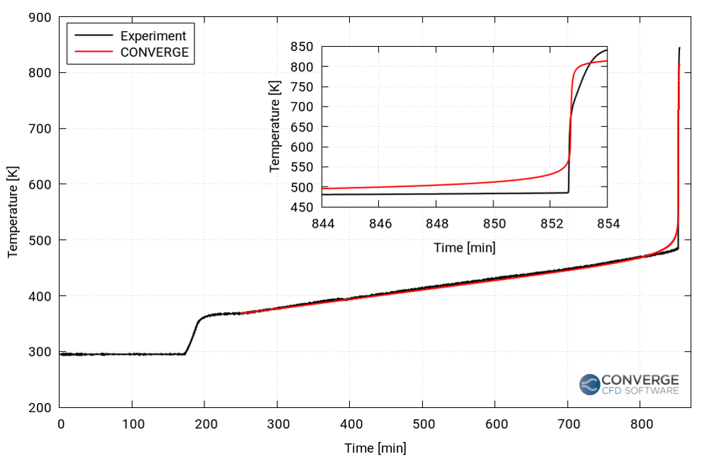
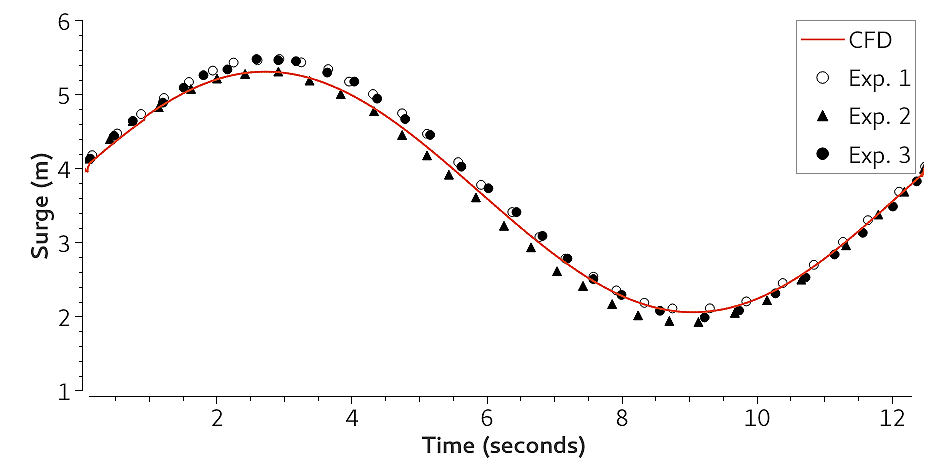
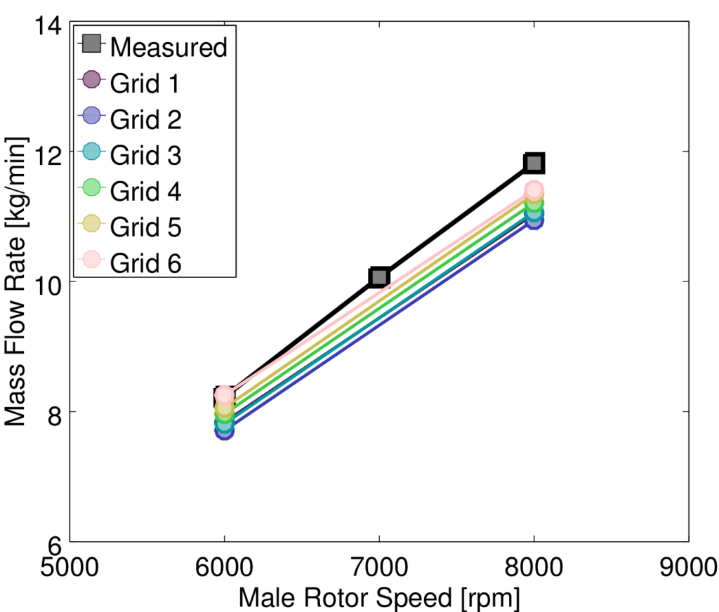
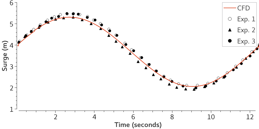
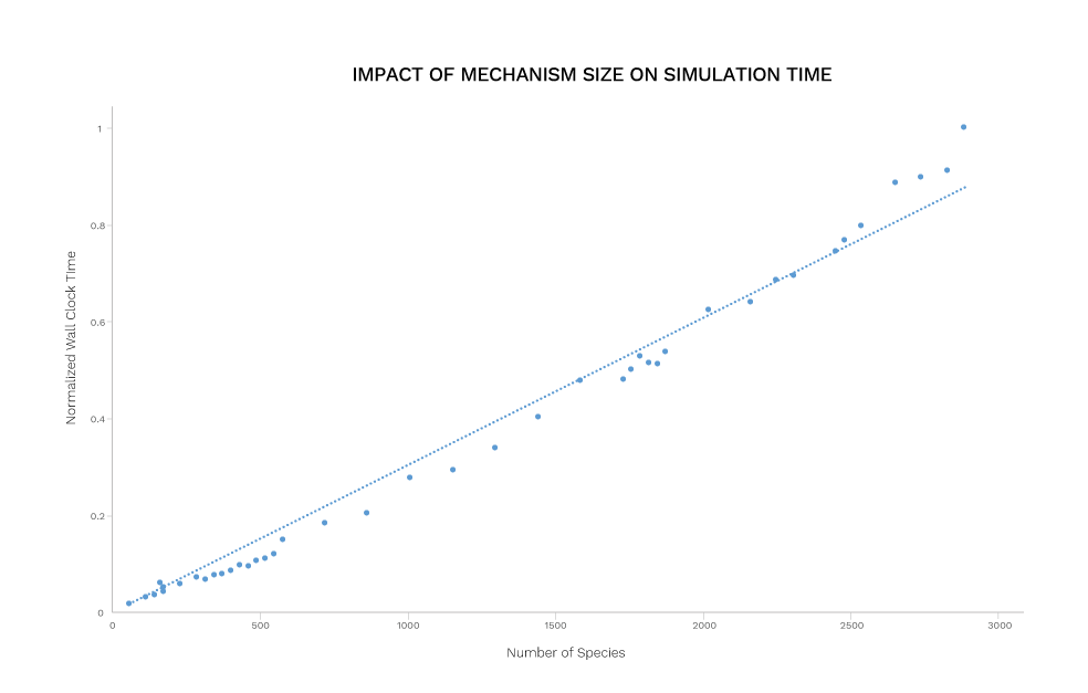
For both reducing mechanisms for chemistry and curve fitting for plots, whether a simplified view is worth it comes down to the context. If we say a plot is nearly linear when the curve fits with an R<sup>2</sup> of 0.9823, we are throwing away the 0.0177 that doesn’t fit. But it <em>works to describe the system</em> to the degree that&#8217;s needed in that moment. You need to have the ability to reduce that mechanism or fit that plot. So go out there. Take your ice pick. We’re not going to hobble you with a tape measure when you’ve got a mountain to climb.</p>
<div class="m-y-2" style="height: 1px; border-top: 1px solid #333;"></div>
<p><sup>1</sup> http://www.nationalgeographic.com/features/99/everest/roof_start.html<br />
<sup>2</sup> Korzybski, A. <em>Science and Sanity: An Introduction to Non-Aristotelian Systems and General Semantics</em>, Institute of General Semantics, 1933.<br />
<sup>3</sup> Pei, Y., Mehl, M., Liu, W., Lu, T., Pitz, W.J., and Som, S., &#8220;A Multi-Component Blend as a Diesel Fuel Surrogate for Compression Ignition Engine Applications,&#8221; <em>Journal of Engineering for Gas Turbines and Power</em>, GTP-15-1057, 2015.<br />
<sup>4</sup> Pei, Y., Mehl, M., Liu, W., Lu, T., Pitz, W.J., and Som, S., <em>SME 2014 Internal Combustion Engine Division Fall Technical Conference, Volume 2: Instrumentation, Controls, and Hybrids; Numerical Simulation; Engine Design and Mechanical Development; Keynote Papers</em>, Columbus, IN, USA, 2014.</p>
]]>
            </summary>
                                    <updated>2017-02-13T17:53:14+00:00</updated>
        </entry>
            <entry>
            <title><![CDATA[<em>Prediction</em> or <em>Postdiction</em>? In CFD, the Prefix Matters]]></title>
            <link rel="alternate" href="https://convergecfd.com/blog/prediction-postdiction-in-cfd" />
            <id>https://convergecfd.com/95</id>
            <author>
                <name><![CDATA[Kelly Senecal]]></name>
            </author>
            <summary type="html">
                <![CDATA[<p>If you’ve been following my blog series <em><a href="https://convergecfd.com/blog/toward-predictive-combustion-a-blog-series">Toward Predictive Combustion</a></em>, you know that at Convergent Science we are passionate about <em>predictions</em>. You’re probably thinking to yourself, “That’s obvious—you create CFD software!” But it’s actually less obvious than you might think. Much of the CFD that is performed today is still what I would call <em>postdictive</em>, even though it’s rarely referred to as such. According to <a target="_blank" href="https://en.wikipedia.org/wiki/Postdiction">Wikipedia</a>, postdiction is the act of making a prediction about the past or explaining something after the fact. At Convergent Science, we use this term to explain how simplified models, extensive tuning, and offset errors are used to match CFD results to existing experimental data. This is a common process, especially for combustion simulations. As an example, here’s a typical postdictive procedure for internal combustion engine simulations.</p>
<ol>
<li><strong>Someone performs an experiment</strong> (typically not the CFD engineer).</li>
<li><strong>The CFD engineer receives the experimental data</strong> (typically average pressure trace, apparent heat release rate, emission data, etc.).</li>
<li><strong>The CFD engineer sets up the case, including the geometry, and runs the simulation</strong>. Uncertainties in the inputs can have a large influence on the simulation results, but it can be difficult to resolve these uncertainties. For example, for a diesel engine, how well known is the nozzle orifice diameter? The actual value doesn’t always match the nominal value. Is the CAD surface available for the intake and exhaust ports, or is a swirl ratio based on steady-state flowbench results used? How well known is the start of injection timing? What about wall temperatures? The CFD engineer often has to simplify the case (for example, neglect the intake by simulating only an engine sector) because of these uncertainties.</li>
<li><strong>Likely the first simulation results don’t match the experimental data, and so the CFD engineer tunes the empirical spray and/or combustion models</strong>. By tuning I mean that the model constants are changed until the simulation results better match the experimental data. (As a side note, can we agree to quit calling these “constants”? Constant implies that they are never changed!)</li>
<li><strong>The CFD engineer changes physical inputs</strong> (start of injection timing, EGR level, injection pressure, etc.) <strong>and hopes that simulations run with the tuned models capture trends in outputs such as emissions</strong>.</li>
</ol>
<p>While there are advantages to this process (simulations typically run relatively quickly because of their coarse meshes, simplified domains, and empirical models), there are no guarantees that tuning will lead to simulation results that more closely match the experimental data. The final step in the process (identifying trends in outputs by running a series of simulations with the tuned models) doesn’t always work as well as desired. Moreover, the possibility of grid-dependent results from the coarse mesh often goes unchecked as the thought of recreating the grid is daunting.</p>
<p>In reviewing the above process, would you consider these simulation results <em>predictions</em> when a) it’s unclear if these simulations are using the correct physical inputs and b) the simulation results are predicated on the experimental data? I would argue that the simulations are <em>postdictions</em> because having the experimental results was critical to getting a “good” answer.</p>
<p><img class="aligncenter size-large wp-image-1097 img-fluid" src="https://cdn.convergecfd.com/predictiveICEngineSimulation-1024x813.jpg" alt="" width="840" height="667" srcset="https://cdn.convergecfd.com/predictiveICEngineSimulation-1024x813.jpg 1024w, https://cdn.convergecfd.com/predictiveICEngineSimulation-300x238.jpg 300w, https://cdn.convergecfd.com/predictiveICEngineSimulation-768x609.jpg 768w, https://cdn.convergecfd.com/predictiveICEngineSimulation-284x225.jpg 284w, https://cdn.convergecfd.com/predictiveICEngineSimulation-250x198.jpg 250w, https://cdn.convergecfd.com/predictiveICEngineSimulation-500x397.jpg 500w, https://cdn.convergecfd.com/predictiveICEngineSimulation-1200x952.jpg 1200w" sizes="(max-width: 709px) 85vw, (max-width: 909px) 67vw, (max-width: 1362px) 62vw, 840px" />
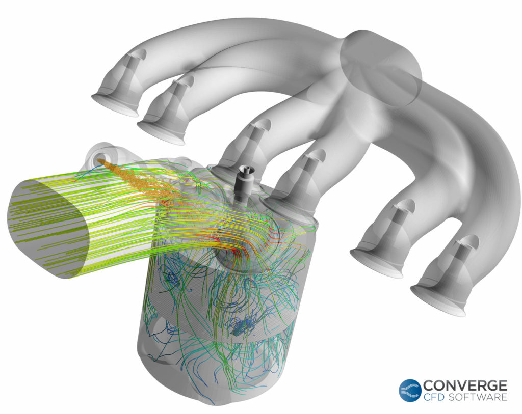
So, if this is a postdiction, then what’s a prediction? Imagine running a simulation with the exact physical inputs that would be used in the corresponding experiment, which has not been run. The simulation results <em>predict</em> the experimental results. A prediction is a forecast—an estimate of a future event—and it’s much more difficult to get right. It requires grid-convergent mesh settings (which are fairly straightforward with
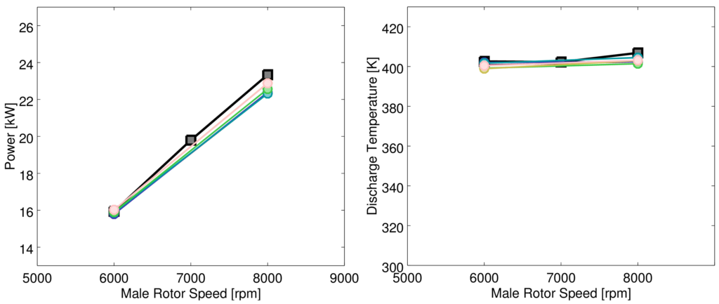
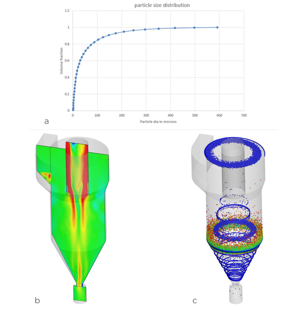
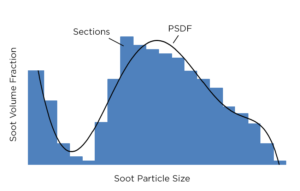
 <a href="https://convergecfd.com/benefits/automatic-adaptive-meshing">automatic and adaptive meshing</a>), more of the domain (not just a sector) to be simulated, detailed combustion models, high order numerics, the inclusion of unsteady behavior, more physics, and typically much longer runtimes.</p>
<p>One of the key differences between postdiction and prediction is that in a prediction there should be much more confidence in the answer that the CFD is giving you. As a result, if the simulation results don’t align with the experimental data, you might be suspicious of the physical inputs rather than the physical models. This goes back to uncertainties in the physical inputs (“<a target="_blank" href="https://en.wikipedia.org/wiki/Garbage_in,_garbage_out">garbage in, garbage out</a>”), which can be difficult to track down, but it’s well worth the effort.</p>
<p>So, which approach should you take for your next combustion simulation project? If you don’t have runtime constraints, a grid-converged mesh, detailed chemistry, and an LES turbulence model are your best bet for a predictive simulation. If you do have runtime constraints, a coarse mesh, an empirical combustion model, and a RANS-based turbulence model likely will get you a reasonable (postdictive) answer with a more affordable runtime. Keep in mind, however, that if tuning is required, the real runtime is the total time of all iterations simulated, not just the cost of a single calculation.</p>
<p>It is important to note that I’m not suggesting that predictive simulations never require tuning. Many state-of-the-art physical models still rely on some empiricism. On the flip slide, as long as you are aware of the errors, a postdictive approach can be successful for many types of CFD projects, and although many iterations may be required to tune the initial case, subsequent simulations may benefit from relatively short runtimes. The important thing is to be aware of what you’re running. Are your simulations <em>predictive</em> or <em>postdictive</em>? In CFD, the prefix matters.</p>
]]>
            </summary>
                                    <updated>2017-01-23T19:25:36+00:00</updated>
        </entry>
            <entry>
            <title><![CDATA[The Need for Detailed Soot Modeling in CFD]]></title>
            <link rel="alternate" href="https://convergecfd.com/blog/detailed-soot-modeling-in-cfd" />
            <id>https://convergecfd.com/94</id>
            <author>
                <name><![CDATA[Sarani Rangarajan]]></name>
            </author>
            <summary type="html">
                <![CDATA[<p>The <a href="https://www3.epa.gov/" target="_blank">United States Environmental Protection Agency</a> (US EPA) has strict standards to control the emissions polluting the air. The latest tier 3 standards are set to start from 2017 and immediately require a lower sulfur content in gasoline. These new regulations will apply to most vehicles on the road, barring only some heavy-duty vehicles. As a consequence of the new tier of regulations, the US EPA expects a significant reduction in emissions by 2030, including almost an 8000-ton reduction in fine particulate matter levels (PM 2.5). These regulations will bring the US on par with California, Europe, and South Korea.</p>
<p>If we want to protect our environment and our lungs (or sell cars, for that matter), we must learn to adapt existing systems to work more efficiently and comply with regulatory bodies. CONVERGE CFD can simulate the fundamental physical and chemical processes involved in the various stages of soot formation (particle inception, coagulation, condensation, and soot surface reactions). You can use empirical and phenomenological models to quickly estimate emissions. For a more detailed and accurate simulation of soot formation, CONVERGE leverages the SAGE detailed chemistry solver in two detailed soot models. Note that the SAGE solver requires a detailed mechanism that includes PAH chemistry. To make things easier for you, CONVERGE contains a tool for mechanism merging that can combine two mechanisms.</p>
<p><img class="aligncenter size-large-inline wp-image-886" src="https://cdn.convergecfd.com/CI-engine-combustion-simulation-500x407.jpg" alt="ci-engine-combustion-simulation" width="500" height="407" srcset="https://cdn.convergecfd.com/CI-engine-combustion-simulation-500x407.jpg 500w, https://cdn.convergecfd.com/CI-engine-combustion-simulation-300x244.jpg 300w, https://cdn.convergecfd.com/CI-engine-combustion-simulation-768x624.jpg 768w, https://cdn.convergecfd.com/CI-engine-combustion-simulation-1024x833.jpg 1024w, https://cdn.convergecfd.com/CI-engine-combustion-simulation-277x225.jpg 277w, https://cdn.convergecfd.com/CI-engine-combustion-simulation-250x203.jpg 250w, https://cdn.convergecfd.com/CI-engine-combustion-simulation-1200x976.jpg 1200w" sizes="(max-width: 500px) 85vw, 500px" /></p>
<p>Detailed soot modeling is applicable for a wide range of conditions and provides a host of data (including soot mass, number density, volume fraction, soot diameters, and surface area). Both of the CONVERGE detailed soot models are two-way coupled with the gas phase, meaning that soot formation affects gas phase chemistry and heat release, and vice versa. The two-way coupling means that your simulations results will provide a complete and accurate picture of soot formation as well as combustion.</p>
<p>The first detailed soot model, the Particulate Mimic (PM) model, uses the method of moments while the second, the Particulate Size Mimic (PSM) model, is based on sectional methods in which the solution is <img class="alignright size-medium wp-image-857" src="https://cdn.convergecfd.com/Blog_PSDF_no-outline-300x191.png" alt="blog_psdf_no-outline" width="300" height="191" srcset="https://cdn.convergecfd.com/Blog_PSDF_no-outline-300x191.png 300w, https://cdn.convergecfd.com/Blog_PSDF_no-outline-768x488.png 768w, https://cdn.convergecfd.com/Blog_PSDF_no-outline-354x225.png 354w, https://cdn.convergecfd.com/Blog_PSDF_no-outline-250x159.png 250w, https://cdn.convergecfd.com/Blog_PSDF_no-outline-500x318.png 500w, https://cdn.convergecfd.com/Blog_PSDF_no-outline.png 849w" sizes="(max-width: 300px) 85vw, 300px" /> obtained by solving sections (<i>i.e.</i>, bins) that contain particles of a similar size. The primary difference between the two is that the former assumes a particle size distribution function whereas the latter determines the particle size distribution in addition to the PM outputs.</p>
<p>CONVERGE Studio makes setting up these detailed models for complex soot formation and oxidation processes straightforward. To ensure that your PM and PSM simulations are as efficient as possible, CONVERGE includes acceleration strategies including multizone modeling and dynamic mechanism reduction. At the end of the day, the industry is moving toward a whole-system approach for simulating engines. No longer can we disconnect exhaust and emissions from combustion, since we don’t have the margin to accept the errors introduced by separate simulations. Even the US EPA considers the fuel and the vehicle a single integrated system. For accurate combustion and downstream simulation, it makes sense to use a single detailed chemistry solver to address the increasingly strict emissions challenges.</p>
]]>
            </summary>
                                    <updated>2016-12-01T03:38:02+00:00</updated>
        </entry>
            <entry>
            <title><![CDATA[Time-Savers in CONVERGE Studio]]></title>
            <link rel="alternate" href="https://convergecfd.com/blog/time-savers-in-converge-studio" />
            <id>https://convergecfd.com/93</id>
            <author>
                <name><![CDATA[Sarang Vijayraghavan]]></name>
            </author>
            <summary type="html">
                <![CDATA[<h4>Local coordinates</h4>
<p>Modern fuel-injected engines are geometrically complex, and such complexity makes every aspect of computational analysis more challenging. You might have passed off CAD duty to a colleague, and you can avoid discretizing the volume with CONVERGE’s automatic meshing and cut-cell capabilities, but there’s still the matter of injector configuration and setup. CONVERGE allows you to rapidly set up a local coordinate system (LCS) for each injector, avoiding the tedium and bookkeeping of manual coordinate transformations.</p>
<p>Consider the port fuel injected engine intake pictured here. The injectors (green) are not aligned with the global x, y, or z axes, nor are they aligned with each other. We will set up an LCS for each injector.</p>
<p><img loading="lazy" class="aligncenter size-large wp-image-660 p-y-2" src="https://cdn.convergecfd.com/CONVERGE-port-fuel-injected-engine-1024x749.png" alt="converge-port-fuel-injected-engine" width="840" height="614" srcset="https://cdn.convergecfd.com/CONVERGE-port-fuel-injected-engine-1024x749.png 1024w, https://cdn.convergecfd.com/CONVERGE-port-fuel-injected-engine-300x220.png 300w, https://cdn.convergecfd.com/CONVERGE-port-fuel-injected-engine-768x562.png 768w, https://cdn.convergecfd.com/CONVERGE-port-fuel-injected-engine-307x225.png 307w, https://cdn.convergecfd.com/CONVERGE-port-fuel-injected-engine-250x183.png 250w, https://cdn.convergecfd.com/CONVERGE-port-fuel-injected-engine-500x366.png 500w, https://cdn.convergecfd.com/CONVERGE-port-fuel-injected-engine-1200x878.png 1200w, https://cdn.convergecfd.com/CONVERGE-port-fuel-injected-engine.png 1932w" sizes="(max-width: 840px) 100vw, 840px" /></p>
<p>First, we use CONVERGE to calculate the spray axis by measuring the normal of the injector face and saving it to the Coordinate Cache. We also measure and save the centroid of the injector face. Then we go to Create &gt; Coordinates and copy the cached normal vector, saving it as a new LCS.</p>
<div class="flex p-y-2"><img loading="lazy" class="p-r-1 size-medium wp-image-661" src="https://cdn.convergecfd.com/CONVERGE-spray-axis-1-300x183.png" alt="converge-spray-axis-1" width="300" height="183" srcset="https://cdn.convergecfd.com/CONVERGE-spray-axis-1-300x183.png 300w, https://cdn.convergecfd.com/CONVERGE-spray-axis-1-768x468.png 768w, https://cdn.convergecfd.com/CONVERGE-spray-axis-1-1024x624.png 1024w, https://cdn.convergecfd.com/CONVERGE-spray-axis-1-369x225.png 369w, https://cdn.convergecfd.com/CONVERGE-spray-axis-1-250x152.png 250w, https://cdn.convergecfd.com/CONVERGE-spray-axis-1-500x305.png 500w, https://cdn.convergecfd.com/CONVERGE-spray-axis-1-1200x731.png 1200w, https://cdn.convergecfd.com/CONVERGE-spray-axis-1.png 1720w" sizes="(max-width: 300px) 100vw, 300px" /><br />
<img loading="lazy" class="size-medium wp-image-662" src="https://cdn.convergecfd.com/CONVERGE-spray-axis-2-300x184.png" alt="converge-spray-axis-2" width="300" height="184" srcset="https://cdn.convergecfd.com/CONVERGE-spray-axis-2-300x184.png 300w, https://cdn.convergecfd.com/CONVERGE-spray-axis-2-768x471.png 768w, https://cdn.convergecfd.com/CONVERGE-spray-axis-2-1024x627.png 1024w, https://cdn.convergecfd.com/CONVERGE-spray-axis-2-367x225.png 367w, https://cdn.convergecfd.com/CONVERGE-spray-axis-2-250x153.png 250w, https://cdn.convergecfd.com/CONVERGE-spray-axis-2-500x306.png 500w, https://cdn.convergecfd.com/CONVERGE-spray-axis-2-1200x735.png 1200w, https://cdn.convergecfd.com/CONVERGE-spray-axis-2.png 1720w" sizes="(max-width: 300px) 100vw, 300px" /></div>
<p>Next we open the nozzle configuration editor and change the coordinate system from Global to your new LCS. The spray plume is now oriented along one of the axes of the LCS, and any edits or adjustments are clean and simple.</p>
<p><img loading="lazy" class="aligncenter size-large wp-image-663 p-y-2" src="https://cdn.convergecfd.com/CONVERGE-spray-plume-1024x625.png" alt="converge-spray-plume" width="840" height="513" srcset="https://cdn.convergecfd.com/CONVERGE-spray-plume-1024x625.png 1024w, https://cdn.convergecfd.com/CONVERGE-spray-plume-300x183.png 300w, https://cdn.convergecfd.com/CONVERGE-spray-plume-768x469.png 768w, https://cdn.convergecfd.com/CONVERGE-spray-plume-368x225.png 368w, https://cdn.convergecfd.com/CONVERGE-spray-plume-250x153.png 250w, https://cdn.convergecfd.com/CONVERGE-spray-plume-500x305.png 500w, https://cdn.convergecfd.com/CONVERGE-spray-plume-1200x733.png 1200w, https://cdn.convergecfd.com/CONVERGE-spray-plume.png 1798w" sizes="(max-width: 840px) 100vw, 840px" /></p>
<h4>Surface refinement</h4>
<p>CONVERGE has no trouble with surfaces that are discretized with very high aspect ratio triangles, but some other computational packages aren’t so forgiving. CONVERGE Studio provides a quick and easy tool to coarsen or refine a surface discretization, providing a triangulation that is nearly isotropic.</p>
<p>This process is as simple as selecting the triangles you want to replace and then going to Geometry &gt; Create &gt; Triangle. Select the Refine Triangles option and choose your target edge length. With but a moment’s work, you can create a nearly isotropic surface triangulation suitable for export to the most demanding third-party software.</p>
<div class="flex p-y-2"><img loading="lazy" class="p-r-1 size-medium wp-image-665" src="https://cdn.convergecfd.com/CONVERGE-surface-refinement-2-300x233.png" alt="converge-surface-refinement-2" width="300" height="233" srcset="https://cdn.convergecfd.com/CONVERGE-surface-refinement-2-300x233.png 300w, https://cdn.convergecfd.com/CONVERGE-surface-refinement-2-768x596.png 768w, https://cdn.convergecfd.com/CONVERGE-surface-refinement-2-1024x795.png 1024w, https://cdn.convergecfd.com/CONVERGE-surface-refinement-2-290x225.png 290w, https://cdn.convergecfd.com/CONVERGE-surface-refinement-2-250x194.png 250w, https://cdn.convergecfd.com/CONVERGE-surface-refinement-2-500x388.png 500w, https://cdn.convergecfd.com/CONVERGE-surface-refinement-2-1200x931.png 1200w, https://cdn.convergecfd.com/CONVERGE-surface-refinement-2.png 1956w" sizes="(max-width: 300px) 100vw, 300px" /><br />
<img loading="lazy" class="size-medium wp-image-664" src="https://cdn.convergecfd.com/CONVERGE-surface-refinement-1-300x229.png" alt="converge-surface-refinement-1" width="300" height="229" srcset="https://cdn.convergecfd.com/CONVERGE-surface-refinement-1-300x229.png 300w, https://cdn.convergecfd.com/CONVERGE-surface-refinement-1-768x586.png 768w, https://cdn.convergecfd.com/CONVERGE-surface-refinement-1-1024x781.png 1024w, https://cdn.convergecfd.com/CONVERGE-surface-refinement-1-295x225.png 295w, https://cdn.convergecfd.com/CONVERGE-surface-refinement-1-250x191.png 250w, https://cdn.convergecfd.com/CONVERGE-surface-refinement-1-500x381.png 500w, https://cdn.convergecfd.com/CONVERGE-surface-refinement-1-1200x915.png 1200w, https://cdn.convergecfd.com/CONVERGE-surface-refinement-1.png 1996w" sizes="(max-width: 300px) 100vw, 300px" /></div>
]]>
            </summary>
                                    <updated>2016-11-01T18:38:45+00:00</updated>
        </entry>
            <entry>
            <title><![CDATA[Mathematical Acrobatics]]></title>
            <link rel="alternate" href="https://convergecfd.com/blog/mathematical-acrobatics" />
            <id>https://convergecfd.com/86</id>
            <author>
                <name><![CDATA[Clayton Grow]]></name>
            </author>
            <summary type="html">
                <![CDATA[<p>The <a href="http://www.theswingingsticks.com/how-swinging-sticks-works.php">Swinging Sticks</a> or Chaos Pendulum is the latest addition to the Convergent Science headquarters.</p>
<p><img loading="lazy" class="alignleft size-medium wp-image-5041" src="https://cdn.convergecfd.com/ChaosSticks-CSI-3-229x300.jpg" alt="ChaosSticks-CSI-3" width="229" height="300">
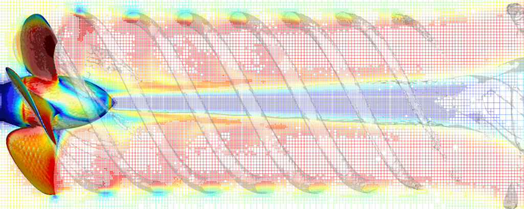
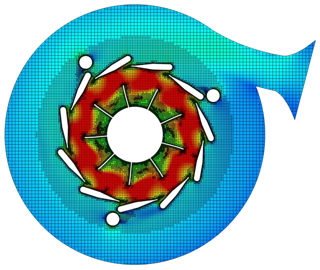
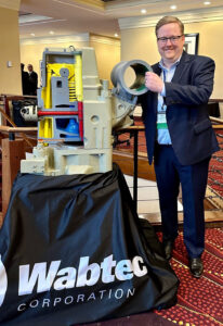
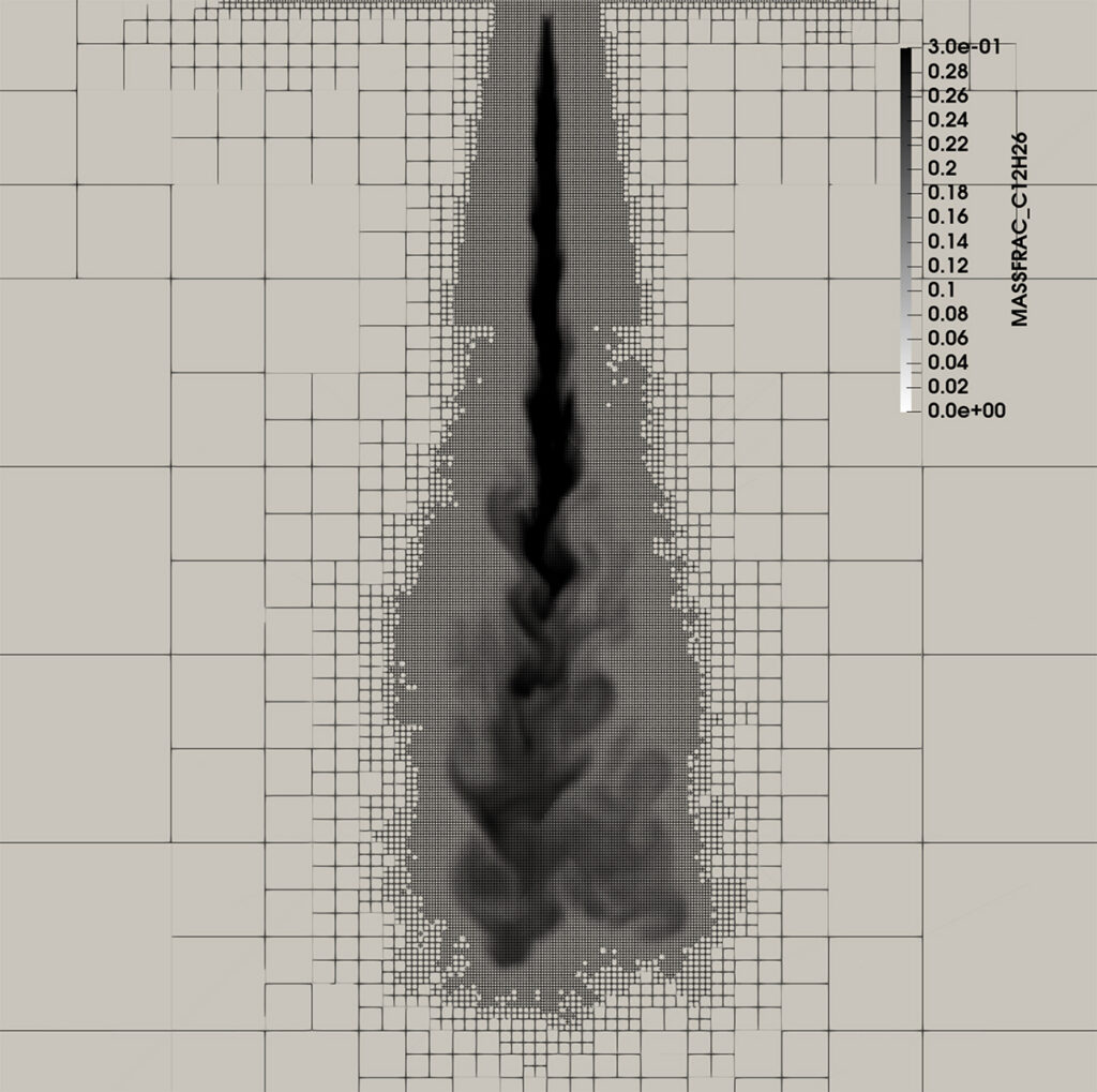
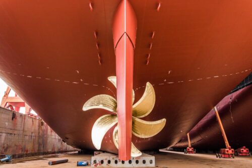
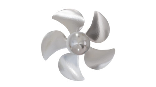
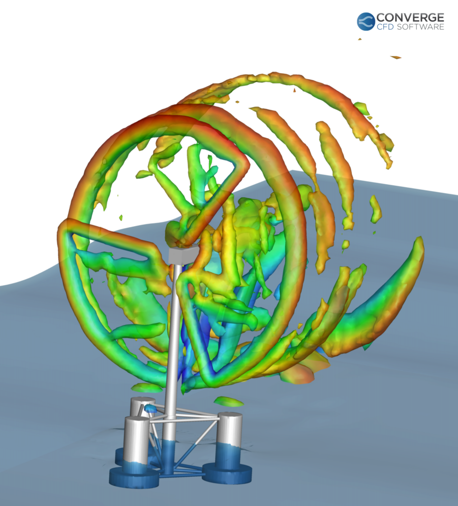
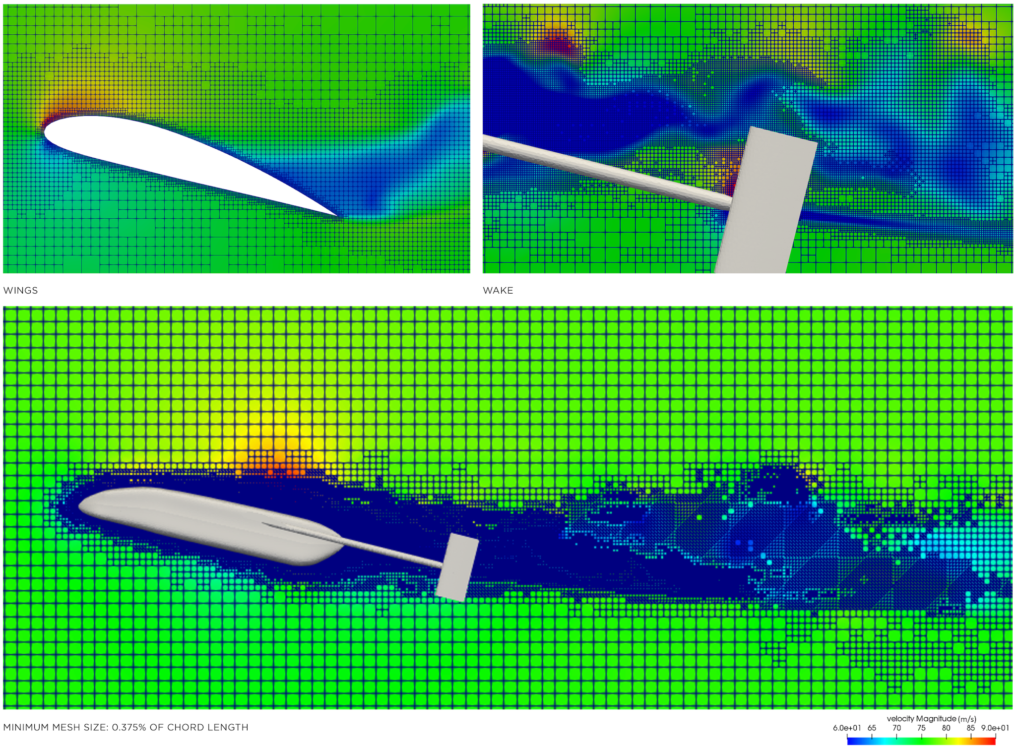
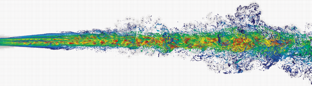
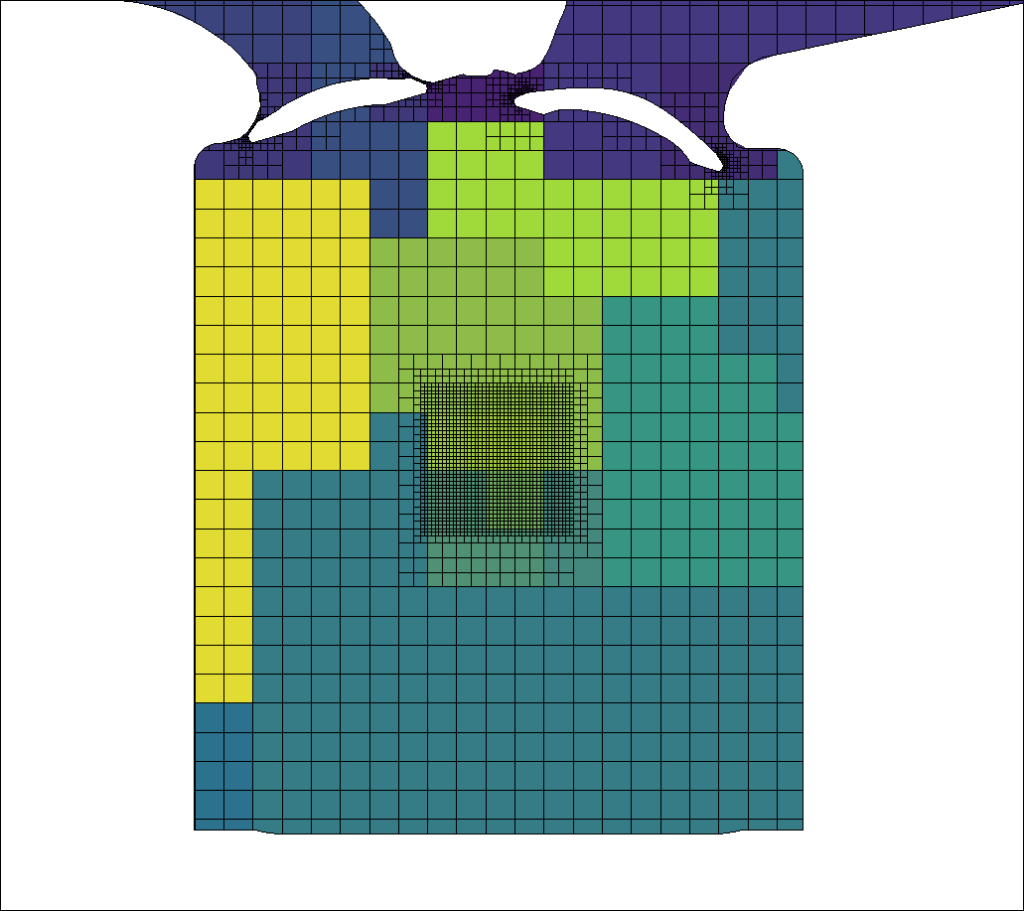
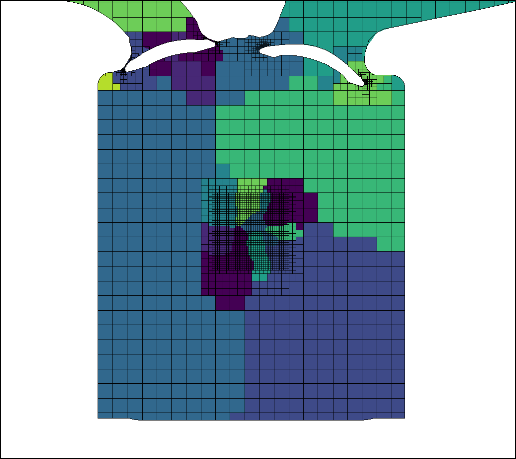
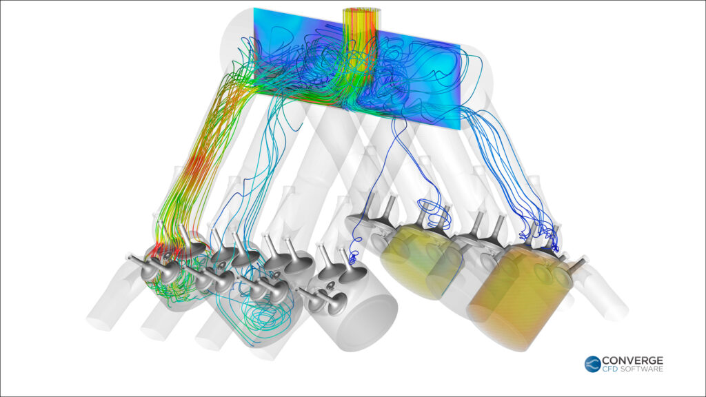
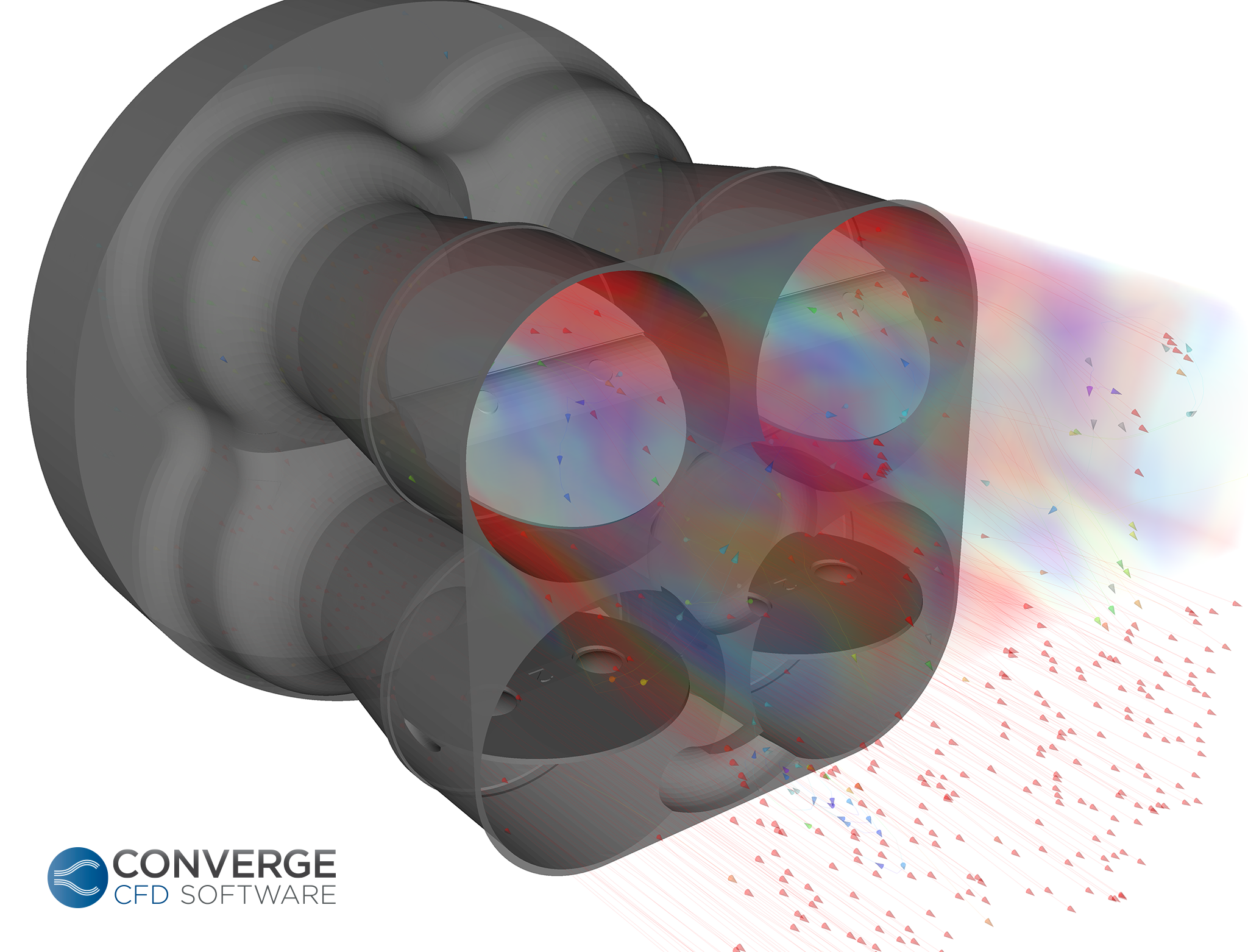
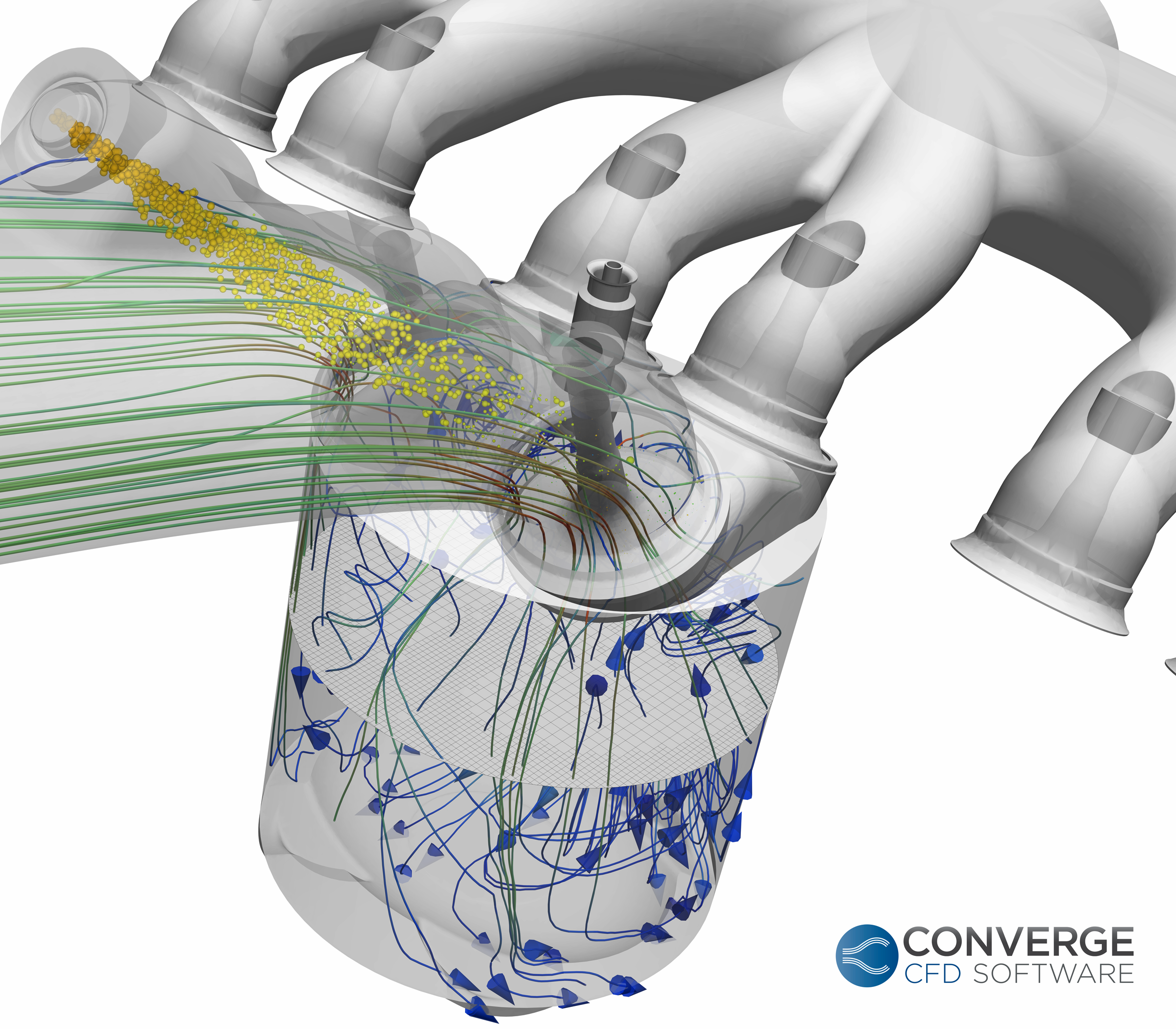
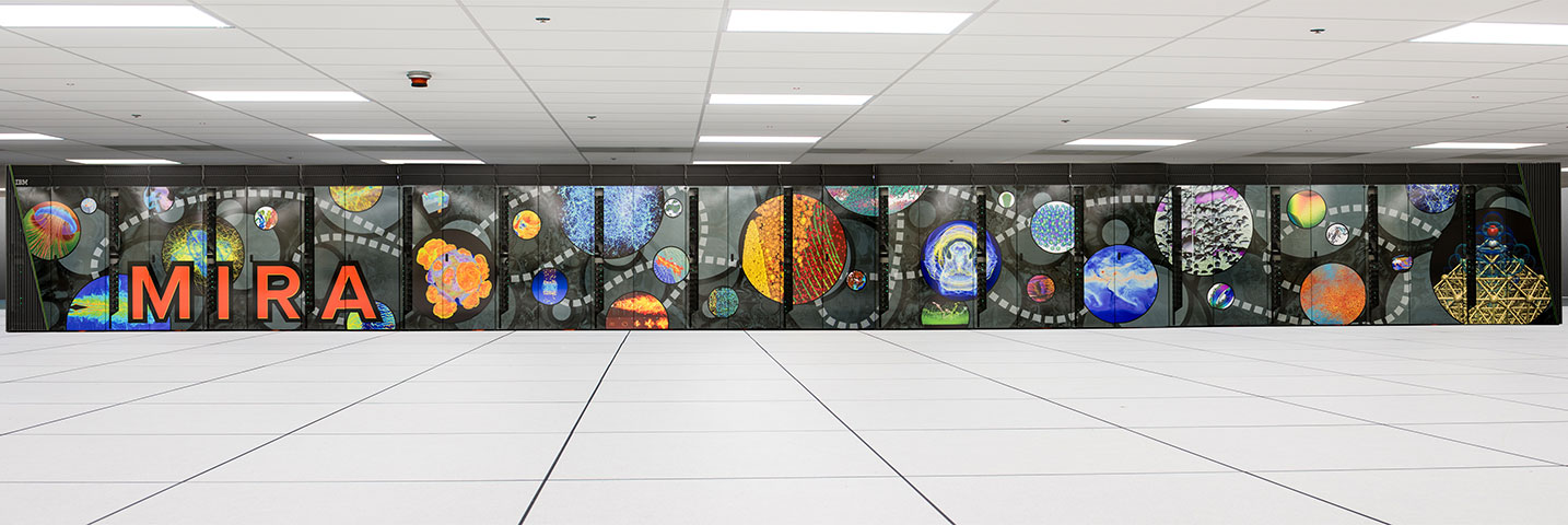
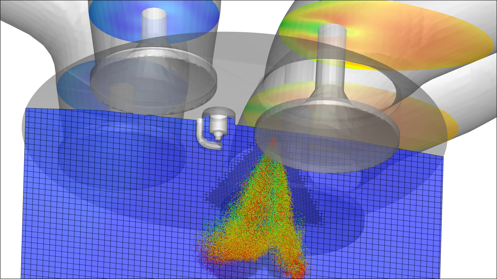
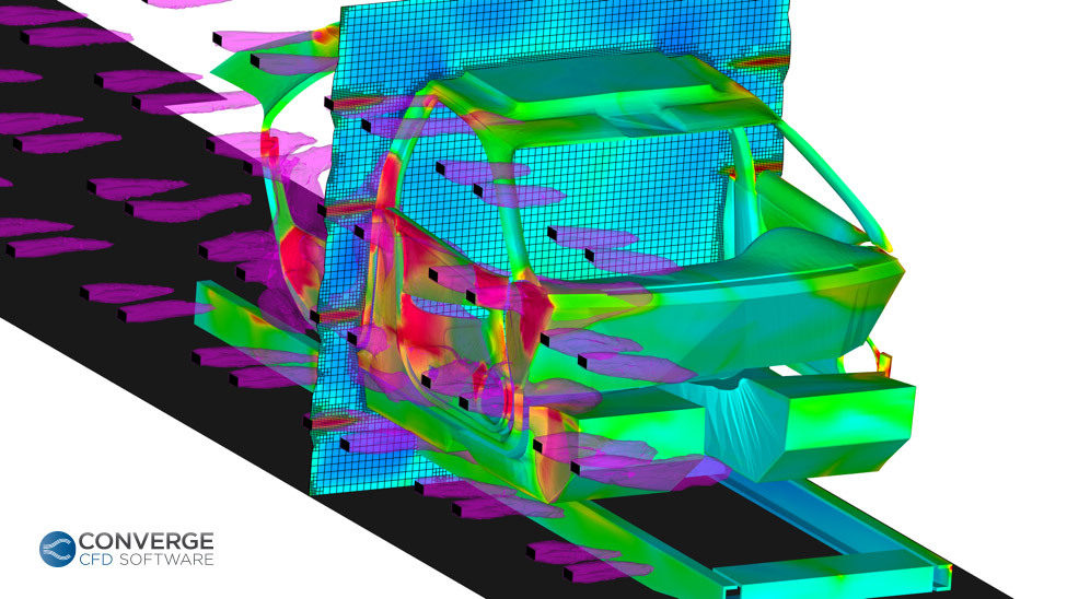
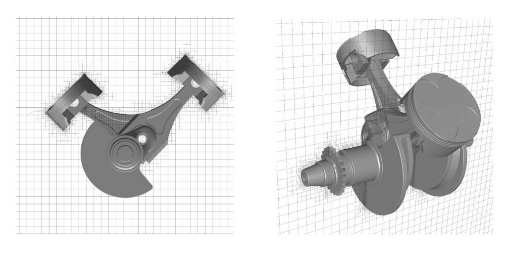
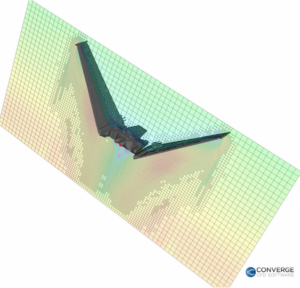
This kinetic sculpture embodies the essence of what makes CONVERGE CFD software unique: we can efficiently simulate chaos. Our CFD solver is mathematically and physically robust, and we allow the solver to predict where the mesh refinement is needed most.</p>
<p>Just like the Swinging Sticks, fluid flow in real-life, unsteady systems is complex and can be unpredictable. But just like the simplicity of the sculpture, CONVERGE provides you with a way to simulate chaos using a very simple set of input parameters.</p>
<p>A few weeks ago, this unrepeatable pattern concept was at the heart of a riveting company-wide discussion about cycle-to-cycle variation in unsteady systems. In a physical system, flow phenomena can vary from experiment to experiment, even when all of the initial conditions are identical, due to slight physical perturbations that grow and induce a larger effect on the flow as they propagate through the fluid domain. Some call this the <a href="https://en.wikipedia.org/wiki/Butterfly_effect">butterfly effect</a>.</p>
<p>Our discussion focused on how numerical perturbations can have this same effect on an unsteady system. These numerical perturbations can be caused by seemingly negligible rounding differences or changes to a random number seed. We are highly encouraged by our ability to predict this cycle-to-cycle variation in unsteady systems.</p>
<p>Despite how dry and technical “cycle-to-cycle variations in unsteady systems” sounds, the conversation was truly fascinating. Being in that room with a few dozen passionate PhDs, mechanical engineers, and CFD specialists was one of the most thought-provoking experiences I’ve ever had.</p>
<div class="embed-responsive embed-responsive-16by9"><iframe loading="lazy" src="https://www.youtube-nocookie.com/embed/ulottVdSlzQ?rel=0" width="560" height="315" frameborder="0" allowfullscreen="allowfullscreen" class="m-b-2"><br />
</iframe></div>
<p>If your application requires you to predict complex and unsteady fluid flow behavior, we can help you. Email me at&nbsp;clayton.grow@convergecfd.com&nbsp;if you’d like to see what CONVERGE CFD can do for you.</p>
]]>
            </summary>
                                    <updated>2016-08-31T21:23:26+00:00</updated>
        </entry>
            <entry>
            <title><![CDATA[No Mesh, No Mess: Repairing Dirty Surfaces with Polygonica]]></title>
            <link rel="alternate" href="https://convergecfd.com/blog/repair-dirty-surface-polygonica" />
            <id>https://convergecfd.com/85</id>
            <author>
                <name><![CDATA[Julian Toumey]]></name>
            </author>
            <summary type="html">
                <![CDATA[<p>For CONVERGE CFD simulations, you do not have to generate a volume mesh. The robust and efficient automatic mesh generation algorithm in CONVERGE does the work for you, accelerating your CFD workflow. Even though you do not have to generate a volume mesh, you may need to perform surface repair operations to ensure your CAD surface meets certain requirements. To make the surface repair process even easier, CONVERGE Studio v2.3 (the graphical pre-processor for CONVERGE) includes the Polygonica geometry libraries.</p>
<div id="attachment_4353" class="wp-caption alignright content" style="width: 376px;">
<p><a href="https://cdn.convergecfd.com/diagnosisdock_errors-R1.png"><img loading="lazy" class="wp-image-4353 size-full" src="https://cdn.convergecfd.com/diagnosisdock_errors-R1.png" alt="diagnosisdock_errors-R1" width="366" height="408" /></a></p>
<p class="wp-caption-text">Diagnosis dock in CONVERGE Studio used to identify surface errors such as intersections and open edges. This surface has 2246 intersections and 40 open edges.</p>
</div>
<p>With an appropriate license, the Polygonica toolkit is integrated seamlessly into CONVERGE Studio v2.3. You have access to the Coarsen, Boolean, and Healing tools to quickly fix problems with a surface.</p>
<p>To demonstrate the efficiency of the surface repair process with CONVERGE Studio and Polygonica, let’s consider the following example. This geometry is of a two-stroke engine and is freely available via Solidworks Zen.</p>
<p>We use the Diagnosis dock in CONVERGE Studio to identify surface errors such as intersections and open edges. This surface has 2246 intersections and 40 open edges.</p>
<p>In the figure below, the error-free triangles are rendered in gray and the intersections and open edges are rendered in red. Many of the errors occur where the connecting rods meet the crankshaft.</p>
<div class="center-text" style="margin-top: 2em;"><a href="https://cdn.convergecfd.com/image1.png"><img loading="lazy" class="alignnone wp-image-4336 size-medium" src="https://cdn.convergecfd.com/image1-300x300.png" alt="image1" width="300" height="300" /></a> <a href="https://cdn.convergecfd.com/image2.png"><img loading="lazy" class="alignnone wp-image-4337 size-medium" src="https://cdn.convergecfd.com/image2-300x300.png" alt="image2" width="300" height="300" /></a></div>
<p>The intersections, which may occur when creating an assembly from individual CAD parts, prevent the surface from meeting the requirements for CONVERGE. Manually repairing the surface would require a combination of moving, deleting, and recreating triangles, and would be time-intensive. Instead, we will leverage the Polygonica toolkit.<a href="https://cdn.convergecfd.com/image3.png"><img loading="lazy" class="aligncenter wp-image-4338 size-medium" src="https://cdn.convergecfd.com/image3-300x300.png" alt="image3" width="300" height="300" /></a></p>
<p>&nbsp;</p>
<p>We can slightly coarsen the geometry with Polygonica to repair the intersections and open edges without a large reduction in surface fidelity. Coarsening a surface reduces the number of triangles based on the criteria that you specify. Polygonica’s powerful and efficient algorithms attempt to avoid intersections and open edges in the coarsened surface.</p>
<p>The original surface has approximately 295,000 triangles and we will reduce this number by about 5%. To use the Polygonica Coarsen tool, we open the Geometry dock in CONVERGE Studio. For the coarsening criteria, we set the minimum number of triangles to 280,000 and leave the other settings as the default options. Coarsen the entire surface.</p>
<p><img loading="lazy" class="aligncenter wp-image-4355" src="https://cdn.convergecfd.com/image4-R1-1024x530.png" alt="image4-R1" width="631" height="314" />
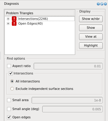
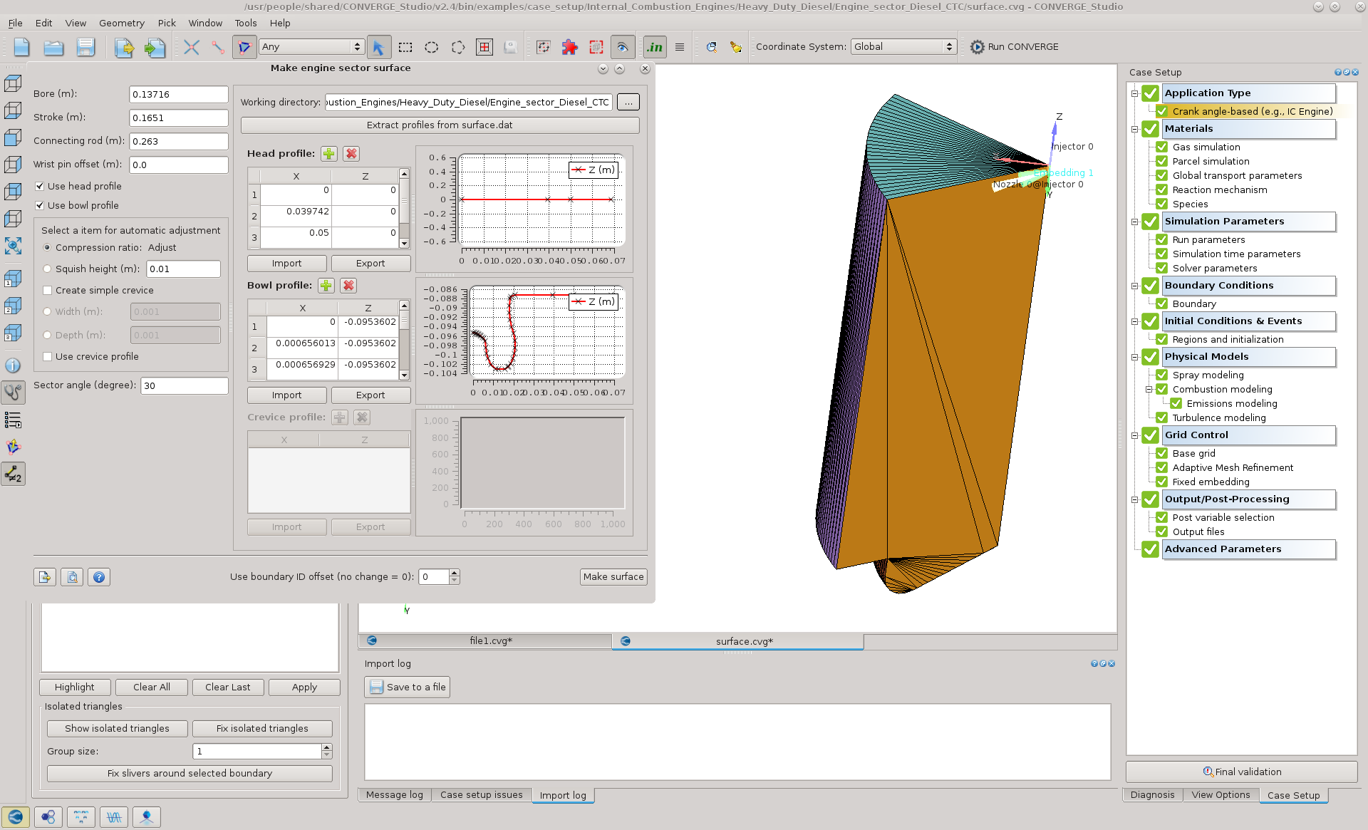
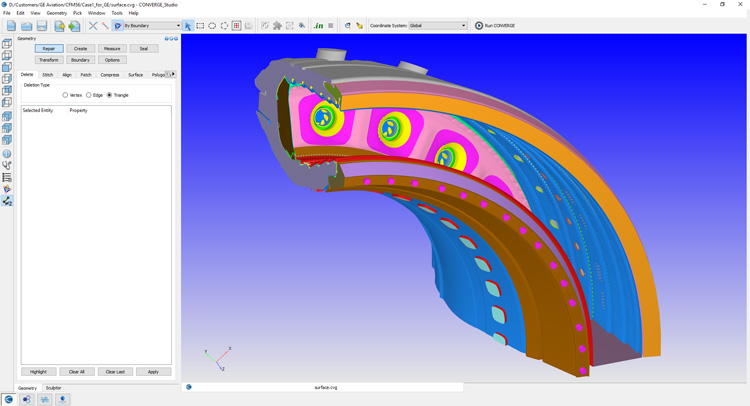
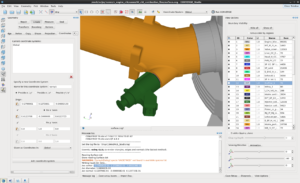
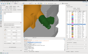
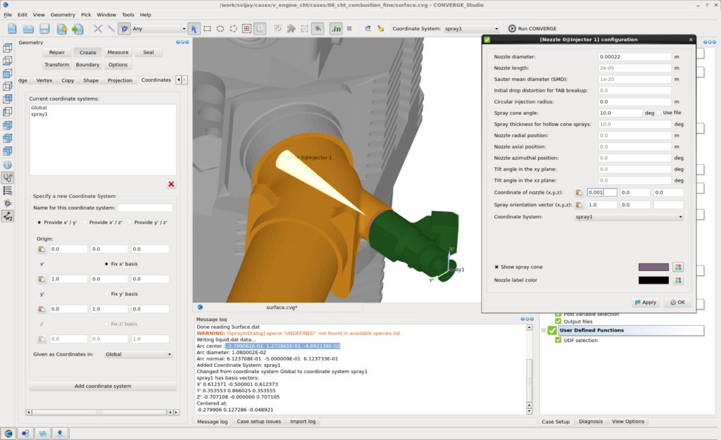
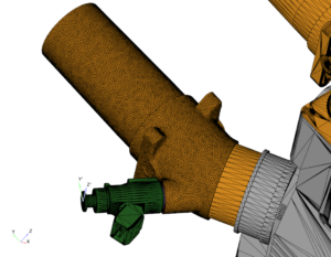
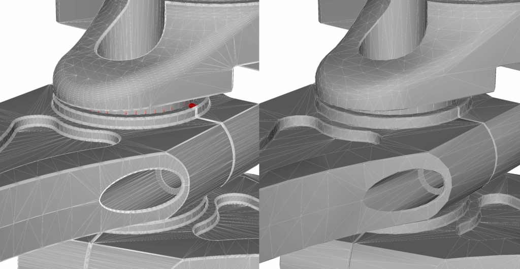
In the above image, the left frame shows the original surface with the intersections in red. The right frame shows the coarsened surface with the intersections and open edges repaired.</p>
<p><img loading="lazy" class="wp-image-4332 size-full alignright" src="https://cdn.convergecfd.com/diagnosisdock_cleaned.png" alt="diagnosisdock_cleaned" width="369" height="108" />
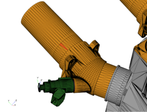
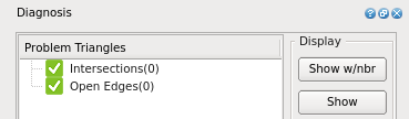
After coarsening the surface, the Diagnosis dock indicates that there are no longer intersections or open edges. Once we address the remaining requirements for the surface, the surface is ready to simulate in CONVERGE–no meshing required.</p>
<div id="attachment_4340" class="wp-caption aligncenter content" style="width: 310px;">
<p><img loading="lazy" class="wp-image-4340 size-medium" src="https://cdn.convergecfd.com/image5-300x300.png" alt="image5" width="300" height="300" /></p>
<p class="wp-caption-text"><span class="bold"> Left</span>: The spline shaft of the original geometry.<br />
<span class="bold"> Right</span>: The spline shaft after coarsening with Polygonica.</p>
</div>
<p>Polygonica makes repairing surface errors in CONVERGE Studio v2.3 much easier and further accelerates your CFD workflow.</p>
<div id="attachment_4343" class="wp-caption aligncenter content" style="width: 1034px;">
<p><img loading="lazy" class="wp-image-4343 size-large" src="https://cdn.convergecfd.com/grid12-1024x512.png" width="1024" height="512" /></p>
<p class="wp-caption-text">Cut-plane view of the volume mesh as generated automatically by CONVERGE.</p>
</div>
]]>
            </summary>
                                    <updated>2016-05-23T15:49:21+00:00</updated>
        </entry>
            <entry>
            <title><![CDATA[Under Pressure: Relief from the Pain of Meshing for Pressure Relief Valve and Reciprocating Compressor Simulations]]></title>
            <link rel="alternate" href="https://convergecfd.com/blog/mesh-pressure-relief-valve-reciprocating-compressor" />
            <id>https://convergecfd.com/84</id>
            <author>
                <name><![CDATA[Clayton Grow]]></name>
            </author>
            <summary type="html">
                <![CDATA[<p>As we explore new applications for CONVERGE, we look for products in which the flow and motion might be problematic for other CFD programs to capture. In the past year, we found an application that shared many characteristics with our flagship application, internal combustion engines: the reciprocating compressor. The two applications share a few key components: a cylinder, a piston reciprocating inside it, intake valves, and exhaust valves. In fact, a reciprocating compressor is sort of like an engine in reverse; instead of the volume of the cylinder expanding due to combustion driving the piston, the piston is controlled by outside forces, and the piston then compresses the gas inside the chamber. While these two mechanisms have many features in common, there are some major differences. The obvious difference: no combustion in a compressor. But there is a compressor phenomenon that is equally challenging to simulate: fluid-structure interaction of the pressure relief valves that control flow into and out of the compression chamber.</p>
<h3>Steady as She Goes</h3>
<p>Many of the pressure relief valve and compressor manufacturers have limited their CFD studies to steady-state flow. The main reason for this: making the mesh to accommodate the motion of objects with unprescribed motion can be quite difficult.</p>
<p>This is not to say that steady-state pressure relief valve simulations are without value; they can indeed provide useful insight early in the design cycle. But in order to understand some of the more complex flow phenomena near a pressure relief valve, designers need a more detailed analysis of how the flow evolves over time.</p>
<h3>The Distance</h3>
<p>One of the most critical phases of the compression cycle is the moment at which the gas begins to flow through an inflow or exhaust valve. When designers use traditional meshing methods and automated meshing scripts, they often need to guess the proper grid resolution and cell orientation in this small valve gap. Such an estimation can be problematic because as the gap grows, these cells need to either stretch or move to accommodate the valve motion. These stretching and moving cells can cause errors in the transport of calculated conditions (velocity, turbulence, species, etc.). These errors can propagate and cause major discrepancies in the results.<br />
<img decoding="async" loading="lazy" class="alignright size-medium wp-image-4034" src="https://cdn.convergecfd.com/Reciprocating-Compressor-Simulation-CONVERGE.png" alt="Simulation of reciprocating compressor" width="300" height="288"><br />
With CONVERGE, simply choose a base grid size and a level of refinement that will ensure the minimum number of layers of cells will fit in the smallest gap. The mesh never moves in CONVERGE; the solver regenerates the mesh each time-step to accommodate the motion of any part, prescribed or flow-driven. CONVERGE automatically generates the mesh in the small gap through a pressure relief valve, with no cell orientation transport errors — the mesh is always perfectly orthogonal. This makes the simulation setup for this critical area much simpler, easier, and the results more accurate.</p>
<h3>What’s the Frequency, Kenneth?</h3>
<p>Another important concept to study in a reciprocating compressor or a pressure relief valve is the frequency of the check valve motion and the frequency of the pressure waves caused by the motion of the valves and the piston. Pressure waves are inherently transient, so simulating them with a steady-state solver is problematic and requires many significant assumptions. Without the burden of creating and fine-tuning a mesh for every time-step, CONVERGE offers the ability to capture the shape and frequency of these pressure waves with Adaptive Mesh Refinement. In areas where there is a steep gradient in the velocity of a gas — often near the valve upon opening, CONVERGE automatically adds refinement to capture the precise shape of the pressure wave. You can control the refinement by choosing values for a few simple parameters in the Adaptive Mesh Refinement dialog box.</p>
<h3>Pinball Wizard</h3>
<p>“Tilt” is the dreaded nemesis of any pinball wizard. The tilt of a plate in a valve can also affect the pressure in different areas of a compressor in unexpected ways. CONVERGE offers a 6- degree-of-freedom (6DOF) fluid-structure interaction model that can accurately simulate the tilt of a plate valve pushed open against the dynamic resistance of a spring.</p>
<p>In much the same way a Pinball Wizard needs to have a good idea of how hard a pinball bounces off of a flapper, valve and compressor designers need to have a good idea how the valve bounces off the valve seat. CONVERGE’s options for contact modeling can simulate the bounce of the valve against the valve seat. The fully coupled, fully automated meshing at runtime in CONVERGE captures this bouncing valve with utmost precision.</p>
<p>Whether designing a pressure relief valve or a reciprocating compressor, CONVERGE offers the tools needed to capture the complex flow structures and the fluid-structure interactions that are vital to the design of these products that are used in a wide variety of industrial and household applications.</p>
]]>
            </summary>
                                    <updated>2016-04-18T05:50:43+00:00</updated>
        </entry>
            <entry>
            <title><![CDATA[A Call to Order]]></title>
            <link rel="alternate" href="https://convergecfd.com/blog/a-call-to-order" />
            <id>https://convergecfd.com/83</id>
            <author>
                <name><![CDATA[Kelly Senecal]]></name>
            </author>
            <summary type="html">
                <![CDATA[<p><em>From the <a href="https://convergecfd.com/blog/toward-predictive-combustion-a-blog-series">Toward Predictive Combustion</a> blog series</em></p>
<p>A long time ago in a galaxy far, far away… I wrote my last blog! Why has it taken me so long to blog again? Really there’s no excuse, but we at Convergent Science have been busy adding offices, forming partnerships, hosting user conferences, and expanding the CONVERGE user base. One thing that hasn’t changed is our dedication to bringing our users the most accurate CFD software for simulating flow and combustion in complex geometries.</p>
<p>An often overlooked concept that is critical to achieving reliable CFD results is order of accuracy. This concept is something that every CFD student learns about and every CFD user should understand. But what is it? It’s all about error. A numerical algorithm is nth order accurate if its error is proportional to the computational cell size to the nth power. In other words, if a method is first order accurate (e.g., first order upwinding), its error shrinks linearly as the cell size is reduced. A method that is second order accurate (e.g., second order central) has its error shrink in a quadratic manner. So what does order of accuracy have to do with predictive combustion modeling? Patience you must have my young <a href="http://starwars.wikia.com/wiki/Padawan">Padawan</a>…</p>
<p>If you’ve seen Star Wars: The Force Awakens, then you’re familiar with the First Order, an organization fighting for control of the galaxy. In the official novelization of the movie (according to <a href="http://starwars.wikia.com/wiki/First_Order">Wookieepedia</a>), Kylo Ren proclaims, “It is the task of the First Order to remove the disorder from our own existence, so that civilization may be returned to the stability that promotes progress.”<br />
<img decoding="async" loading="lazy" src="https://cdn.convergecfd.com/Adaptive-Mesh-Kelly-blog-300x288.png" alt="Mesh of Kylo Ren's command shuttle" width="300" height="288" class="alignright size-medium wp-image-4034"><br />
So the goal of the First Order is to remove disorder and return stability. This is exactly what first-order upwinding does to a CFD solution through numerical viscosity! However, by removing the disorder, the smeared flow field will suffer from reduced accuracy and can give a false sense of repeatability for systems that are inherently nonlinear. For example, if you examine 100 cycles of experimental pressure traces from a gasoline direct injection engine, most likely you will see significant cycle-to-cycle variation due to perturbations in one or more quantities. If you simulate this engine with first-order upwinding, however, you are likely to see very similar pressure traces for all 100 cycles, even with similar perturbations. Although a repeatable result may be desirable, you must proceed with caution when simulating combustion systems that exhibit chaotic behavior. Why? Because the cycle you obtain may not resemble the average behavior of the system and because it’s often the extreme cycles that lead to phenomena such as engine knock and high emissions.</p>
<p>A higher order scheme such as second-order central differencing is much more likely to capture complex phenomena such as engine knock and high emissions, and, indeed, second-order central is recommended to achieve accurate results. Nonetheless, local non-monotonic behavior in the solution can lead to instabilities and possibly crashes, and, like the First Order, adding some amount of first-order upwinding is necessary to reduce the disorder of the system and to maintain stability in the solution. It just goes to show that, every so often, even numerical schemes can surrender to the power of the dark side.</p>
<ul class="italic">
<li>
Part One: <a href="https://convergecfd.com/blog/toward-predictive-combustion-a-blog-series">Toward Predictive Combustion</a> a&nbsp;blog series</li>
<li>Part Two: <a href="https://convergecfd.com/blog/automatic-meshing-for-the-people-from-the-toward-predictive-combustion-blog-series">Automatic Meshing For The People</a></li>
<li>Part Three: <a href="https://convergecfd.com/blog/now-available-in-hd-from-the-toward-predictive-combustion-blog-series/">Now Available In HD</a></li>
</ul>
]]>
            </summary>
                                    <updated>2016-03-21T08:00:13+00:00</updated>
        </entry>
            <entry>
            <title><![CDATA[Now Available in HD]]></title>
            <link rel="alternate" href="https://convergecfd.com/blog/now-available-in-hd-from-the-toward-predictive-combustion-blog-series" />
            <id>https://convergecfd.com/92</id>
            <author>
                <name><![CDATA[Kelly Senecal]]></name>
            </author>
            <summary type="html">
                <![CDATA[<p><em>From the <a href="https://convergecfd.com/blog/toward-predictive-combustion-a-blog-series">Toward Predictive Combustion</a>&nbsp;blog series</em><br />
<img decoding="async" loading="lazy" class="alignright size-full wp-image-898" src="https://cdn.convergecfd.com/Screen-Shot-2014-01-20-at-9.49.33-AM-157x200-1.png" alt="Screen-Shot-2014-01-20-at-9.49.33-AM-157x200" width="157" height="200"></p>
<p>Years ago, on Black Friday no less, I remember coming home with my first High Definition Television. At that time there were only limited HD shows available, however I found myself trading good TV for stunning image quality.&nbsp;Once I caught a glimpse of a high resolution broadcast, the Standard Definition Television that had been perfectly fine for years up until hours beforehand suddenly became unbearable to watch. And why should I settle for 480i when 720p or 1080i was available? Now, several years later, virtually all television is available in High Definition. Fortunately for engineers, similar progress in resolution is being made in the world of Computational Fluid Dynamics (CFD). But more on that in a minute.</p>
<p>One of my biggest pet peeves is the phrase “grid&nbsp;independent.” Grid independence implies that you can get&nbsp;the same answer with any mesh.<em> Any cell size, any cell&nbsp;shape.</em> If you’re an experienced CFD user you know that&nbsp;the idea of a grid independent result is a pipe dream. The&nbsp;only way to achieve this is to employ such extensive&nbsp;empiricism that you are throwing out all or part of the CFD&nbsp;solution. When presented with such a grid independent model the user should be highly skeptical of its applicability outside of a small window of problems.</p>
<div title="Page 1"></div>
<p>“Grid independence” is also sometimes incorrectly used to describe “grid convergence.” In other words, as the mesh is refined, do the results eventually converge to an answer? Even better, do the results converge to the<em> right</em> answer? Think of grid convergence as HDTV with the CFD domain as the television screen. Standard definition is a coarse mesh with fuzzy images. As the domain is refined, the image starts to become clearer and clearer until further resolution doesn’t show a noticeable difference. A 720p HDTV image is 1280×720 or 921,600 pixels per frame. A 1080p HDTV image is 1920×1080 or 2,073,600 pixels per frame. To the casual viewer, these two resolutions may not look noticeably different, but both look significantly better than 480i SDTV at 345,600 pixels per frame (as a side note, I recently saw a stunning new UHD TV which may just be the DNS of television broadcasting).</p>
<p>So how do we obtain HD resolution for our fluid dynamics simulations? In CFD, higher resolution comes from adding cells, similar to adding pixels. However, the HD-equivalent of a fluid calculation comes at a very high computational cost. Fortunately, something called Adaptive Mesh Refinement (AMR) can be used so that resolution is only added where it is needed to keep the solution crisp. Think of AMR as adding pixels on your TV screen just in places where the color gradients are high. Neat idea, right? Well, it turns out that researchers at the University of California, Irvine are already looking at this type of functionality for image displays through a process called “Optical Pixel Sharing” (details can be found <a href="http://www.ics.uci.edu/%7Ebsajadi/files/pixelshare.pdf">here</a>). To quote their paper:</p>
<p style="padding-left: 30px;"><em>We explore, for the first time, the concept of variable spatial resolution display – a display that does not provide uniform density of pixels everywhere but allocates higher densities at specific regions of interest based on the content.</em></p>
<p>That sounds just like AMR! If optical pixel sharing was to be done on a movie, would it make sense to distribute pixels on the first frame and then hold those fixed throughout? Would it make sense for the viewer to guess where the resolution should go? The answer to these questions is “no!” Why? An explosion may occur in the upper left-hand corner of your TV in one part of a movie, but later this portion of the screen may contain a very uniform night sky. Seems obvious, but this is what most CFD users do with their computational grids – <em>they make them ahead of time</em>. To see the problem with this, check out the image below of a combusting jet in a cross flow.<img decoding="async" loading="lazy" class="aligncenter wp-image-897" src="https://cdn.convergecfd.com/jetincrossflow1-1024x430-1024x430-1.png" alt="jetincrossflow1-1024x430" width="600" height="252"></p>
<p>This image shows the temperature field and the computational mesh for one instance in time. The geometry for this case is very straightforward, but check out the crazy mesh that’s needed to resolve the flow! This says that even for a simple geometry it doesn’t make sense to create the mesh ahead of time. If you must start with a user-generated mesh your options are either a) live with standard definition, fuzzy CFD, or b) shell out the big bucks and put high resolution everywhere in the domain. Given those options, I’d let the solver make the mesh for me. Given those options, I’d count on AMR – it’s HD at a price we can all afford.</p>
<ul class="italic">
<li>
Part One: <a href="https://convergecfd.com/blog/toward-predictive-combustion-a-blog-series">Toward Predictive Combustion</a> a blog series</li>
<li>Part Two: <a href="https://convergecfd.com/blog/automatic-meshing-for-the-people-from-the-toward-predictive-combustion-blog-series">Automatic Meshing For The People</a></li>
<li>Part Four: <a href="https://convergecfd.com/blog/a-call-to-order">A Call To Order</a></li>
</ul>
]]>
            </summary>
                                    <updated>2014-01-20T06:09:14+00:00</updated>
        </entry>
            <entry>
            <title><![CDATA[The ABC’s of Limiting User-to-User Mesh Variations]]></title>
            <link rel="alternate" href="https://convergecfd.com/blog/the-abcs-of-limiting-user-to-user-mesh-variations" />
            <id>https://convergecfd.com/91</id>
            <author>
                <name><![CDATA[Convergent Science]]></name>
            </author>
            <summary type="html">
                <![CDATA[
<div id="attachment_4079" style="width: 160px" class=" wp-caption  alignright">
<img loading="lazy" decoding="async" class="size-thumbnail" src="https://cdn.convergecfd.com/RobKaczmarekheadshot.png" width="150" height="150">
<p>
 <span class="bold">Author: <br> Rob Kaczmarek</span>
 <br> <span style="text-transform: none;">Director of Global Marketing</span>
</p>
</div>


<figure class="wp-block-image alignright"><img decoding="async" src="https://cdn.convergecfd.com/RJK-July-31-300x199-1.jpg" alt="RJK-July-31-300x199" class="wp-image-927"/></figure>


<p>We’ve all experienced it… The old “Our group in ‘<em>pick your location’</em> is getting very different results from ours.” When it comes to CFD there have been numerous advances in the types of meshing technologies used: tetrahedral, hexahedral, polyhedral, chimera, etc., but little has been done until recently to limit the user-to-user variations from the mesh. We’ve assembled the top three ways to limit your user-to-user variations.</p>


<h3 class="wp-block-heading">Automate, Automate, Automate</h3>


<p>Meshing automation has arrived in various manifestations and it looks to be the best solution to the issue, if done right. This new innovative feature can take the human error out of any simulation, ensuring that case after case is consistent. While the “automated meshing” of a few years ago was clunky, mostly scripted, and not truly automated at all, the present day automated meshing is stable and validated. In some cases meshing automation has opened the door for grid refinement studies proving the technology is fully mature and one of the best ways to limit user-to-user meshing variations.</p>


<h3 class="wp-block-heading">Best Practices</h3>


<p>Assembling a best practice around your project in which you determine which meshing technique best fits the problem will help to reduce the effects of meshing variations. This may seem like a no-brainer, but you would be surprised at how often this occurs. Differences in opinion on meshing can cause real problems when trying to derive consistency in CFD results.</p>


<h3 class="wp-block-heading">Concise Deliverables</h3>


<p>Specifying the desired deliverables upfront can help to eliminate these user-to-user variations by setting the focus of the simulations ahead of time. This will ensure that all cases run will be focused on the same desired deliverables. All too often one group is focusing a simulation on the wrong phenomenon and then comparing results.</p>
]]>
            </summary>
                                    <updated>2013-10-01T10:25:24+00:00</updated>
        </entry>
            <entry>
            <title><![CDATA[Automatic (Meshing) for the People]]></title>
            <link rel="alternate" href="https://convergecfd.com/blog/automatic-meshing-for-the-people-from-the-toward-predictive-combustion-blog-series" />
            <id>https://convergecfd.com/87</id>
            <author>
                <name><![CDATA[Kelly Senecal]]></name>
            </author>
            <summary type="html">
                <![CDATA[<p><em>From the <a href="https://convergecfd.com/blog/toward-predictive-combustion-a-blog-series">Toward Predictive Combustion</a>&nbsp;blog series</em><br />
<img decoding="async" loading="lazy" class="alignright size-full wp-image-914" src="https://cdn.convergecfd.com/automaticmeshingforthepeople-285x160-1.png" width="285" height="160">
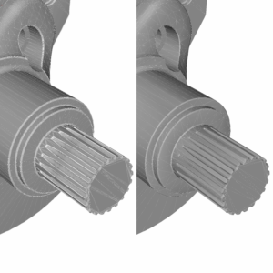
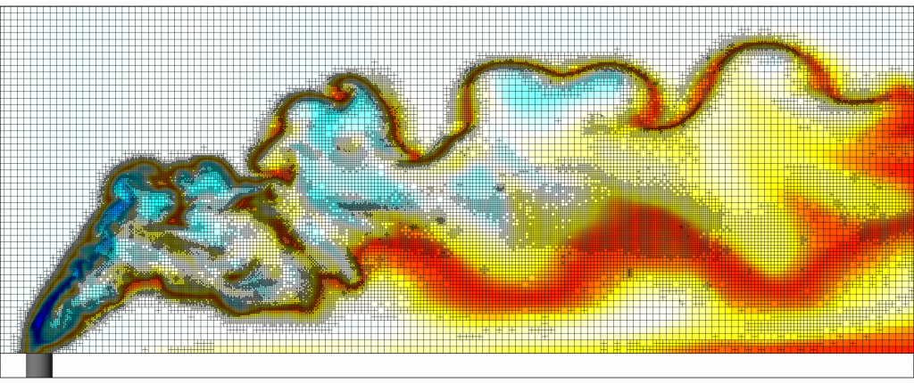
Automation is a hot topic these days. With the recent popularity of such books as <i>The 4-Hour Workweek</i> and <i>The 80/20 Principle</i>, the idea of achieving more with less is something we all dream about. The key to this of course is to work smarter, not harder. In CFD, the hard work often revolves around constructing and fine tuning the computational mesh. So how do we work smarter? In this business, working smarter means saving time <i>and</i> achieving a better result. This is accomplished by not only automatically creating a mesh of high-quality cells but also having the mesh dynamically respond to the flow field. I’ll describe in a minute how this is done, but first a little background.</p>
<p>For those of you not familiar with the origin of this blog’s title, “Automatic for the People” is the name of the eighth album from the rock band R.E.M. A fitting title for a post about automated meshing, but even though I consider myself somewhat of a music aficionado, I had no clue where this name came from. After doing a little googling I learned that it was inspired by the slogan of <i>Weaver D’s Delicious Fine Food</i>, a restaurant located in the band’s hometown of Athens, Georgia. According to <a href="http://stason.org/TULARC/music-bands/r.e.m./12-Where-does-the-title-Automatic-for-the-People-come-fr.html#.Ui9EAXmd4cE" target="_blank" rel="noopener noreferrer">this reference</a>, the slogan means that restaurant patrons <i>automatically</i> get what they want. As in “Do I get fries with that?” “<i>Automatic!</i>” “Can I get my check?” “<i>Automatic!</i>” If only Weaver D specialized in CFD…</p>
<p>My first experience making a complicated mesh was in graduate school. I remember spending hours, days, even weeks structuring cells such that the overall mesh conformed to the strict rules of the CFD solver. When I finally finished I felt an enormous sense of accomplishment, but also a huge sense of relief. However with this relief came big uncertainty. Did I have resolution in the correct places? I didn’t know. Was I anywhere near the point of grid convergence? Your guess was as good as mine. For better or for worse, I was done with the mesh and was going to run the heck out of it, no questions asked.</p>
<p>There is a school of thought that believes that making a mesh by hand is essential to achieving an accurate solution. Think about that for a moment. If you know where all of the mesh resolution should go ahead of time then you must already know what the flow solution looks like. But if you already know what the flow solution looks like, why do you need to run the simulation? The truth is that guessing where the mesh resolution should go ahead of time is quite challenging, even impossible for most cases. My graduate school meshes took a long time to generate and had no guarantee that they would correctly resolve the flow for the cases that I threw at them. Unfortunately, similar meshes still show up today, particularly in the combustion community.</p>
<p>So what’s the secret sauce to creating an optimum mesh? (Hint: it’s not the hot sauce at <i>Weaver D’s</i>!) In a 2004 Stanford workshop, Professor Wagdi Habashi of McGill University stated that in order to achieve mesh independence, we “cannot let the user decide where to generate and concentrate points.” He also indicated that “a mesh that is good for a flow condition can be shown not to be as good for a different condition, for the same geometry” (for more details on his presentation, google the phrase “meshing by guessing”).</p>
<p>So the secret sauce is in fact the fluid flow itself. Only when the flow solution is brought into the mesh generation process will the guess work be removed and an optimal mesh achieved. This is accomplished by automatically creating the mesh every time-step by adapting to the flow field. It’s the CFD-equivalent to <i>Weaver D’s</i>. “Is my mesh adequately resolved?” “<i>Automatic!</i>” “Is it sufficient for other flow conditions?” “<i>Automatic!</i>” Automated meshing isn’t going to guarantee you a 4-hour workweek, but it will give you more time and more confidence to stand behind your simulations.</p>
<p class="italic">In case you missed the other posts in the series, here they are:</p>
<ul class="italic">
<li>Part One: <a href="https://convergecfd.com/blog/toward-predictive-combustion-a-blog-series">Toward Predictive Combustion</a> a&nbsp;blog series</li>
<li>Part Three: <a href="https://convergecfd.com/blog/now-available-in-hd-from-the-toward-predictive-combustion-blog-series/">Now Available In HD</a></li>
<li>Part Four: <a href="https://convergecfd.com/blog/a-call-to-order">A Call To Order</a></li>
</ul>
]]>
            </summary>
                                    <updated>2013-09-30T06:22:09+00:00</updated>
        </entry>
            <entry>
            <title><![CDATA[Toward Predictive Combustion: A Blog Series]]></title>
            <link rel="alternate" href="https://convergecfd.com/blog/toward-predictive-combustion-a-blog-series" />
            <id>https://convergecfd.com/90</id>
            <author>
                <name><![CDATA[Kelly Senecal]]></name>
            </author>
            <summary type="html">
                <![CDATA[<p><img decoding="async" loading="lazy" class="alignright size-full wp-image-918" src="https://cdn.convergecfd.com/ic_flame31-300x205-1.png" alt="ic_flame31-300x205" width="300" height="205" />When I first started running CFD back in the 90’s, coarse grids and simplified combustion models were the norm, and for good reason – processor speeds were slow and simulations were mainly run in serial. Fast forward to 2013 and now we have a different story. Most commercial codes run in parallel and CPU speeds have increased significantly. It’s now easier than ever to incorporate more resolution and more chemistry in your simulations. But there are other pieces that are needed to solve the predictive combustion puzzle. When properly linked, these pieces can work together to provide an accurate solution to one of the most complex problems in CFD today.</p>
<p><strong>Automatic for the people</strong></p>
<p>Automatic, adaptive mesh generation – for predictive combustion simulations, it’s not just convenient, it’s necessary. If you’re a CFD user, I’m guessing that the idea of never needing to make a mesh again is a dream come true. With this roadblock removed, you can spend more time performing and analyzing your simulations. But perhaps even more importantly, the guess work is removed from the mesh generation process. How can users be asked to generate a mesh ahead of time when the optimal mesh differs from case to case?</p>
<p><strong>Now available in HD</strong></p>
<p>High resolution is the key to predictive combustion simulations. As much as we would like CFD to be grid independent, it’s not. In fact, if coarse and fine grids give you the same answer then chances are your solution is not predictive. Why? Because complicated flows need mesh resolution in order to be accurate. What is important is that you understand the sensitivity of the solution to the resolution and that the simulations are grid-convergent.</p>
<p><strong>A Call to Order</strong></p>
<p>Low order numerical schemes typically suffer from over-mixing. Why is this bad? Because over-mixing reduces accuracy by smearing the flow field. With this loss of accuracy comes a false sense of repeatability for systems that are inherently non-linear. Running with higher order schemes helps alleviate these problems.</p>
<p><strong>Divide and conquer</strong></p>
<p>In this day and age, multi-core CFD should be a given. When was the last time you ran a simulation in serial? Nevertheless, this piece should not be overlooked. Running with high resolution would not be possible without the ability to divide a simulation on a number of processors. Massively parallel computations introduce their own set of challenges and are the focus of current research and development in the combustion community.</p>
<p><strong>Next top model</strong></p>
<p>While the items above allow us to say adios to large cells, we’re still not anywhere close to running DNS for practical combustion systems. Accurate, grid-convergent models are still needed for many of the physical processes included in CFD simulations.</p>
<p><strong>Pushing back the boundaries</strong></p>
<p>Engineers typically need their results yesterday. Even with faster processors and parallel computing, it’s tempting to run with the smallest domain and shortest time possible. However, along with increased accuracy comes the need to expand computational boundaries in both space and time.</p>
<p><strong>Good chemistry</strong></p>
<p>You may be wondering why this one is listed last as this is, after all, a post about predictive combustion modeling. Having the ability to solve reaction chemistry in a fast and accurate way is critical for calculating performance and emissions. However listing this last emphasizes a very important point – you can have the most accurate reaction mechanism with the fastest solver but if the flow and mixing are not adequately predicted it doesn’t matter.</p>
<p>This concludes the first installment in this blog series on predictive combustion modeling. Stay tuned in the coming weeks for posts dedicated to each of the above topics.</p>
<p class="italic">In case you missed the other posts in the series, here they are:</p>
<ul class="italic">
<li>Part Two: <a href="https://convergecfd.com/blog/automatic-meshing-for-the-people-from-the-toward-predictive-combustion-blog-series">Automatic Meshing For The People</a></li>
<li>Part Three: <a href="https://convergecfd.com/blog/now-available-in-hd-from-the-toward-predictive-combustion-blog-series/">Now Available In HD</a></li>
<li>Part Four: <a href="https://convergecfd.com/blog/a-call-to-order">A Call To Order</a></li>
</ul>
]]>
            </summary>
                                    <updated>2013-08-26T06:29:16+00:00</updated>
        </entry>
            <entry>
            <title><![CDATA[It’s All About The Mesh – Cartesian Cut-Cell Approach]]></title>
            <link rel="alternate" href="https://convergecfd.com/blog/its-all-about-the-mesh-cartesian-cut-cell-approach" />
            <id>https://convergecfd.com/89</id>
            <author>
                <name><![CDATA[Convergent Science]]></name>
            </author>
            <summary type="html">
                <![CDATA[
<div id="attachment_4079" style="width: 160px" class=" wp-caption  alignright">
<img loading="lazy" decoding="async" class="size-thumbnail" src="https://cdn.convergecfd.com/RobKaczmarekheadshot.png" width="150" height="150">
<p>
 <span class="bold">Author: <br> Rob Kaczmarek</span>
 <br> <span style="text-transform: none;">Director of Global Marketing</span>
</p>
</div>


<figure class="wp-block-image alignright"><img decoding="async" src="https://cdn.convergecfd.com/RJK-Aug-19-300x247-1.png" alt="RJK-Aug-19-300x247" class="wp-image-921"/></figure>


<p>The CFD mesh is one of the most discussed topics within the engineering community. It can be both problematic and time consuming – not to mention a source of numerous inaccuracies. There are different approaches to meshing but in this blog we are going to take a look at the cut-cell Cartesian approach and some of its benefits.</p>


<h3 class="wp-block-heading">Body-fitted</h3>


<p>One of the most obvious benefits of the cut-cell Cartesian approach is the fact that you have a body-fitted mesh. This ultimately means that your mesh fits perfectly with your geometry, reducing the number of inaccuracies that propagate through the rest of the domain. Because of this, the cut-cell Cartesian approach makes handling complex and moving geometries much easier and accurate by cutting the cells rather than stretching and compressing the cells to fit.</p>


<h3 class="wp-block-heading">Independent resolution</h3>


<p>Because this method cuts the volume cells at the wall, the mesh resolution is then independent of the geometry resolution. In other words, you can have a high fidelity geometric representation and a very coarse mesh. This can help speed up run-time calculations for one-off “let’s see what happens” designs ultimately aiding in rapid virtual prototyping.</p>


<h3 class="wp-block-heading">Lack of skewness</h3>


<p>Skewness is an inherent issue whenever you have a moving boundary using traditional meshing methods. This is not the case for the cut-cell Cartesian method. The mesh remains stationary and as the geometry moves the cells are cut and no compressing or stretching of the volume mesh occurs. This lack of skewness increases accuracy of the results and makes it the preferred method when dealing with moving geometries.</p>


<h3 class="wp-block-heading">Near-wall flow</h3>


<p>The other benefit of the cut-cell Cartesian method is added cell refinement at the wall, as this will have a positive impact on accuracy. With other methods, the full grid needs to be provided as an input and the actual surface geometry is no longer available. As a result, the accuracy of the surface location is limited by the resolution in the original grid. Any grid refinement performed during the simulation will cut the existing cells, and any resolution added near walls will not result in a better representation of the actual geometry. On the other hand, using the cut-cell Cartesian method requires the original surface information to be maintained. Thus, grid refinements will improve accuracy in the near-wall flow predictions.</p>
]]>
            </summary>
                                    <updated>2013-08-19T06:33:29+00:00</updated>
        </entry>
            <entry>
            <title><![CDATA[CFD with no meshing… where’s the catch?]]></title>
            <link rel="alternate" href="https://convergecfd.com/blog/cfd-with-no-meshing-wheres-the-catch" />
            <id>https://convergecfd.com/88</id>
            <author>
                <name><![CDATA[Convergent Science]]></name>
            </author>
            <summary type="html">
                <![CDATA[
<div id="attachment_4079" style="width: 160px" class=" wp-caption  alignright">
<img loading="lazy" decoding="async" class="size-thumbnail" src="https://cdn.convergecfd.com/RobKaczmarekheadshot.png" width="150" height="150">
<p>
 <span class="bold">Author: <br> Rob Kaczmarek</span>
 <br> <span style="text-transform: none;">Director of Global Marketing</span>
</p>
</div>


<figure class="wp-block-image alignright"><img decoding="async" src="https://cdn.convergecfd.com/commodore-300x185-1.png" alt="commodore-300x185" class="wp-image-930"/></figure>


<p>Every CFD engineer in the world today has experienced the pain of meshing.&nbsp; The endless hours of trying to get a mesh to work with a particular complex geometry, trying to decide between structured and unstructured, deciding where to put mesh resolution, etc.&nbsp; With recent advancements meshing may be as outdated as your old Commodore 64.</p>


<p>Not the mesh itself, but the process of creating a user defined mesh.</p>


<p>With recent advancements in commercial CFD codes the ability to automate the meshing process is becoming more and more prevalent. We’ve assembled the Top 5 features to look for when evaluating a product that claims to have automated meshing.</p>


<h4 class="wp-block-heading">5 Important Features of Automated Meshing</h4>


<p><strong>1. Method Used</strong>. When looking for a CFD tool with automated meshing it’s important to look for the tool that automates at run-time, for each time step, with a stationary, orthogonal, structured mesh. This will reduce inaccuracies from numerical diffusion due to a deforming mesh for moving boundary applications. The Cartesian cut-cell approach overcomes many of the limitations of the immersed boundary method and is therefore preferred.</p>


<p><strong>2.</strong>&nbsp;<strong>Complex Moving Geometries</strong>.&nbsp;The ability to handle complex geometries is a must and the automated mesher must be robust enough to handle any geometry, moving or non-moving.</p>


<p><strong>3. Mesh Refinement</strong>.&nbsp;The ability to refine the mesh on the fly, at run-time, based on gradients is key. This will produce the best results with the least amount of computational expense by placing mesh elements when and where they are most needed. Fixed embedding is also a nice feature to have when you know exactly where the added mesh will be needed.</p>


<p><strong>4.</strong>&nbsp;<strong>Exact Geometric Representation</strong>. Having the true representation of your model will offer you the advantage of an exact geometric representation independent of the mesh size. This offers numerous benefits including the ability to apply more cells near a wall and get an increase in accuracy, and running a fast coarse mesh without distorting the geometric representation.</p>


<p><strong>5. Running in parallel</strong>. Meshing in parallel is essential to getting a timely CFD analysis. Without the mesh being created in parallel you run the risk of adding hours to your run times.</p>
]]>
            </summary>
                                    <updated>2013-07-11T09:30:51+00:00</updated>
        </entry>
    </feed>
