Benefits
Events
Products & Programs

Author:
Eileen Wagner
Research Engineer
Interest in home improvement has soared since the start of the pandemic, along with demand for the requisite tools. Saws, drills, sanders, and routers—what kind of motor do they use? Ideally, one that is powerful, easy to control, lightweight, affordable, robust, and low maintenance. In practice, no single motor meets all of these requirements.

Brushed DC motors are commonly used in tools because they are cheap and the speed and torque can be easily adjusted. However, they require frequent maintenance due to brush wear. Brushless motors are another option, and they provide high efficiency and power density. A drawback of brushless motors is that they rely on rare-earth permanent magnets, which are costly, not suitable for high speed rotation, and susceptible to damage at high temperatures. These limitations have spurred a renewed interest in alternative designs, including switched reluctance machines.
Though switched reluctance motors (SRMs) date back to the mid-nineteenth century, they never gained widespread use. A major reason for that was the lack of precise controllers. Now, with the availability of improved electronics, SRMs are getting a second look. SRMs are unique in that the windings are placed on the stator instead of the rotor. This enables a simplified, rugged design and low-cost manufacturing. In addition, they lack permanent magnets, which helps to further reduce costs. To operate, the current in the stator windings is switched from pole to pole, generating a rotating magnetic field. The rotor poles seek to align with the moving magnetic field and follow the path of least reluctance to drive motor spinning. One potential problem with SRMs is low torque density, which can be overcome by increasing the current and, inadvertently, heat. Because heat can degrade the windings and insulation and, over time, reduce performance and efficiency, accurate simulations are crucial for guiding the development of improved designs.
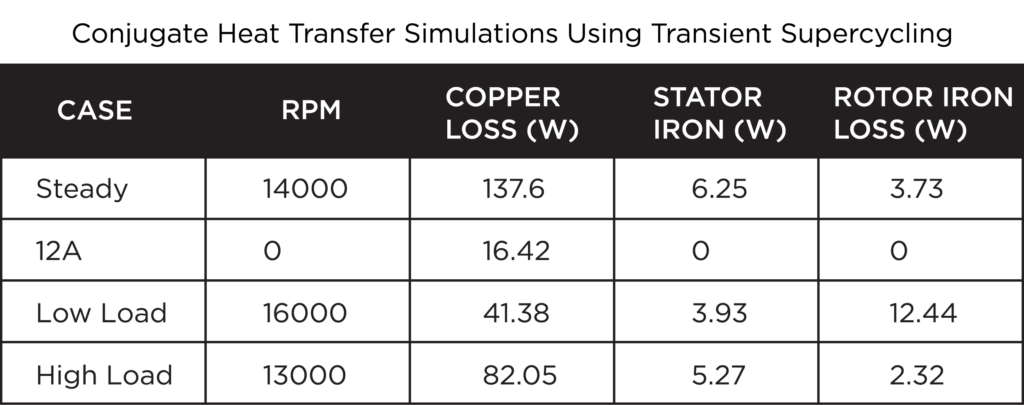
What improvements can be made to the conventional SRM to efficiently power a hand-held tool? In this blog post, we present the results of a collaborative effort between JMAG, the Shibaura Institute of Technology, and Convergent Science to evaluate a self-cooling SRM. This motor has a non-axisymmetric salient pole rotor with five poles and a segmented stator with six slots. The spinning rotor generates wind to cool the stator and windings. No fan is required due to the self-cooling effect, enabling an increase in motor volume and torque while retaining a small size. The motor was designed and characterized at Shibaura.1 JMAG was used to calculate electromagnetic (copper and iron) losses, which were applied as heat sources in CONVERGE to predict the temperature rise in the solid components and model the self-cooling effect of rotor spinning.
CONVERGE is well-suited to electric motor cooling simulations. CONVERGE’s coupling with JMAG enables seamless import of the NASTRAN geometry file that includes the computed electromagnetic losses. Conjugate heat transfer modeling is highly efficient with transient super-cycling time control and completes in a fraction of the time required for a fully transient calculation. And finally, CONVERGE offers superior grid control capabilities with autonomous meshing and Adaptive Mesh Refinement. These features allow high-speed motion of the rotor and dynamic air flow patterns to be captured with ease.
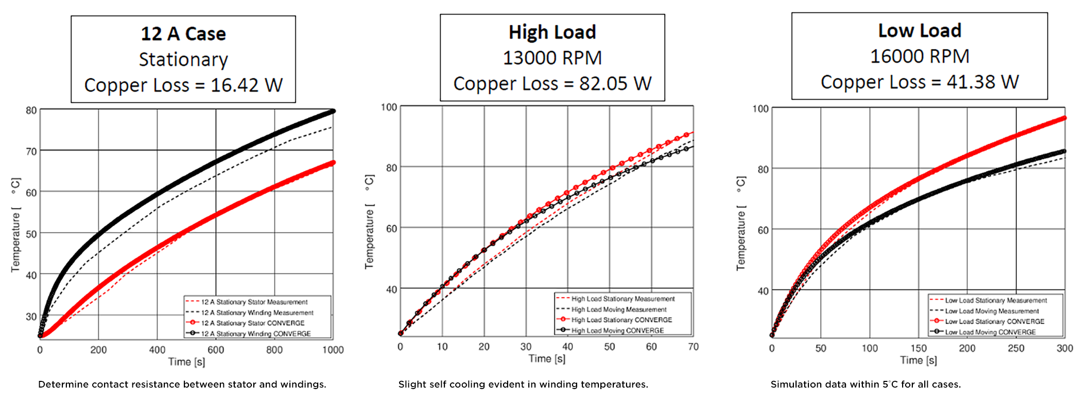
The copper loss in the windings and the iron losses in the stator and rotor (calculated in JMAG) were modeled as volumetric heat sources in CONVERGE. A separate case where a 12A current was applied to the windings in the absence of rotor spinning was simulated to determine the contact resistance between the windings and the stator (Figure 1).
Next, the self-cooling effect simulated in CONVERGE was compared to experimental results. In the high load case, self-cooling is minimal, while under low load, the effect is more pronounced. In all cases, the CONVERGE simulations match the experimental measurements within 5°C (Figure 2).
What about air flow? In this animation, the air flow path in the wake region is depicted with velocity vectors (Figure 3). Air enters from the radial direction and flows through the stator slots to cool the stator and windings. Conjugate heat transfer modeling with transient super-cycling depicts the increasing temperature of the solid stator during sustained motor operation.
The market for electric motors is expanding rapidly. Meeting this demand will require ongoing innovation—both a massive challenge and opportunity. With the combined capabilities of CONVERGE and JMAG, you’ll be equipped with powerful and efficient tools to drive the transition to a more electrified future.
Ready to simulate electric motor cooling? Contact us today!
References
1. Koinuma, K., Aiso, K., and Akatsu, K., “A Novel Self Cooling SRM for Electric Hand Tools,” 2018 IEEE Energy Conversion Congress and Exposition (ECCE), Portland, OR, United States, Sep 23–27, 2018. DOI: 10.1109/ECCE.2018.8557901


