
Valves
Valves regulate fluid flow through many systems, from internal combustion engines to the human heart. If you wanted to list every type of valve, you might start with ball valves, ring valves, reed valves, plate valves, poppet valves, gate valves, butterfly valves, check valves, heart valves and still have a long way to go. Perhaps it’s simpler to remember one thing they all have in common, which is that it is straightforward to simulate valves with CONVERGE.
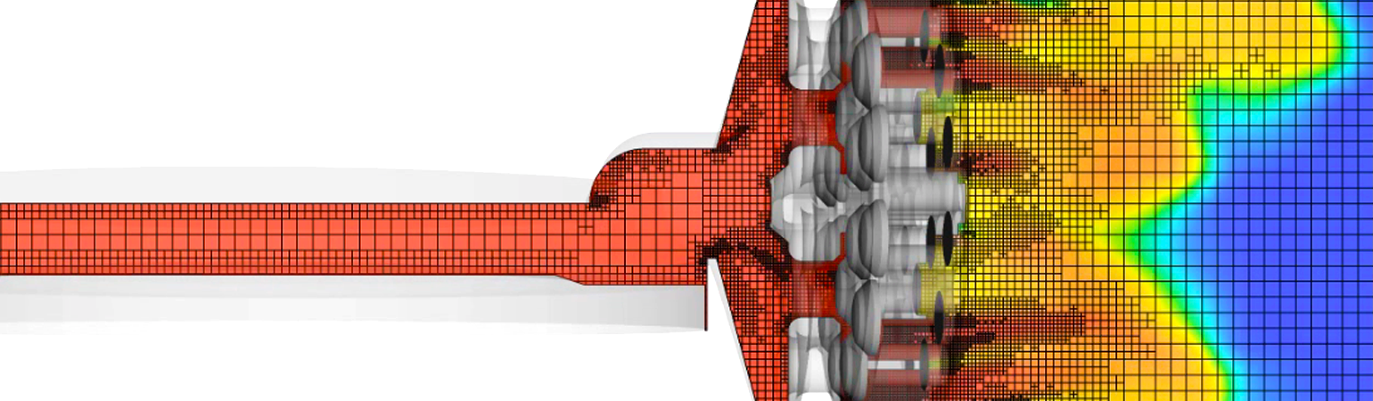
Simulating Complex Geometries
CONVERGE offers autonomous meshing capabilities that are purpose-built for complex moving geometries. Whether your valve is a heavy spring-loaded disc or a flexible reed, CONVERGE automatically generates a Cartesian mesh at runtime that is cut exactly at the valve boundary and produces a numerically stable solution. When the valve is in motion, CONVERGE regenerates the near-boundary mesh at each time-step, thus accounting for the moving boundary without morphing or distorting the mesh.
Because the CONVERGE approach is geometry-agnostic and fully automated, you can easily explore the effects of design changes without having to fiddle with templates or make a new mesh for each design. It’s also easy to execute simulations for different valve configurations—for example, changing the position of a throttle valve requires only minor changes to the surface geometry file that you provide as an input for CONVERGE.
Resolving Valve Flow
Another option suitable for some applications is to use a boundary-layer mesh around the valve surface. A boundary-layer mesh is a user-defined mesh that is created by extruding the triangulated surface in a direction normal to the valve boundary. CONVERGE uses the boundary-layer mesh near the valve and uses the autogenerated cut-cell Cartesian mesh in the rest of the domain. When the flow has a much stronger gradient in the direction normal to the surface than in other directions, a boundary-layer mesh can provide accurate results with fewer cells than a cut-cell Cartesian mesh.
Efficient Load Balancing at Varied Length Scales
CONVERGE’s autonomous meshing features are especially useful for modeling valve gaps with length scales much smaller than the overall length scale of the domain. For example, the clearance gap for a poppet valve in the injector of a natural gas direct-injection engine can be many orders of magnitude smaller than the engine bore. Similarly, in simulations of internal injector flows, the gap around the valve (or “needle,” in injector parlance) when it is opening or closing can be much smaller than the diameter of the chamber into which fuel is injected. Starting in CONVERGE 3.0, you can use the available meshing strategies to resolve these tiny gaps without any load-balancing tradeoff. This is because CONVERGE employs cell-based load balancing, in which cells are evenly distributed among processing cores. As a result, CONVERGE exhibits excellent parallel scaling for simulations with a wide range of cell sizes down to O(1000) cells per core.
Generating Flowbench Data
Flowbench experiments, often used by engine designers to study the airflow through intake ports, are perhaps the simplest way to analyze the fluid dynamics around a valve. Flowbench measurements include steady-state values for the bulk flow and other flow parameters, obtained for different intake valve lifts and (if applicable) swirl plate positions. With CONVERGE’s steady-state solver, you can run efficient simulations to calculate common flowbench quantities such as mass flow rate, flow coefficients, and swirl. Adjusting the intake valve lift or rotating the swirl plate is as simple as editing a single input file. To ensure accurate results, you can use AMR to resolve complex flow features throughout the domain, combined with a boundary-layer mesh at the valve surface.
Prescribing Valve Motion
For some applications, such as internal combustion engines, external components of the machinery drive the valve motion. To simulate this motion in CONVERGE, the user specifies when the valve opens and closes and provides a valve lift profile to determine the valve position at each time-step. CONVERGE always maintains a finite gap between the port and the valve, using a virtual boundary to cut off the flow when the valve is closed. This approach does not fill the gap with tiny cells, unlike other approaches that tend to add more resolution than needed by shrinking the mesh as the valve closes.
Understanding Cavitation
Cavitation occurs when pockets of vapor form within a liquid because of a sudden drop in pressure. These pockets collapse when the pressure rises, releasing energy in the form of a compression wave. In devices with liquid flows, such as pumps and fuel injectors, cavitation can occur in localized low-pressure zones that form as the liquid flows around valves within the device. Understanding how cavitation is induced or suppressed can be important for minimizing damage to the valves and other nearby parts. In fuel injection applications, it can also be important for optimizing fuel-air mixing. CONVERGE offers robust multi-phase modeling capabilities, including a built-in cavitation model, so you can identify conditions in which cavitation is likely to occur and adjust your design accordingly.
Modeling Flow-Driven Valves
For valves that open and close in response to fluid forces, it’s not enough to model the fluid alone—you also must account for the interactions between the fluid and the valve. An accurate fluid-structure interaction (FSI) model can help predict quantities that are crucial for overall performance, such as valve lift, mass flow rates, and internal chamber pressures. It can also help predict the stress on the valve so you can optimize your design to avoid excessive wear.
CONVERGE offers a number of FSI models with varying levels of complexity:
- The rigid-body FSI model is suitable for valves that do not change shape in response to the fluid force, such as ball valves, ring valves, and plate valves.
- The beam deflection model, which captures the deformation and motion of an object that can be approximated as one-dimensional, is a good choice for reed valves.
- The general FSI model requires a fully coupled co-simulation with the Abaqus or GT-SUITE finite element analysis (FEA) solver. This approach treats the valve as a deformable three-dimensional object.
Figures 1-2 show examples of CONVERGE FSI modeling applied to valves in a refrigeration compressor and in a natural gas engine.

Figure 1: Valve lift for reed valves in a reciprocating compressor predicted from CONVERGE beam deflection model (light blue lines with cross symbols), compared to experimental data (black lines). Plots show suction (top) and discharge (bottom) valve lift at two operating conditions.1

Figure 2: Stuffing box pressure in a large-bore, two-stroke, natural gas engine. Green and black lines show the pressure predicted by CONVERGE using an FSI model for the reed valves with two different boundary conditions. Red line shows experimental results.2
Accounting for Oil Stiction
In devices such as oil-flooded compressors, the oil film on the surface of a valve exerts an adhesive stiction force, which might be a non-negligible correction to the force calculated from an FSI model. The most rigorous way to account for stiction is to combine the FSI model with CONVERGE’s volume of fluid (VOF) model, which solves for the mass fraction of oil throughout the domain. If this approach is too costly for your application, CONVERGE can also incorporate an empirical model of the stiction force.
References
[1] Rowinski, D., Sadique, J., Oliveira, S., and Real, M., “Modeling a Reciprocating Compressor Using a Two-Way Coupled Fluid and Solid Solver with Automatic Grid Generation and Adaptive Mesh Refinement,” 24th International Compressor Engineering Conference, Purdue University, West Lafayette, IN, United States, July 9-12, 2018.
[2] Mashayekh, A., Jacobs, T.J., Patterson, M., and Etcheverry, J., “Prediction of Air-Fuel Ratio Control of a Large Bore Natural Gas Engine Using Computational Fluid Dynamic Modeling of Reed Valve Dynamics,” International Journal of Engine Research, 2017. DOI: 10.1177/1468087416686224


