Benefits
Events
Products & Programs


Author:
Lydia Manger
Research Engineer
In my first year of graduate school, a friend always filled up her water bottle, dropped some ice cubes into it, and then shook it up in order to cool the water faster. If she had added the ice cubes and let the water bottle sit, eventually all the water would equilibrate to the same temperature, but that would take a while without any movement—the water next to the ice cubes would cool down quickly, but the water farther away would cool down at a much slower rate. By shaking it up, she agitated the water and ice so that the ice came into contact with more of the warm water that needed to be cooled. This “cocktail shaker effect,” I would later find out, also applies to cooling engines.
Combustion in an internal combustion (IC) engine occurs on top of the piston, which means that there is an extraordinary amount of heat generated on the piston crown. If left unmediated, this heat can cause the piston to break. The threat of piston damage is particularly high in diesel engines because more heat is generated in the cylinder than in a traditional gasoline engine. Unlike a bottle of warm water, though, we can’t just drop a few ice cubes into the cylinder to act as a heat sink.
Here we see how engineers can use CONVERGE to efficiently solve the problem of cooling the piston so that it isn’t damaged by heat. The idea is simple—use engine oil as a heat sink—but the implementation is complex since the piston is constantly moving and nothing can be in contact with the piston crown inside the cylinder.
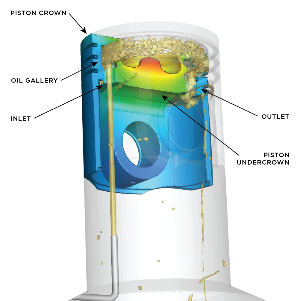
Since the heat sink can’t be inside the cylinder on the piston crown, there is an oil gallery in contact with the undercrown of the piston, as shown in Figure 1. Engine oil is taken through a pump, pressurized, and constantly sprayed at the oil gallery inlet hole. In the video below, you will see how the oil enters the gallery, and, as the piston motion continues, the oil sloshes inside the oil gallery, absorbing heat from the piston before exiting the outlet hole on the other side of the gallery.
There are several factors that are important to consider when designing this type of cooling system, all of which CONVERGE is well-equipped to handle. What size and shape should the inlet and outlet holes be to capture the stream of oil? How much oil will enter the gallery compared to how much was sprayed (i.e., capture ratio)? What is the best design of the gallery so that the oil effectively absorbs heat from the piston? What ratio of the gallery volume should be occupied (i.e., fill ratio) to ensure that the oil can move and absorb heat efficiently? CONVERGE provides answers to these questions and others through a volume of fluid (VOF) simulation.
Because a simple boundary condition is not predictive of the heat transfer throughout the entire piston, we use conjugate heat transfer (CHT) to more accurately predict the piston cooling by solving the heat distribution inside the piston. Understanding how heat transfer affects the whole piston is an essential step toward designing a geometry that will effectively cool more than just the piston surface. While CHT can be computationally expensive due to the difference in time-scales of heat transfer in the solid and fluid regions, CONVERGE provides the option to use super-cycling, which can significantly reduce the computational cost of this type of simulation.
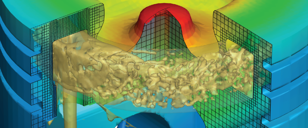
In the video below, you will see how the above factors have been optimized to dissipate heat from the piston crown and throughout the piston as a whole. In the video on the left, you can watch the temperature contours change during the simulation as heat dissipates. The second view shows how CONVERGE’s Adaptive Mesh Refinement (AMR) is in action throughout the simulation, providing increased grid resolution near the inlet and around the oil gallery, where it is needed most.
Ready to run your own simulations to optimize oil jet piston cooling? Contact us today!


