Benefits
Events
Products & Programs


Author:
Clayton Grow
Senior Research Engineer
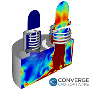
As we explore new applications for CONVERGE, we look for products in which the flow and motion might be problematic for other CFD programs to capture. In the past year, we found an application that shared many characteristics with our flagship application, internal combustion engines: the reciprocating compressor. The two applications share a few key components: a cylinder, a piston reciprocating inside it, intake valves, and exhaust valves. In fact, a reciprocating compressor is sort of like an engine in reverse; instead of the volume of the cylinder expanding due to combustion driving the piston, the piston is controlled by outside forces, and the piston then compresses the gas inside the chamber. While these two mechanisms have many features in common, there are some major differences. The obvious difference: no combustion in a compressor. But there is a compressor phenomenon that is equally challenging to simulate: fluid-structure interaction of the pressure relief valves that control flow into and out of the compression chamber.
Many of the pressure relief valve and compressor manufacturers have limited their CFD studies to steady-state flow. The main reason for this: making the mesh to accommodate the motion of objects with unprescribed motion can be quite difficult.
This is not to say that steady-state pressure relief valve simulations are without value; they can indeed provide useful insight early in the design cycle. But in order to understand some of the more complex flow phenomena near a pressure relief valve, designers need a more detailed analysis of how the flow evolves over time.
One of the most critical phases of the compression cycle is the moment at which the gas begins to flow through an inflow or exhaust valve. When designers use traditional meshing methods and automated meshing scripts, they often need to guess the proper grid resolution and cell orientation in this small valve gap. Such an estimation can be problematic because as the gap grows, these cells need to either stretch or move to accommodate the valve motion. These stretching and moving cells can cause errors in the transport of calculated conditions (velocity, turbulence, species, etc.). These errors can propagate and cause major discrepancies in the results.
With CONVERGE, simply choose a base grid size and a level of refinement that will ensure the minimum number of layers of cells will fit in the smallest gap. The mesh never moves in CONVERGE; the solver regenerates the mesh each time-step to accommodate the motion of any part, prescribed or flow-driven. CONVERGE automatically generates the mesh in the small gap through a pressure relief valve, with no cell orientation transport errors — the mesh is always perfectly orthogonal. This makes the simulation setup for this critical area much simpler, easier, and the results more accurate.
Another important concept to study in a reciprocating compressor or a pressure relief valve is the frequency of the check valve motion and the frequency of the pressure waves caused by the motion of the valves and the piston. Pressure waves are inherently transient, so simulating them with a steady-state solver is problematic and requires many significant assumptions. Without the burden of creating and fine-tuning a mesh for every time-step, CONVERGE offers the ability to capture the shape and frequency of these pressure waves with Adaptive Mesh Refinement. In areas where there is a steep gradient in the velocity of a gas — often near the valve upon opening, CONVERGE automatically adds refinement to capture the precise shape of the pressure wave. You can control the refinement by choosing values for a few simple parameters in the Adaptive Mesh Refinement dialog box.
“Tilt” is the dreaded nemesis of any pinball wizard. The tilt of a plate in a valve can also affect the pressure in different areas of a compressor in unexpected ways. CONVERGE offers a 6- degree-of-freedom (6DOF) fluid-structure interaction model that can accurately simulate the tilt of a plate valve pushed open against the dynamic resistance of a spring.
In much the same way a Pinball Wizard needs to have a good idea of how hard a pinball bounces off of a flapper, valve and compressor designers need to have a good idea how the valve bounces off the valve seat. CONVERGE’s options for contact modeling can simulate the bounce of the valve against the valve seat. The fully coupled, fully automated meshing at runtime in CONVERGE captures this bouncing valve with utmost precision.
Whether designing a pressure relief valve or a reciprocating compressor, CONVERGE offers the tools needed to capture the complex flow structures and the fluid-structure interactions that are vital to the design of these products that are used in a wide variety of industrial and household applications.


